Wireless Engineering and Technology
Vol.3 No.2(2012), Article ID:18933,4 pages DOI:10.4236/wet.2012.32014
Wireless Power Feeding with Strongly Coupled Magnetic Resonance for a Flying Object
![]()
1Department of Advanced Energy, The University of Tokyo, Tokyo, Japan; 2Department of Aeronautics and Astronautics, The University of Tokyo, Tokyo, Japan.
Email: masayoshi.koizumi@gmail.com
Received October 21st, 2011; revised December 14th, 2011; accepted January 14th, 2012
Keywords: Wireless Power Transmission; Coupling Coefficient; Impedance Matching; Quality Factor; Resonator
ABSTRACT
Wireless power feeding was examined with strongly coupled magnetic resonance for an object moving in 3-D space. Electric power was transmitted from the ground to an electrically powered toy helicopter in the air. A lightweight receiver resonator was developed using copper foil. High Q of greater than 200 was obtained. One-side impedance matching the transmitter side was proposed to cope with high transmission efficiency and the receiver’s weight reduction. Results show that the efficiency drop near the ground was drastically improved. Moreover, the measured efficiency showed good agreement with theoretical predictions. A fully equipped helicopter of 6.56 g weight was lifted up with source power of about 5 W to an altitude of approximately 10 cm.
1. Introduction
Magnetic resonance power feeding, a unique wireless power transmission technology, is now in demand in various fields. In 2007 and 2008, an MIT group reported wireless power transmission theory based on optics and photonic crystal theories, explaining it as a phenomenon caused by near-field evanescent waves [1,2]. One feature of this technology is its high transmission efficiency at meter-order distance [3], which will enable feeding of power in applications such as electric cars, micro-robots, and battery-less sensors.
A formula for the transmission efficiency can be derived from electric circuit theory [4]. Efficiency is expressed as a function of a Figure-of-Merit (fom) fom = kQ under an impedance-matched condition. Here, k and Q respectively denote the induction coupling coefficient and coil quality factor. The formula is valid for magnetic resonance power transmission and for inductive power transmission.
A remarkable feature of wireless power transmission with strongly coupled magnetic resonance is its effectiveness at mid-ranges, which is several times greater than the resonator diameter. This feature enables wireless power feeding to a mobile object moving freely in a three-dimensional space. This report describes a powerfeeding demonstration to an electrically powered helicopter. The objective is development of an efficient, compact, and lightweight resonator, with validation of the impedance-matching theory through the demonstration.
2. Impedance Matching Theory
Impedance matching, adjustment of the impedance ratio, is conducted in antenna tuners using variable capacitor units and inductive transformers to maintain high transmission efficiency. In the helicopter application, the coupling coefficient k varies dynamically because of the helicopter’s altitude change; both very low Ohm loss and a wide range of impedance transformation are necessary for strongly coupled magnetic resonance.
Considering the power transmission from a resonator with quality factor QS, impedance Z0, and resonance frequency ω0 to another resonator with QD, Z0, and ω0 at the AC frequency of ω, then the transmission efficiency can be derived using Kirchhoff’s second law as shown below [4].
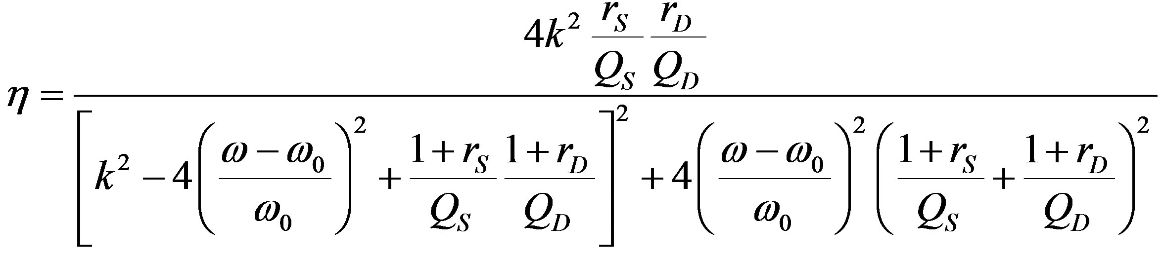 (1)
(1)
Therein, rS and rD respectively represent ratios of the source’s and device’s impedance Z0S and Z0D to the resonator resistance RS and RD, defined as

and
 (2)
(2)
In the ω-rS-rD domain, η reaches its maximum value under conditions of
 (3)
(3)
and
 . (4)
. (4)
Then, maximum efficiency is expressed as
 . (5)
. (5)
A typical resonant coupling system with input and output inductive transformers is presented in Figure 1. The excitation coil is inductively coupled to the transmitter resonator, and the pickup coil is connected to the receiver resonator. rS and rD are adjustable by changing their respective coupling coefficients kS and kD.
Figure 2 portrays an equivalent circuit of the system. The source impedance ratio is transformed to kSZ0S/RS. The device impedance ratio is transformed to kDZ0D/RD.
One-side impedance matching is one means to simplify the receiver device. The transmitter takes the optimum impedance ratio, although the receiver impedance ratio is not controlled. The theoretical efficiency of oneside control η1 is expressed as [5]
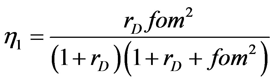 . (6)
. (6)
The theoretical transmission efficiencies indicated in Equations (1), (5), and (6) are depicted in Figure 3 for
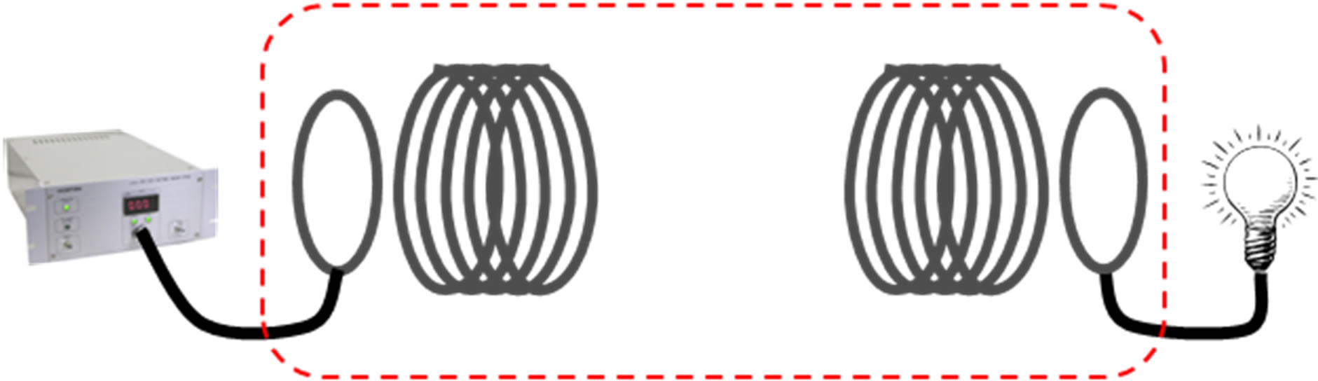
Figure 1. Power transmission system with input and output inductive transformers. From left, an excitation coil, a transmitter resonator, a receiver resonator, and a pickup coil.
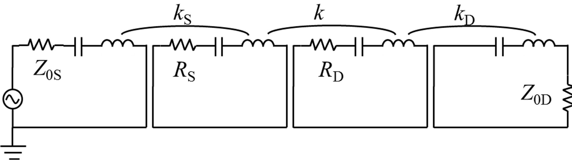
Figure 2. Equivalent circuit of the power transmission system with input and output inductive transformers.
QS = QD = 200. When the impedance ratio is matched, then the transmission efficiency is improved, especially at a short transmission distance.
3. Loop Resonator
A high Q, compact, and lightweight receiver resonator is necessary to make a helicopter fly without a battery. For this study, a resonator was fabricated consisting of a rectangular loop and a mica condenser. It was composed of a copper pipe with 4 mm outer diameter to reduce its weight. The loop side length and the mica condenser capacitance were selected for the resonator to have a resonance frequency exactly equal to 40.68 MHz, which is the power source AC frequency.
Table 1 presents specifications of the receiver resonator along with those of the transmitter resonator whose structure was the same as that of the receiver. As the table shows, the dielectric loss and ohmic loss in the mica capacitor was the predominant energy loss mechanism limiting Q for both resonators.
4. Effect of Impedance Matching
4.1. Electric-Powered Helicopter with a Receiver and a Rectifier
A receiver resonator, a pick-up coil and a rectification
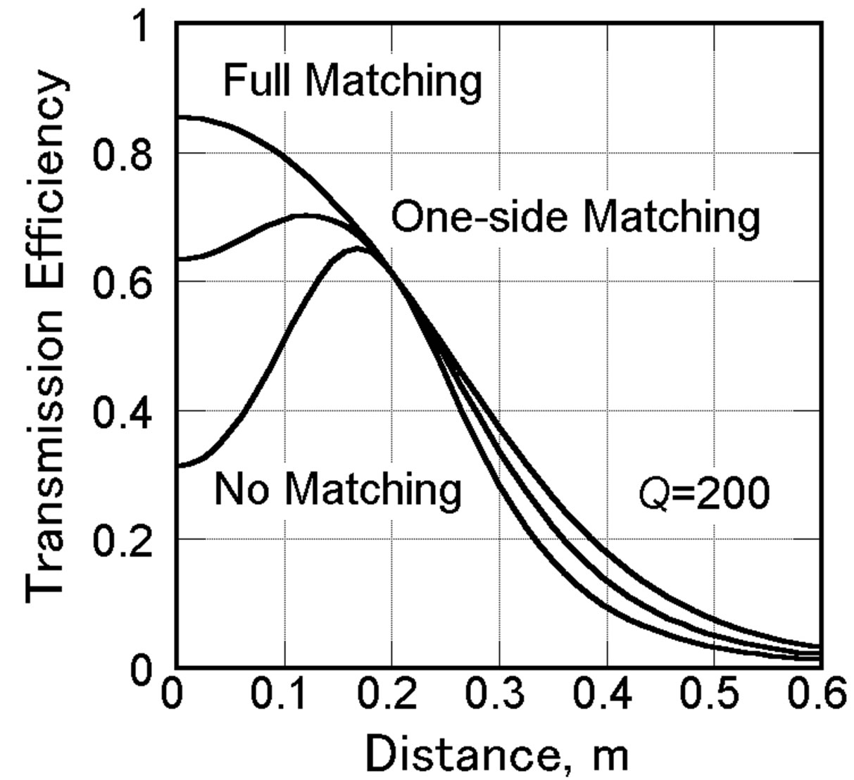
Figure 3. Theoretical transmission efficiency with and without impedance matching.

Table 1. Specifications of the resonators.
circuit are mounted on an electrically powered toy helicopter, as portrayed in Figure 4. No battery is used. The copper foil pickup coil limits weight and drag. The pickup coil is connected to the motor through a bridge circuit composed of four Schottky diodes (1N5818, ST micro; Fuji Electric Co. Ltd.), which operate at high frequency with low forward voltage drop (VF = 0.550 V).
This fully equipped helicopter weighed 6.56 g. The impedance ratio was optimized at 10 cm altitude.
4.2. One-Side Impedance Matching on the Transmitter Side
The impedance ratio on the transmitter side is mechaniccally adjustable by changing the relative position of the excitation coil with respect to the transmitter resonator as presented in Figure 5, where it was controlled by sliding the excitation coil.
Figure 6 shows the theoretical relation between the optimum impedance ratio and transmission distance as indicated in Equation (4), and the necessary distance between the centers of excitation coil and resonator for matching.
The measured transmission efficiency is depicted in Figure 7 along with the predictions. The distance has been normalized by the receiver resonator side length. The efficiency has a peak around normalized transmission distance = 1 because the impedance ratio has been optimized for that altitude. A flat efficiency characteristic
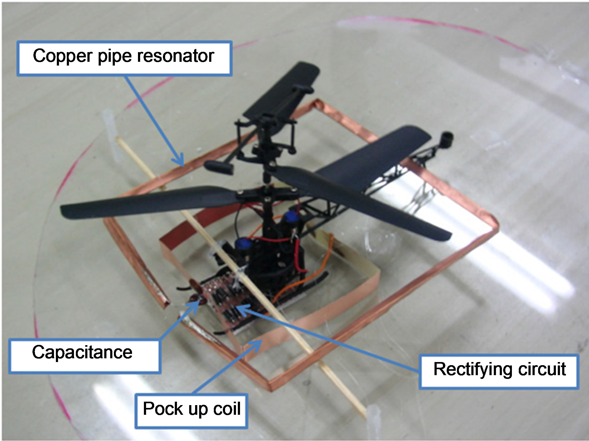
Figure 4. Electrically powered toy helicopter with a receiver resonator, a pickup coil, and a rectifying circuit.

Figure 5. Impedance control by sliding of the excitation coil.
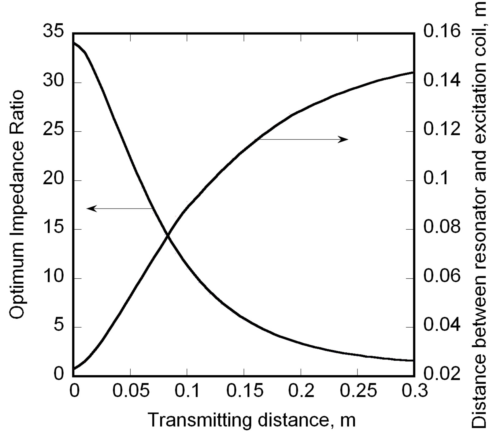
Figure 6. Optimum impedance ratio and optimum distance of the centers of excitation coil and resonator.
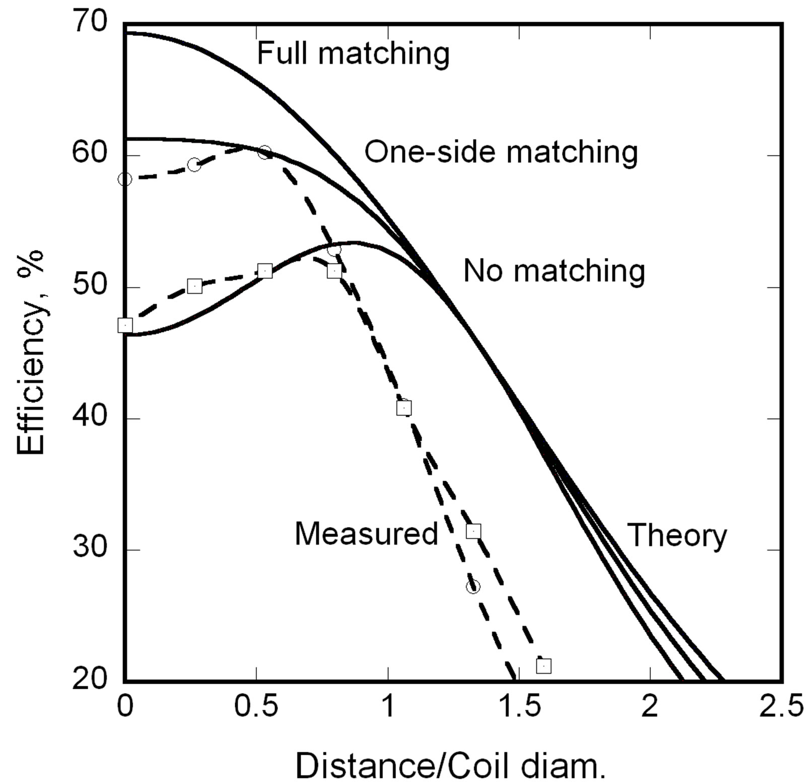
Figure 7. Transmission efficiency with impedance matching.
is obtained near the ground with one-side matching. The helicopter was lifted up at the source output power of about 5 W to altitude of approximately 10 cm.
4.3. Automatic Impedance Matching
One feature of magnetic resonance power feeding is the measurability of transmitted power on the transmitter side. Therefore, the impedance ratio on the transmitter side is adjustable using no information from the receiver side. Reflected power is measured using a directional coupler on the transmission, as portrayed in Figure 8. Then, an actuator moves the excitation coil in the horizontal direction to adjust its relative position with respect to the resonator until the reflected power is minimized.
5. Conclusions
The power transmission efficiency of the magnetic reso-

Figure 8. Schematic of automatic impedance matching system.
nance power feeding with impedance matching is deduced from the electric circuit theory. One-side impedance matching on the transmitter side is proposed to cope with high transmission efficiency and the receiver’s weight reduction. Results show that great efficiency improvement can be predicted, especially at a short transmission distance.
A lightweight receiver system was developed with high Q of greater than 200. In the receiver resonator, the dielectric loss of the capacitor was found to be predominant and limiting of the Q of the resonator.
An electrically powered helicopter equipped with a resonator, a pickup coil and a rectifier was fabricated and wireless power feeding to the helicopter was demonstrated. The impedance ratio on the transmitter side is adjustable mechanically by sliding the excitation coil with respect to the transmitter resonator. The measured transmission efficiency showed good agreement with theoretical predictions. The fully equipped 6.56 g helicopter lifted up with source power of about 5 W to an altitude of approximately 10 cm.
An automatic impedance matching system was proposed using the measurability of transmitted power on the transmitter side.
REFERENCES
- A. Kurs, A. Karalis, R. Moffatt, J. D. Joannopoulos, P. Fisher and M. Soljačić, “Wireless Power Transfer via Strongly Coupled Magnetic Resonances,” Science Magazine, Vol. 317, No. 5834, 2007, pp. 83-86.
- A. Karalis, J. D. Joannopoulos and M. Soljačić, “Efficient Wireless Non-Radiative Mid-Range Energy Transfer,” Annals of Physics, Vol. 323, No. 1, 2008, pp. 34-48. doi:10.1016/j.aop.2007.04.017
- W. Fu, B. Zhang, D. Qiu and W. Wang, “Analysis of Transmission Mechanism and Efficiency of Resonance Coupling Wireless Energy Transfer System,” Proceedings of the International Conference on Electrical Machines and Systems, Wuhan, 17-20 October 2008, pp. 2163-2168.
- T. Komaru, M. Koizumi, K. Komurasaki, T. Shibata and K. Kano, “Compact and Tunable Transmitter and Receiver for Magnetic Resonance Power Transmission to Mobile Objects,” In: K. Y. Kim, Ed., Wireless Energy Transfer Based on Electromagnetic Resonance: Principles and Engineering Explorations, In Tech, Rijeka, 2011, pp. 133-150.
- T. Komaru, K. Komurasaki, M. Koizumi, T. Shibata and K. Kano, “Parametric Evaluation of Mid-range Wireless Power Transmission,” Proceedings of International Conference on Industrial Technologies, Vi a del Mar, 17 March 2010, pp. 789-792.