Wireless Engineering and Technology
Vol.3 No.1(2012), Article ID:16938,5 pages DOI:10.4236/wet.2012.31007
Design of a Low Loss RF Mixer in Ku-Band (12 - 18 GHz)
![]()
Uttaranchal Institute of Technology, Dehradun, India.
Email: {sanjeevkshah, sanjay121273}@yahoo.co.in, rps_chauhan27@rediffmail.com, lalit.pandey1725@gmail.com, sandeepnegi80@yahoo.com
Received August 23rd, 2011; revised November 18th, 2011; accepted December 14th, 2011
Keywords: Single Balanced Mixer; Double Balanced Mixer
ABSTRACT
The goal of this paper is to design and develop low conversion loss mixers at Ku Band (12 - 18 GHz) in microstrip line configuration. The Ku-band (Kurtz-under band) is primarily used for satellite Communications, particularly for editing and broadcasting satellite television. CAD tools (Agilent’s Advance Design System software) have been used for simulation and optimization of the circuits. 180 degree balanced mixer configuration has been adopted due to better RF to LO isolation requirement. The circuit is designed on microstrip line using RT Duroid (Dielectric Constant = 2.22). Initially a rat race coupler (180 degree hybrid) was designed and simulated and optimized for required performance successfully.
1. Introduction
A microwave mixer is a three port device, used in radio wave transmitters and receiver, to convert the input signal (RF frequency) to another frequency called intermediate frequency (IF) so that the subsequent operations such as amplification, detection etc can be performed effectively. Mixer is an essential component of almost all receivers used in communication, radar and radio applications. The mixer generates an output spectrum, consisting of sum, difference and harmonics of the individual frequencies present at its input. The desired frequency can be filtered at output. In a receiver application, a low level RF signal and LO signal is mixed together to produce an IF frequency FIF = FLO – FRF and a much higher frequency FIF = FLO + FRF is rejected. This lower frequency is easy to amplify and process than the input RF frequency. The receivers based on this down-conversion principle of frequency are known as superheterodyne receivers and are tunable over a wide range of frequency with better selectivity, by just changing the LO frequency. Microwave mixer makes use of nonlinear semiconductor device, usually schottky barrier diodes for mixing operation [1]. A typical mixer consists of a non-linear mixer diode together with coupling network for feeding RF and LO signal power and for extracting the IF signal. Practical mixer configurations can be broadly divided in to three categories. They are single ended, balanced and double balanced. A number of different mixer configuration topologies depending upon the transmission line media used and nonlinear devices (diodes, FETs) are present to realize required mixer design. The mixer circuits using waveguide, suspended strip line and microstrip lines are available. The choice of suitable transmission line media is dictated by, electrical and mechanical trade off. Electrical trade off involves such parameters as transmission line loss, dispersion, generation of higher order modes, range of impedance levels, maximum operating frequency and suitability for component and device mounting, while mechanical trade off include ease of fabrication, tolerance and reliability. The waveguide media is the earliest transmission line media used and leads to bulky assemblies. The suspended strip lines and fin Lines also have rigid waveguide like structure. The Fin Lines have structure similar to slot line, thus mounting of component is easy, but these structures are not suitable for high-density integration. For high-density integration, planar structures like microstrip lines are most suitable. Microstrip lines have compact and rigid structure and works well at microwave and low millimeter wave frequencies. Many planar microstrip line mixer configurations are available and categorized as Rat race, branch line, harmonic, image enhanced and image rejection mixer [2]. Also depending upon the numbers of nonlinear devices used the following mixers are realized.
1.1. Single Ended
Single ended mixers are most fundamental kind of mixers in their operation as well as structure. It simply consists of a diode, acting as nonlinear device, and a low pass filter to filter out the IF and rejecting sum frequency and harmonics of individual frequencies present at the output of diode.
1.2. Single Balanced
A singly balanced mixer consists of two single ended mixer connected together through a hybrid (90˚ or 180˚). They offer advantages of AM noise cancellation from the LO source and reflection of spurious products. They also have good RF/LO isolation and VSWR characteristics depending upon the hybrid, 90˚ or 180˚ used.
1.3. Double Balanced
The double balanced mixer can suppress the even harmonics of both LO as well as RF frequency and also accrue the advantage of high power handling capabilities. Other advantages are inherent isolation between all ports, rejection of LO noise and spurious signal, and certain IM products. However these advantages are at the expense of increased circuit complexity.
So we are interested to design single balanced mixer due to greater advantages.
2. Single Balanced Mixer
A single-balanced diode mixer uses two diodes. Either the LO drive or the RF signal is balanced (applied in anti-phase), adding destructively at the IF port of the mixer and providing inherent rejection. The level of rejection is dependent on the amplitude and phase balance of the balun, providing the balanced drive, and the matching between the two diodes. A rejection of 20 to 30 dB is normally possible for good discrete designs. Other advantages of a singly balanced design are rejection certain mixer spurious products, depending on the exact configuration, and suppression of Amplitude Modulated (AM) LO noise. AM noise could be a significant problem in early microwave and mm-wave receivers where the available LO sources were very noisy. Modern wireless transceivers tend to make use of synthesized LO drives and the LO phase noise gives more of a problem than the AM noise. One disadvantage of balanced designs is that they require a higher LO drive level [3]. Figure 1 shows a block diagram of a single-balanced mixer. It utilizes an anti-parallel diode pair. Matched diode pairs, in various configurations, are readily available in low-cost plastic packages.
We first consider the case where a small random noise voltage,  superimposed on the local oscillator signal. Then RF and LO voltages at the input of hybrid can be expressed [3]
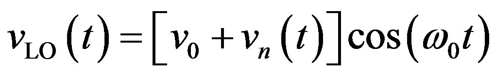
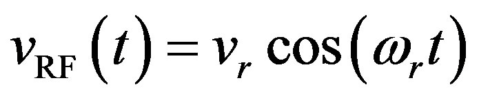 (1)
(1)
where , and
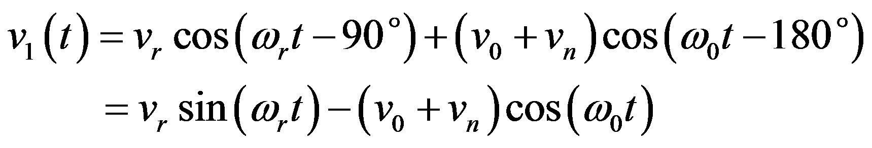
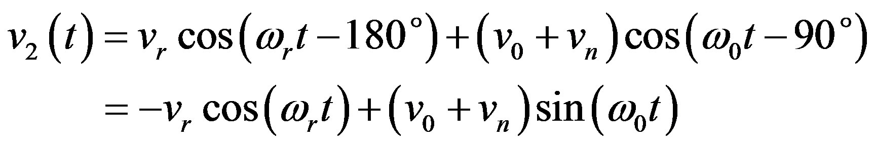
, and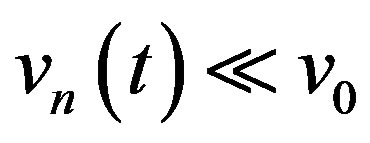 . If we have a 90˚ hybrid, the voltages across the two diodes are
 (2)
(2)
 (3)
(3)
The quadratic term of the diode V-I characteristic will give rise to the desired mixer products, so we will only consider this term and assume identical diodes so that diode currents can be represented as:
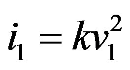 (4)
(4)
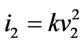 (5)
(5)
The negative term in Equation (4) accounts for the reversed polarity of the diodes. Using Equations (1) and (2) in Equations (3) and (4), gives
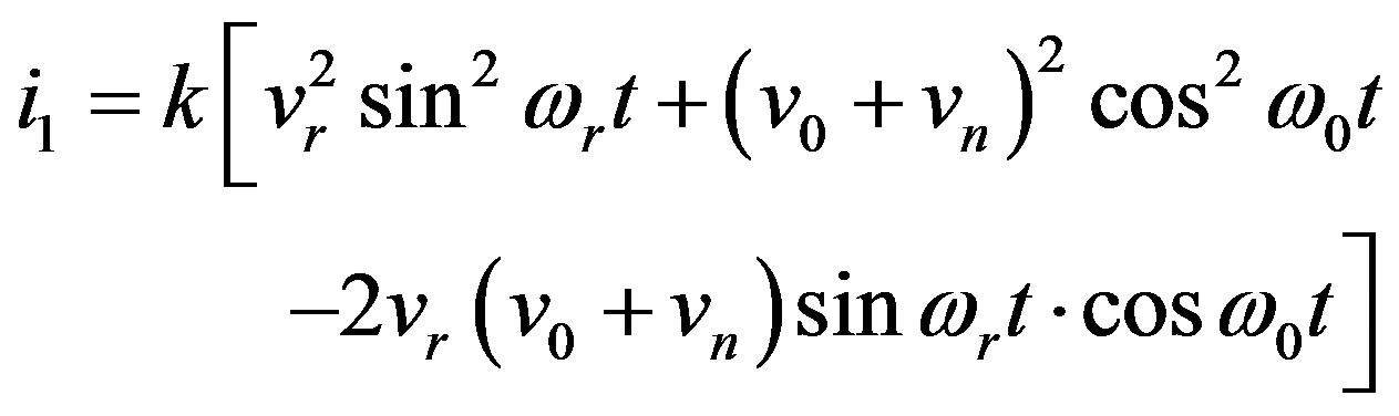 (6)
(6)
 (7)
(7)
After low pass filtering, the remaining terms will be DC, noise, and IF frequency terms.
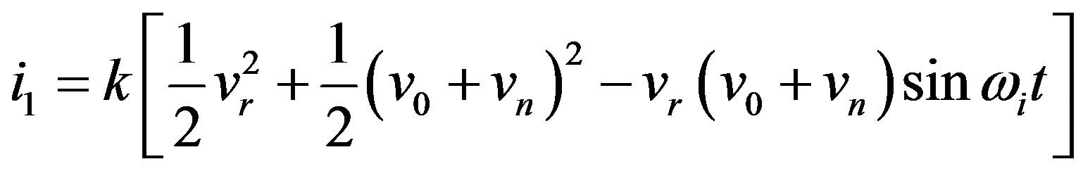 (8)
(8)
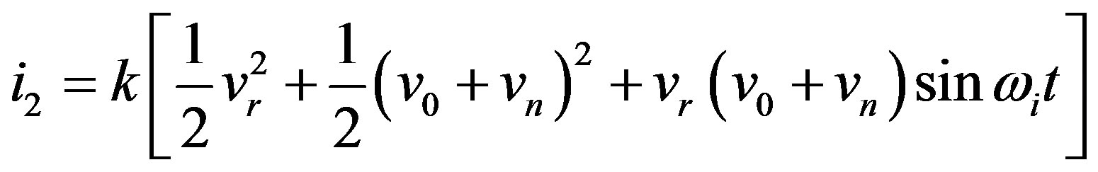 (9)
(9)
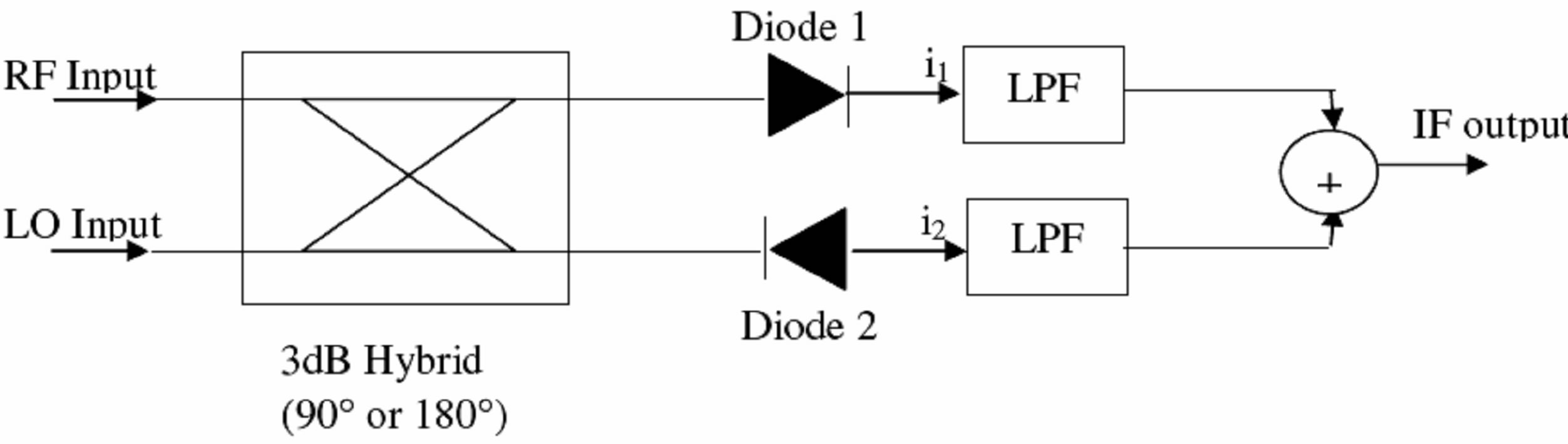
Figure 1. Single balanced mixer circuit.
where  is IF frequency. Combining above currents gives the IF output as
 (10)
(10)
since . This result shows that the first order terms in the noise voltages are cancelled by the mixer, while the desired IF signals combine in phase. Practical mixers can give 15 to 30 dB of AM noise rejection. Now consider the reflection of the input RF & LO signal from the diodes. If we have a balanced mixer with a 90˚ hybrid, the input RF signal gives rise to the following reflected waves (phasors) from the diodes:
 (11)
(11)
 (12)
(12)
where Γ is the reflection coefficient of each diode, Vr is the phasor RF input voltage. These two reflections will then arrive and combine back at the RF and LO input ports with the following amplitudes:
 (13)
(13)
 (14)
(14)
Thus the RF input is matched but the reflected wave appears at the LO port. Similarly when the LO port is driven, the reflected wave will appear at the RF port. So the RF and LO inputs of a mixer using a 90˚ hybrid will have good SWR characteristics. But the isolation between the RF and LO pots will be poor. Alternatively, if a 180˚ hybrid is used with the RF applied to the sum port and LO applied to the difference port, RF wave reflected from the diodes will be
 (15)
(15)
Then the reflections back at the sum and difference ports will be
 (16)
(16)
 (17)
(17)
the LO waves reflected from the diodes will be
 (18)
(18)
and the reflections back at the sum and difference ports will be
 (19)
(19)
In both cases the mismatch appears at the corresponding input port, while the RF and LO ports are isolated.
3. Specifications
3.1. Mixer Specifications
The specifications of the balanced Mixer, to be developed are:
RF Frequency: 12 - 18 GHz;
LO Frequency: 12 - 18 GHz;
IF Frequency: 500 MHz to 1500 MHz;
VSWR: 2:1;
LO Power: +10 dBm;
Conversion loss: <10 dB;
LO/RF/IF isolation: ≥20 dB;
RF/LO/IF Port: SMA connector.
3.2. Specifications of the Mixer Diode
Model No. MGS901;
IS = 1.6E–12 to 16E–12;
N = 1.35 - 1.45;
RS = 1.3;
CJO = 0.030E–12 to 0.060E–12;
VJ = 0.7;
M = 0.25;
EG = 1.43;
BV = 5 V & IBV = 10E–6;
TT = 3.0E–12.
3.3. Specifications of the Substrate
Substrate Name: RT Duroid;
Height of substrate (H): 10 mil (0.254 mm);
Dielectric constant (εr): 2.22;
Thickness of line (t): 17 µm.
4. Results
The present design is simulated using the HP-ADS2002 (Advanced Design System) PC-Tool for the microwave circuit simulation. ADS (Advanced Design System) is a fast general purpose RF and microwave circuit design, analysis and optimization program specifically developed to PCs. Harmonic balance simulation makes possible the simulation of circuits with multiple input frequencies. This includes intermodulation frequencies, harmonics, and frequency conversion between harmonics.
Figure 2 shows the S-parameter magnitude results of rat race coupler in decibel and Figure 3 shows the S-parameter phase results.
Figures 4 and 5 show the S-parameter magnitude results of low pass filter and DC coupler in decibel respec-
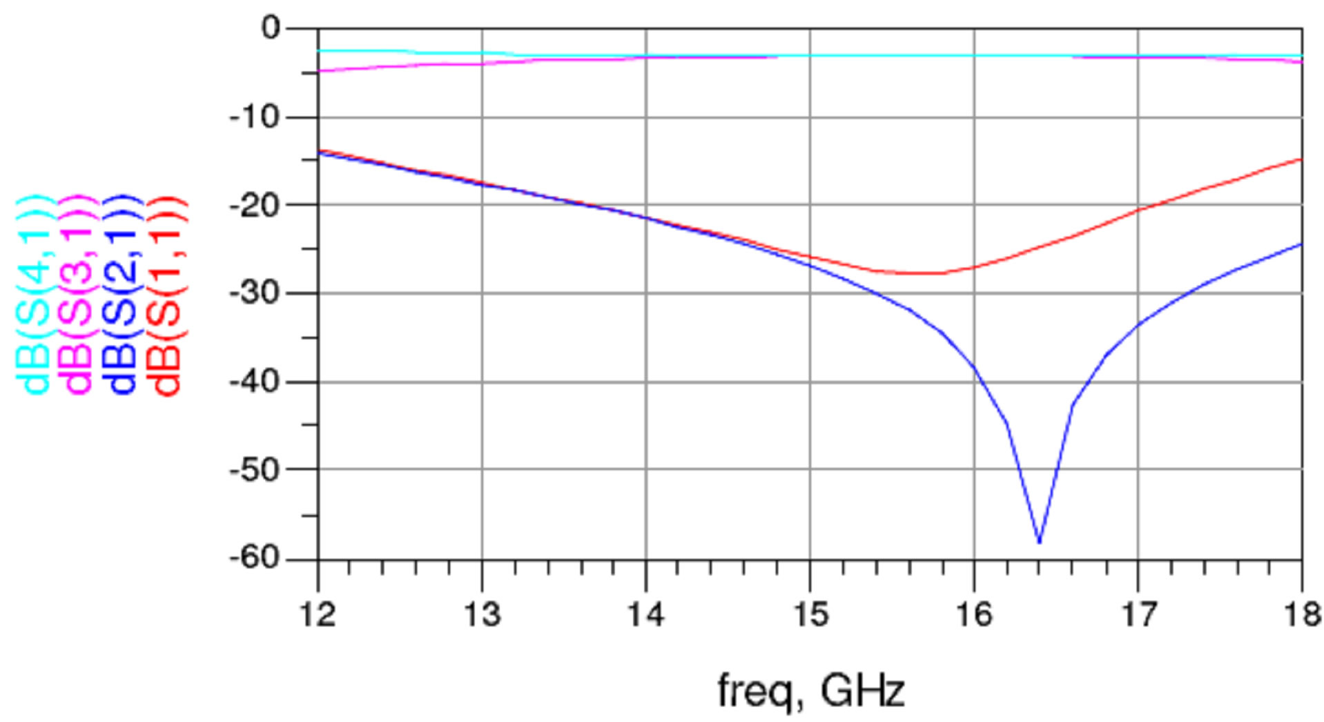
Figure 2. S-parameter magnitude (dB) results of rat race coupler.
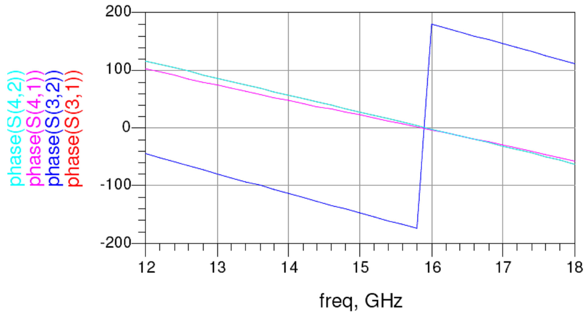
Figure 3. S-parameter phase results.
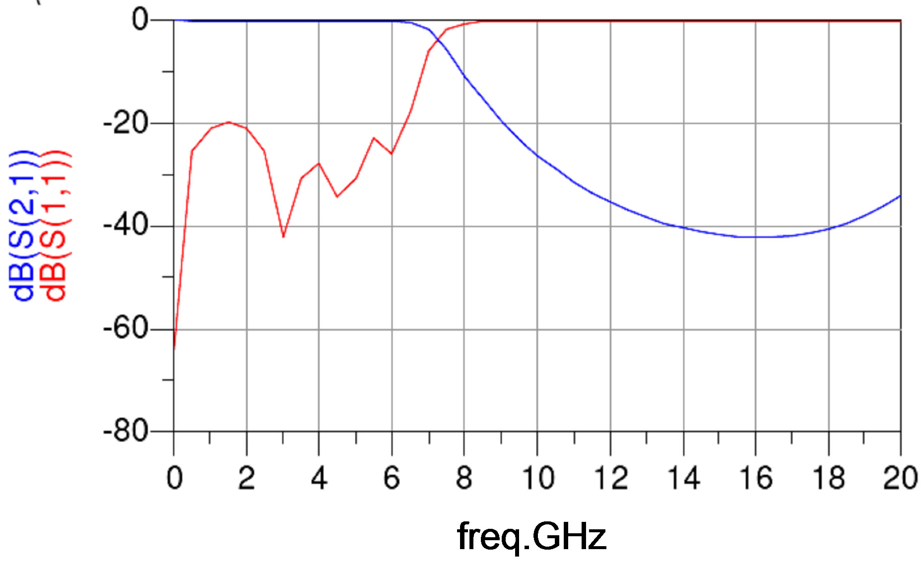
Figure 4. S-parameter magnitude (dB) results of low pass filter.
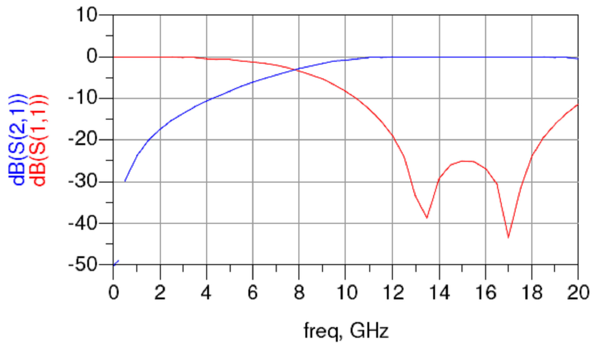
Figure 5. S-parameter magnitude (dB) results of DC coupler.
tively.
Figure 6 shows the S-parameter simulated result for conversion loss (dB) vs RF frequency (GHz) with LO Power = 10 dBm and IF Frequency = 1 GHz.
Figure 7 shows the S-parameter simulated results for conversion loss (dB) vs LO frequency (GHz) with LO power =10 dBm and IF frequency = 1 GHz.
Figure 8 shows the S-parameter simulated results for conversion loss (dB) vs IF frequency (GHz) LO power = 10 dBm and RF frequency = 33.25 GHz.
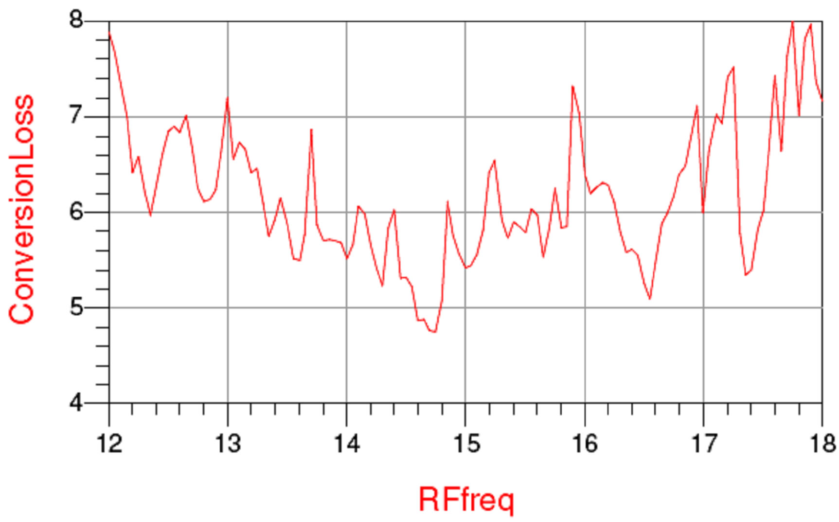
Figure 6. S-parameter simulated results for conversion loss (dB) vs RF frequency (GHz) LO power = 10 dB and IF frequency = 1 GHz.
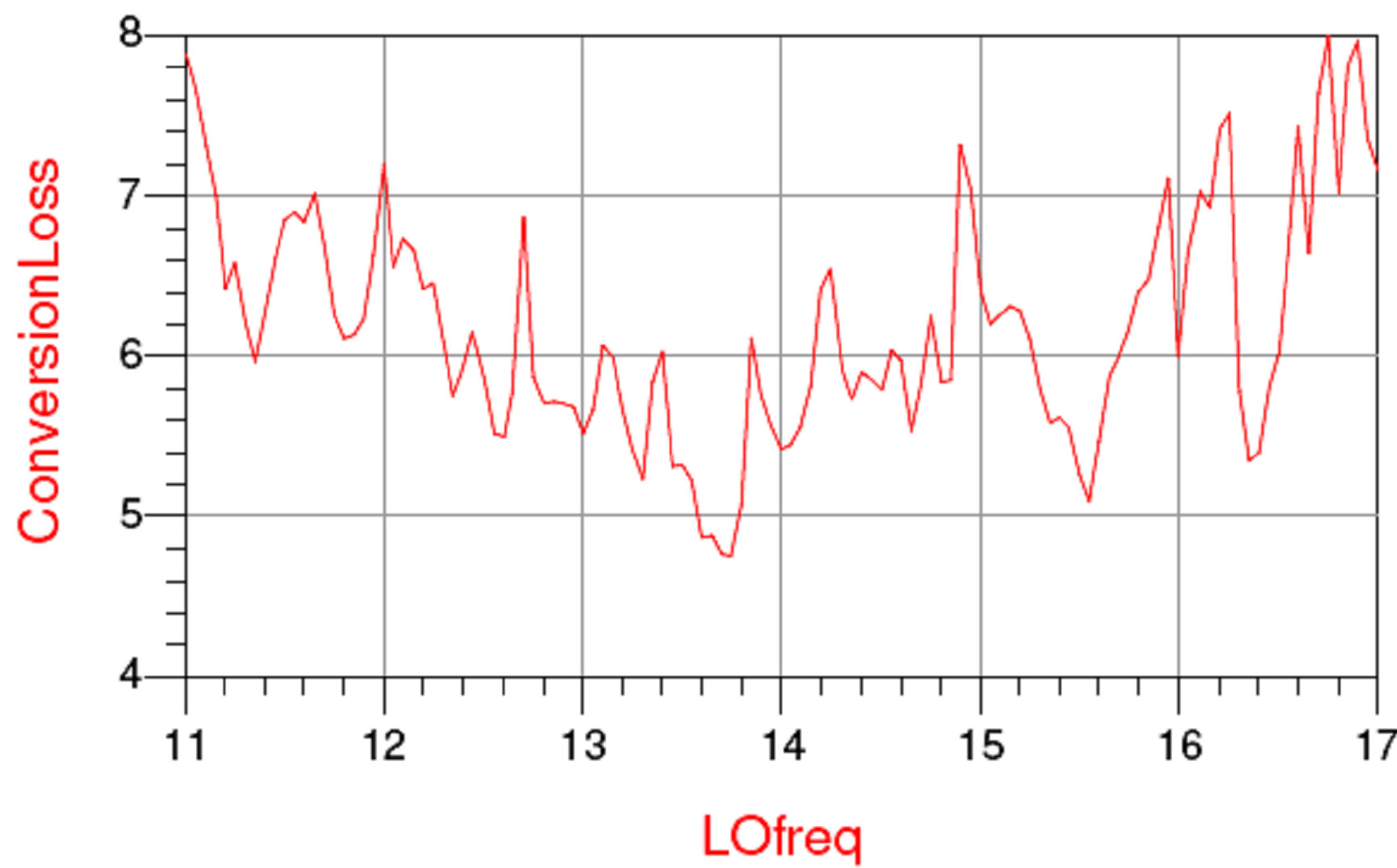
Figure 7. S-parameter simulated results for conversion loss (dB) vs LO frequency (GHz) LO power = 10 dBm and IF frequency = 1 GHz.
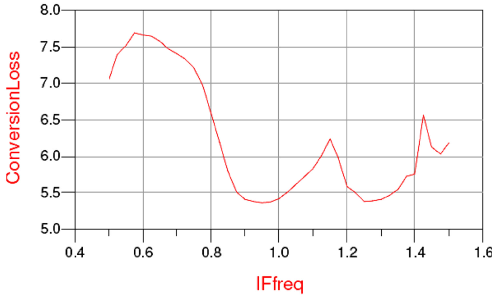
Figure 8. S-parameter simulated results for conversion loss (dB) vs IF frequency (GHz) LO power = 10 dBm and RF frequency = 33.25 GHz.
5. Conclusions and Future Scope
A Ku-Band mixer was designed, simulated and optimized using Agilent’s Advance Design System software. In mixers, the conversion loss is generally of the order of 10 dB in RF bandwidth [4-6]. Our aim was to minimize conversion loss over maximum RF bandwidth. The simulated mixer show conversion loss of less than 8 dB over the RF&LO frequency range 12 - 18 GHz and a minimum of 4.8 dB at 13.8 GHz. We also simulated conversion loss vs IF frequency. The achieved conversion loss over IF frequency range 500 MHz to 1500 MHz was less than 8 dB and a minimum of 5.3 dB at 950 MHz. Achieved results were better than the desired specification. All simulated performances are comparable to commercially available mixers at this frequency band [7-9].
Future plan includes minimizing LO power requirement by DC feeding the diode. We will also design and optimize double balanced mixers and active mixers in future and performance of these mixers will be compared with currently designed mixer.
REFERENCES
- D. M. Pozar, “Microwave Engineering,” 3rd Edition, John Wiley & Sons, Inc., Hoboken, 2005.
- B. Bhatt and S. K. Koul, “Stripline-Like Transmission Lines for Microwave Integrated Circuits,” John Wiley & Sons, Hoboken, 1989.
- S. A. Maas, “Microwave Mixers,” Artech House, Boston, 1986.
- J. E. Dalley, “A Strip-Line Directional Coupler Utilizing a Non-Homogeneous Dielectric Medium,” IEEE Transactions on Microwave Theory and Techniques, Vol. 17, No. 9, 1969, pp. 706-712. doi:10.1109/TMTT.1969.1127039
- G. Matthaei, L. Young and E. M. T. Jones, “Microwave Filters, Impedance Matching Networks, and Coupling Structures,” Artech House, Boston, 1983.
- J. paul, L. Yuan and P. Yen, “Beam Lead Dielectric Crossbar Mixers from 60 to 140 GHz,” IEEE MTT-S International Microwave Symposium Digest, Dallas, 15-17 June 1982, pp. 372-373.
- C. Nguyen and K. Chang, “140 GHz Broadband Crossbar Stripline Mixer with over 20 GHz Instantaneous RF Bandwidth,” Electronics Letters, Vol. 20, No. 11, 1984, p. 441.
- L. Q. Bui, N. Ton and D. Ball, “A D-Band MillimeterWave Crossbar Mixer,” IEEE MTT-S International Microwave Symposium Digest, San Francisco, 30 May 1984-1 June 1984, pp. 555-556.
- C. V. B. Maciel, D. F. M. Argollo and H. Abdalla Jr., “Broadside Suspended Stripline 3 dB Couplers,” Universidade de Brasilia, Brasili.