Energy and Power Engineering
Vol. 4 No. 3 (2012) , Article ID: 19020 , 5 pages DOI:10.4236/epe.2012.43021
Experimental Study on Vibration Control of Offshore Wind Turbines Using a Ball Vibration Absorber
School of Civil Engineering, Tongji University, Shanghai, China
Email: zzl_1116@126.com
Received January 5, 2012; revised February 20, 2012; accepted March 4, 2012
Keywords: Offshore Wind Turbine; Shake Table Test; Vibration Control; Ball Vibration Absorber
ABSTRACT
To minimize the excessive vibration and prolong the fatigue life of the offshore wind turbine systems, it is of value to control the vibration that is induced within the structure by implementing certain kinds of dampers. In this paper, a ball vibration absorber (BVA) is experimentally investigated through a series of shake table tests on a 1/13 scaled wind turbine model. The reductions in top displacement, top acceleration, bottom stress and platform stress of the wind turbine tower system subjected to earthquakes and equivalent wind-wave loads, respectively, with a ball absorber are examined. Cases of the tower with rotating blades are also investigated to validate the efficacy of this damper in mitigating the vibration of an operating wind turbine. The experimental results indicate that the dynamic performance of the tested wind turbine model with a ball absorber is significantly improved compared with that of the uncontrolled structure in terms of the peak response reduction.
1. Introduction
In the past two decades, offshore wind farms continue to grow rapidly throughout the world [1] . With the offshore wind turbine systems becoming taller and slender, the serviceability and safety may be considerably reduced due to concurrent wind and sea waves [2] . Moreover, many new offshore wind farms occurred in North America and Asia which are earthquake prone zones. The vibration of wind turbine towers during the earthquake or combined wind-wave loads may result in turbine damage or disfunction, causing great economical loss and social consequence. Under this background, to achieve tradeoffs between the safety and economical efficiency of large wind turbine systems, structural control that could suppress excessive responses might be a feasible option.
In the past four decades, the application of structural control techniques to mitigation of the dynamic response of civil engineering structures has been extensively studied. However, the potential of adopting structural control techniques in suppressing the excessive response of large offshore wind turbine systems has not been adequately explored. Up to now, only a few papers concerned with the use of external dampers in the vibration suppression of wind turbine towers are available. For instance, Argyriadis & Hille investigated the reduction of fatigue loading on a wind turbine with a pendulum tuned mass damper (TMD) by using a simple two-mass model [3] . Similarly, Faber and Dalhoff simulated the pendulum TMD, showing that it could considerably reduce the wind-induced response of the wind turbine [4] . However, the increase of the pendulum amplitude may cause collision between the tower and the pendulum. Ignoring the tower-blade interaction, Collins et al. studied optimal positioning of multiple TMDs on a wind turbine [5] . On the other hand, Murtagh and Basu took into account the tower-blade interaction and investigated the use of TMD for the mitigation of the along-wind forced vibration response of a simplified wind turbine [6] . However, the restriction of horizontal space in a wind turbine may make it impossible to implement a TMD or multi TMDs. Another vibration control device for wind turbine is tuned liquid column damper (TLCD), which was firstly introduced by Wilmink and Hengeveld [7] . They found that the TLCD provided significant damping with only 2% effective mass whereas for the same effect at least 4% effective mass were required in the classical pendulum dampers. Recently, Colwell and Basu examined the effectiveness of TLCD in reducing the dynamic response of offshore wind turbines under wind and wave forces [8] . The simulation results showed that the reduction of up to 55% the peak response might be achieved and conesquently the fatigue life of the wind tower will be significantly increased. However, the leak of liquid in the TLCD may be a hidden trouble for wind turbines.
The idea of the ball vibration absorber (BVA) emerged for the first time in Czech in 2000. This device has been adopted recently on two TV towers [9] . In this paper, a BVA is introduced for response suppression of offshore wind turbine systems. The focus of this paper is to experimentally investigate the efficacy of a BVA through a series of shake table tests on a 1/13 scaled wind turbine model. It is shown that implementing a BVA will significantly decrease the dynamic response of the wind turbine.
2. Shake Table Experiment
2.1. Shake Table Test
A shake table test was conducted to explore the response of a 1/13 scaled wind turbine model with or without a ball absorber fixed at the top of the nacelle. The experimental facility in the State Key Laboratory of Disaster Reduction in Civil Engineering at Tongji University is a 4.0 m × 4.0 m shake table with a capacity of 2.5 × 10⁴ kg. Motions containing frequencies up to 50 Hz can be simulated.
The tested wind turbine model is a 9.825 m high steel structure (Figure 1) which was designed to be a reduced scale model of a prototype 3.3 MW offshore wind turbine. The model is made up of four major parts, a base made from a 1.34 m × 1.34 m × 0.024 m steel plate, a 7.425 m high tubular steel tower composed of four segments, a nacelle of 0.92 m × 0.76 m × 0.46 m in size and three blades. Each of the blades is 2.4 m in length, 0.003 m in thickness, and has a rectangle section of 0.08 m × 0.04 m in size.
The testing data were recorded by an automatic data acquisition system. To capture the lateral response, uniaxial accelerometers and displacement transducers were installed on the turbine tower and the shake table.
One accelerometer, as well as a displacement transducer, was located on the top of the shake table. Five other accelerometers were located on the turbine tower, one at the base, one at the platform, one at the lower joint, one at the upper joint and one at the nacelle. Five other
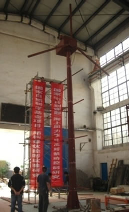
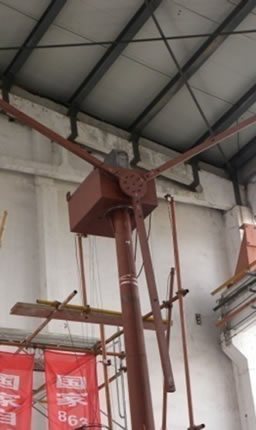
Figure 1. Photographs of the tested wind tower model.
displacement transducers were located at the same position as the accelerometers. Twelve strain gauges were located at different parts of the tower to measure the stress of the tower.
2.2. The Ball Vibration Absorber
The BVA consists of a steel ball, an arc path and two steel plates which prevent the ball from sliding aside (Figure 2). Between the ball and the arc path, a friction pad made from composite material is inserted. When subjected to a base excitation, the ball will roll along the surface of arc path, thus absorb the energy input into the structure through the motion of the ball and the friction effect between the ball and the friction pad. In the experiment, the device is mounted on the top of the nacelle.
It is planned to control the first mode of the structure. Therefore, the device is tuned into the fundamental frequency of the structure.
2.3. Experimental Test Program
In the tests, four time histories were used as excitations (Table 1), of which one was the 1999 Chi-chi earthquake record (CC for short), one was a ground motion generated by the physical random function model of ground motions (Wang for short) [10] , and the other two were wind-wave equivalent ground motions (DX1 and DX2 for short) generated by assuming the wind tower to be an equivalent SDOF system [11] . The fundamental idea of the load equivalence is that under the wind-wave load and the wind-wave equivalent ground motion, the tower has the same top displacement response. It should be noted that all the four excitations generated must be reproduced according to the time scale factor since the tested wind turbine was a scaled model. Cases of rotating


Figure 2. Photographs of the BVA.
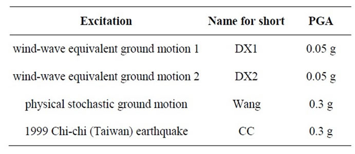
Table 1. Summary of excitations.
blades at different rotating speed (0 rpm, 4.8 rpm, 12 rpm) were also studied. Table 2 shows the total 20 cases carried out in the test. White noise in uncontrolled case is used for identification of the parameters of the tested structure.
The absolute accelerations measured at the shake table and their amplitude spectrums obtained by fast Fourier transform are examined. Here only the time histories and the amplitude spectrum of DX1 is presented in Figure 3.
2.4. Parameter Identification
The parameter of the tested wind turbine can be identified based on the measured frequency response functions. The curves in Figure 4 present the frequency-amplitude characteristics based on the 5 absolute acceleration records (from base to center of nacelle) in case 1 of white noise. The results show that the first natural frequency is 1.33 Hz (T = 0.75 s) and the second natural frequency is 6.64 Hz (T = 0.15 s). The half power method was used to estimate the modal damping from the frequency response function [12] . The method resulted in the first modal damping of 0.4% and the second modal damping of 0.06%, with which the damping matrix can be obtained using the Rayleigh damping model.
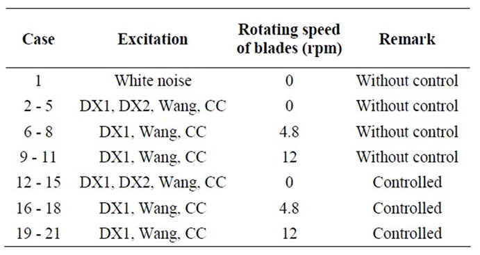
Table 2. Experimental program.
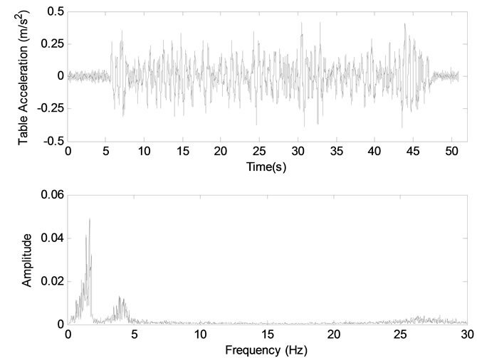
Figure 3. Measured table acceleration and its amplitude spectrums (DX1).
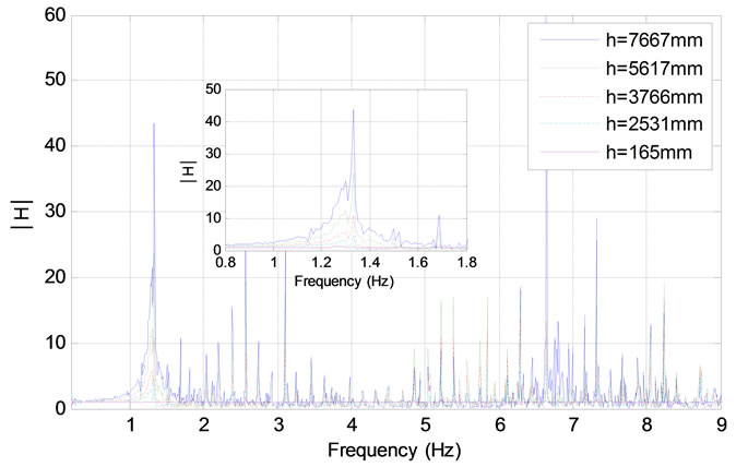
Figure 4. Recorded frequency response function.
3. Results of the Experiments
3.1. Wind Turbine with Parked Rotor
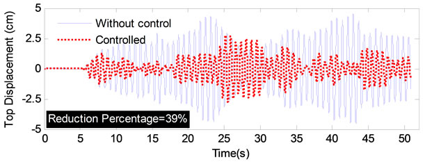
Vibration control experiments of the wind turbine model with parked rotor were firstly carried out. At this stage the blades kept still with one blade pointing downward, parallel to the tower. All the four excitations were imparted in the direction parallel to the rotor’s axis of rotation. The top displacement relative to table, absolute top acceleration, stresses at the bottom and the platform (the section near the lower joint of the tower) of the uncontrolled and ball absorber-controlled structure were measured. The stresses were converted from the measured strains by taking the elastic module as 2.06 × 10⁵ Mpa. The comparisons of the tested structure with and without control subjected to the excitations DX1, DX2, Wang and CC were carried out. For the length of the paper here only the results under DX1 were shown in Figure 5. The percentages in the black textbox at the figures indicate the peak response reduction by the BVA.
The improvement of the performance is evident from Figure 5, in which the peak response of the controlled structure is significantly suppressed compared to that of the uncontrolled structure. As shown in Table 3, the maximum response reduction varies from 15% - 53% for different excitation inputs. Generally speaking, the BVA is more effective when the wind turbine is subjected to the wind-wave equivalent loads than is subjected to the “pure” ground motions. This characteristic could be further interpreted by the difference between the frequency content of different inputs. Detailed analyses will be published elsewhere.
3.2. Wind Turbine with Rotating Blades
Experiments in operational conditions, with rotational speed of blades 4.8 rpm and 12 rpm, respectively, were then carried out. To obtain different rotational speeds, a transducer was used along with a motor fixed in the nacelle of the wind turbine. The maximum response reductions under different rotational speeds are illustrated in Table 4.
 (a)
(a) (b)
(b)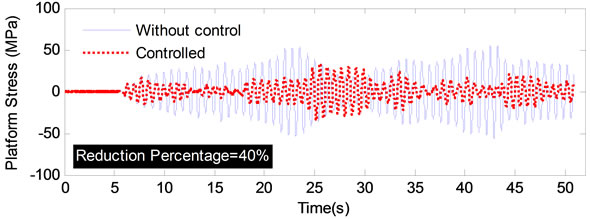 (c)
(c)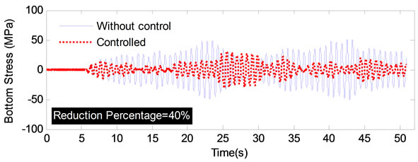 (d)
(d)
Figure 5. Comparison of structural response under DX1. (a) Top displancement; (b) Top absolute acceleration; (c) Platform stress; (d) Bottom stress.

Table 3. Maximum response reduction in parked condition.
From the results in Table 4, it is seen that the operation of the turbine may weaken the effectiveness of the damping device when the wind-wave equivalent load is used as input. Comparing Table 3 with Table 4, it is obvious that the response reductions under DX1 decrease from about 40% to about 25%. In contrast, for ground motions Wang and CC, the rotating of the blades will improve the effectiveness of the damping device in most cases.
In any case, the BVA can considerably suppress the dynamic response of the wind turbine whether the rotor is operating at the rotational speed of 4.8 rpm or 12 rpm.
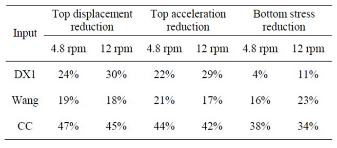
Table 4. Maximum response reduction in operational conditions.
4. Concluding Remarks
The effectiveness of the BVA is studied through a series of shake table tests on a 1/13 scaled wind turbine model under wind-wave equivalent loads and ground motions. The control device was installed on the top of the nacelle. Cases of the wind turbine in parked and operational conditions are investigated and the dynamic responses of the structure with or without control are compared. Based on the experimental study, the following concluding remarks can be made: 1) The BVA is consistently effecttive in mitigating the top displacement, top acceleration, platform stress and bottom stress of the wind turbine tower both under wind-wave equivalent loads and ground motions. The response reduction varies from 15% - 53% in different cases. But the damping device can inhibit a better performance when the structure is subjected to wind-wave equivalent loads. 2) When the turbine is in operational condition, the performance of the damping device is slightly different from the cases when the turbine is parked. For wind-wave equivalent loads, the operation of the turbine will weaken the effectiveness of the control device whereas it is opposite for ground motions.
5. Acknowledgements
Supports of the National Natural Science Foundation of China (Grant Nos. 90715033, 10872148 and 11172210), and the State Key Laboratory of Disaster Reduction in Civil Engineering (Grant Nos. SLDRCE08-A-01 and SLDRCE10-B-02) are greatly appreciated.
REFERENCES
- World Wind Energy Association, “World Wind Energy Report 2010,” WWEA, Bonn, 2011.
- L. Duenas-Osorio and B. Basu. “Unavailability of Wind Turbines due to Wind-Induced Accelerations,” Engineering Structures, vol. 30, No. 4, 2008, pp. 885-893. doi:10.1016/j.engstruct.2007.05.015
- K. Argyriadis and N. Hille, “Determination of Fatigue Loading on a Wind Turbine with Oil Damping Device,” Proceedings of the 2004 EUROPEAN Wind Energy Conference & Exhibition, London, 22-25 November 2004, pp. 1-6.
- T. Faber and P. Dalhoff, “Dynamic behavior of Oil Dampers in Wind Turbine Tower,” Germanischer Lloyd Wind Engerie GmbH, Hamburg, 2005.
- R. Collins, B. Basu and B. M. Broderick, “Optimal design of Multi-Tuned Mass Damper (MTMDS) for Wind Turbine Towers Using SSA,” Proceedings of the SECED Young Engineers Conference, Bath, 21-22 March 2005, pp. 1-8.
- J. P. Murtagh and B. Basu, “Along-Wind Response of a Wind Turbine Tower with Blade Coupling Subjected to Rotationally Sampled Wind Loading,” Engineering Structures, vol. 27, No. 8, 2005, pp. 1209-1219. doi:10.1016/j.engstruct.2005.03.004
- A. J. Wilmink and J. F. Hengeveld, “Application of Tuned Liquid Column Dampers in Wind Turbines,” Mecal Applied Mechanics BV, Enschede, 2005.
- S. Colwell and B. Basu, “Tuned Liquid Column Dampers in offshore Wind Turbines for Structural Control,” Engineering Structure, vol. 31, No. 2, 2008, pp. 358-368. doi:10.1016/j.engstruct.2008.09.001
- M. Pirner, “Actual behaviour of a Ball Vibration Absorber,” Wind Engineering and Industrial Aerodynamics, vol. 90, No. 8, 2002, pp. 987-1005. doi:10.1016/S0167-6105(02)00215-5
- D. Wang and J. Li, “Physical Random Function Model of Ground Motions for Engineering Purpose,” Science China Technological Sciences, vol. 54, No. 1, 2011, pp.175-182. doi:10.1007/s11431-010-4201-3
- X. Y. Bai, “Stochastic Optimal Control Analysis and Experimental Studies on Offshore Wind Turbine System,” Tongji University, Shanghai, 2011.
- G. Q. Li and J. Li, “Theory and application of Dynamic Testing on Engineering Structures,” Science Press, Beijing, 2002.