World Journal of Condensed Matter Physics
Vol.3 No.4(2013), Article ID:38949,5 pages DOI:10.4236/wjcmp.2013.34031
Cryocooler Operation of a Pulse-Driven AC Josephson Voltage Standard at PTB
![]()
Physikalisch-Technische Bundesanstalt, Quantum Electronics, Braunschweig, Germany.
Email: oliver.kieler@ptb.de
Copyright © 2013 Oliver F. O. Kieler et al. This is an open access article distributed under the Creative Commons Attribution License, which permits unrestricted use, distribution, and reproduction in any medium, provided the original work is properly cited.
Received September 6th, 2013; revised October 11th, 2013; accepted October 23rd, 2013
Keywords: Josephson Voltage Standard; Josephson Arbitrary Waveform Synthesizer (JAWS); SNS Josephson Junction; Cryocooler; Helium-Free Setup
ABSTRACT
The PTB Josephson Arbitrary Waveform Synthesizer (JAWS) enables the generation of arbitrary waveforms up to voltages of 70 mVRMS (199 mVPP) using two Josephson arrays in series containing 4000 Josephson junctions each. The SNS-like double-stacked junctions are based on NbxSi1−x as barrier material. While the JAWS system is typically operated using a Dewar with liquid helium, the operation in a closed-cycle pulse-tube cryocooler at temperatures around 4.2 K range was here investigated and successfully demonstrated. For this purpose a special designed cryoprobe was used to provide high quality pulses to the Josephson arrays.
1. Introduction
Pulse-driven Josephson junctions are the basis for one version of an AC Josephson voltage standard which enables the synthesis of arbitrary AC waveforms with extremely pure frequency spectra. Therefore, it is often called Josephson Arbitrary Waveform Synthesizer (JAWS). At present, three national metrology institutes develop and fabricate the required Josephson junction series arrays: NIST, AIST and PTB [1-4].
The operation of Josephson voltage standards is based on the Josephson effect (cf. [5] for more details and fundamentals). The JAWS contains Josephson arrays which work as quantizers for the generation of AC voltages resp. any desired waveform. To synthesize an arbitrary waveform with the JAWS, the waveform is transferred by analog-to-digital conversion (Ʃ∆-modulation) into a bit pattern (+1/0/−1). This pattern, containing positive and negative pulses with a non-constant pulse repetition frequency, is stored into the memory of a pulse pattern generator (PPG; we use one made by Sympuls AG Aachen1). The maximum clock frequency of our PPG is 15 GHz for return-to-zero pulses (i.e. a maximum data rate of 30 Gbit/s). The PPG is delivering the short current pulses (rise and fall time about 30 ps) to the Josephson arrays. At the array each current pulse causing the transfer of one flux quantum Ф0 = h/2e across each junction generating a voltage pulse (h/2e) i.e. the output voltage of the array is quantized.
For the application in the JAWS we use SNS-like Josephson junctions based on NbxSi1−x barriers at PTB [5, 6]. The junctions are arranged in double stacks to double the output voltage for a given design. The junctions are embedded into the center line of a 50 Ω coplanar-waveguide (CPW) to ensure high-quality pulse propagation along the array.
Our JAWS setup enables the synthesis of spectrally pure bipolar arbitrary waveforms with a signal-to-noise ratio of up to 120 dBc. As already demonstrated, amplitudes of up to 184 mVRMS (521 mVpp) can be generated for DC-voltages and AC-voltages in a frequency range from 60 Hz to 1 MHz by connecting two arrays in series with 12,000 Josephson junctions in total (see Figure 1) [7]. The output voltage can be adjusted very precisely by changing the pulse density in the Ʃ∆-coded waveform while the number of junctions in the array remains constant. Typically, maximum Ʃ∆-code amplitudes of AƩ∆ = 0.9 are possible. In this paper, we use two Josephson arrays containing 4000 junctions each. Previous to op-
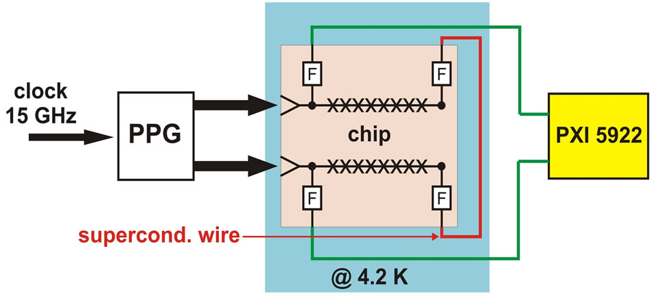
Figure 1. Simplified experimental setup of the JAWS using two arrays in series connected with a superconducting wire and operated with a PPG.
eration of the arrays in a cryocooler, we characterized these arrays in a Dewar with liquid helium (LHe) at temperature T = 4.2 K: the critical current is Ic ≈ 3.5 mA for each array and the normal resistance is Rn ≈ 4.4 mΩ for a single junction. The arrays are able to generate pure waveforms up to 70 mVRMS (199 mVPP) each with a Ʃ∆-code amplitude of AƩ∆ = 0.8. By mounting the JAWS chip in a specially designed cryoprobe we investigated the opportunity to operate this JAWS array with a pulse tube cryocooler. This operation mode without the need of liquid helium is desired for prospective applications and easy operation of the JAWS.
Recently, Urano et al. operated the Josephson arrays of an optoelectronics JAWS system in a two stage Gifford-MacMahon refrigerator [8]. They demonstrated the synthesis of AC waveforms with voltages below 1 mVRMS and higher harmonics suppressed by −80 dBc at most.
2. Experimental Setup
The main components of the experimental setup for the cryocooler operated JAWS are the same than for the LHe-operated system explained in detail in [5,9]. The main difference is the adapted cryoprobe. Some details of the setup are briefly described in this section. Two arrays are integrated on a 10 mm × 10 mm silicon chip. The JAWS chip is mounted onto a chip carrier (23 mm × 40 mm) based on Rogers RO30061. The conducting CPW paths of this carrier are made of copper with a 2 µm gold layer on top (without nickel). The CPW lines of this carrier are connected to two PCB-SMA launchers. Two semi-rigid cables (length about 1 m) are connected to these launchers and fed through the inner tube of the cryoprobe to the probe head. The cryoprobe contains eight isolated DC-lines in total to deliver a compensation signal [10] to the two arrays and to measure the output AC voltage. The cryoprobe is equipped with three thermal radiation shields and a magnetic shielding tube. Additionally, a temperature sensor is integrated, which is located about 8 cm away from the chip carrier.
The cryocooler is a closed-cycle pulse tube refrigerator (Oxford Instruments Optistat PTR-TL41) with top loading sample assembly. The base temperature of this cryocooler is about 3.5 K with a nominal cooling power of 1 W at 4 K. The advantages of this system are the quite large sample space (diameter 50 mm), the rather short cool down time of about 4 hours and the low vibration of the setup. A photograph of the whole setup (JAWS electronics and cryocooler) is shown in Figure 2.
3. Measurements in the Cryocooler
After mounting the JAWS chip in the cryocooler, the current-voltage characteristics of the two Josephson arrays at 4.2 K are unchanged compared to the measurements in liquid helium: the critical current is Ic ≈ 3.5 mA and the normal resistance is Rn ≈ 4.4 mΩ. As expected, the dc characteristics of the Josephson arrays are not affected by their operation in the cryocooler.
Then, we investigate the behavior under pulse operation. The correct operation of the JAWS is often proven by measuring frequency spectra of simple synthesized waveforms; the JAWS system works well, when all higher harmonics are completely suppressed. Figure 3 illustrates the frequency spectrum (upper graph) and the time-domain signal (lower graph) of a synthesized bipolar sinusoidal waveform with a frequency of 3750 Hz and an amplitude of 70.2 mVrms (199 mVPP) at a temperature of 4.7 K. The spectra were measured using a fast digitizer (NI-PXI 59221) operated on batteries to avoid any noise from the power line. The high noise floor in our lab (cf. inset of Figure 3) prevents the direct measurement of the pure spectra we typically observe with liquid helium measurements performed in another laboratory [11]. The pure spectrum of the upper graph was achieved by subtracting the noise floor (when the JAWS signal is switched off) from the measured waveform. Higher harmonics are not visible above the noise floor, i.e. they are suppressed by at least −107 dBc. The inset in the upper graph shows the measured JAWS signal and the noise floor separately, indicating that the distortion tones (especially at frequencies around 15 kHz) are not related to the JAWS signal. The time-domain signal of the lower graph shows the measured signal directly.
The high noise floor is indicating that the shielding of our setup is not sufficient to suppress the influence of the noisy environment in this laboratory building. By switching off all electrical devices of the JAWS and even the cryocooler (including the compressor) in our laboratory the noise floor was not influenced at all. Therefore the noise seems to be caused by external sources. Unfortunately the cryocooler cannot be moved to a shielded laboratory. At least it was possible to check the mobile JAWS setup and the cryoprobe in such a shielded laboratory in liquid helium. Here, no distortion tones were visible in the noise floor. The operation margins of both
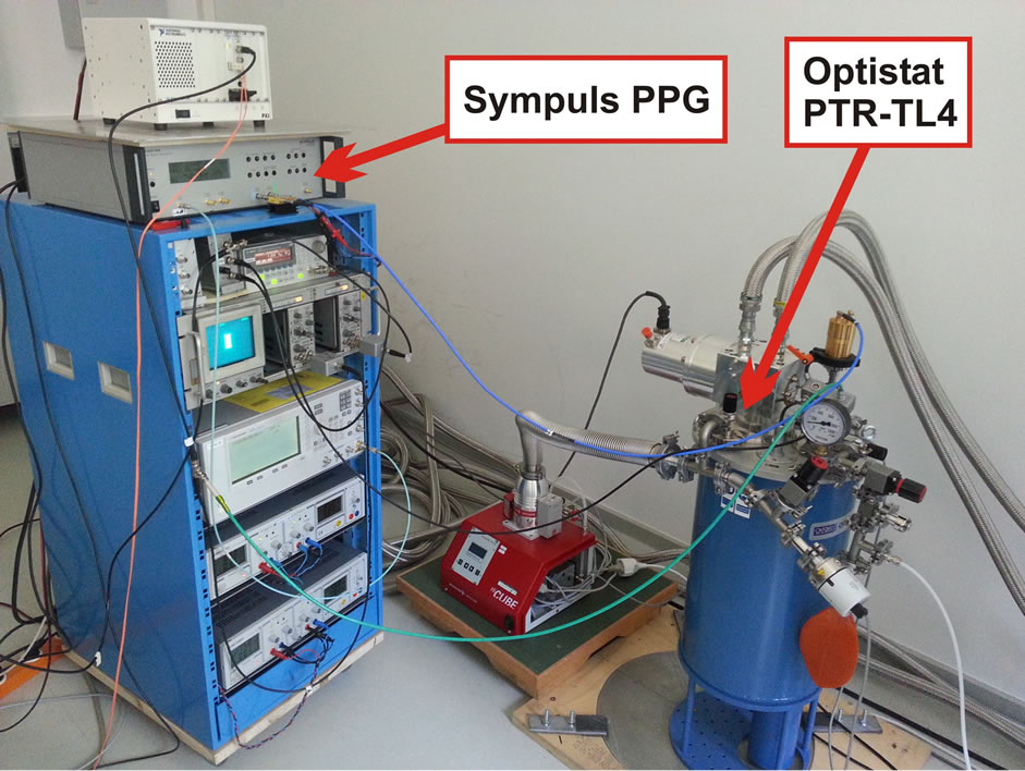
Figure 2. Photograph of experimental setup showing the JAWS electronics and the cryocooler Optistat PTR-TL4 from Oxford Instruments1.
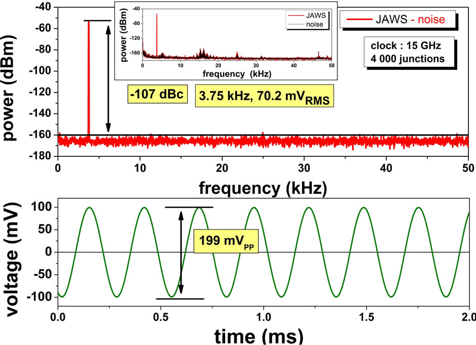
Figure 3. Frequency-spectrum (upper graph) and timedomain (lower graph) of a synthesized sinusoidal waveform with a frequency of 3750 Hz and an amplitude of about 70.2 mVRMS (199 mVPP) measured at 4.7 K. The noise floor was subtracted from the frequency spectrum in the upper graph. The inset shows the JAWS signal and the noise floor separately.
arrays are remaining mainly unchanged when performing the measurements in the cryocooler rather in LHe.
The cryocooler allows the adjustment of different temperatures by controlled heating with a nominal temperature stability of about 5 mK under unloaded conditions. It was possible to achieve operation margins under pulse drive (small but stable: e.g. current margins of about 100 µA) up to temperatures of about 5.6 K (measured at the cryoprobe temperature sensor). At this temperature the critical current was reduced to about 0.8 mA from 3.5 mA at 4.2 K. The operation margins were proportionately reduced too. For temperatures above 5.6 K the higher harmonics were not fully suppressed anymore, indicating that there are no operation margins. Figure 4 shows the frequency spectrum and the time domain sig-
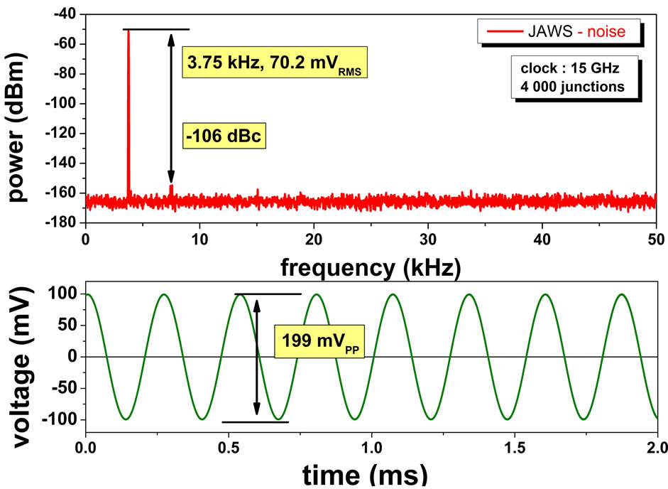
Figure 4. Frequency-spectrum (upper graph) and timedomain (lower graph) of a synthesized sinusoidal waveform with a frequency of 3750 Hz and an amplitude of about 70.2 mVRMS (199 mVPP) measured at 5.7 K. The noise floor was subtracted from the frequency spectrum in the upper graph (cf. Figure 3). Higher harmonics are suppressed by at least 106 dBc but visible above the noise floor.
nal of a 3750 Hz synthesized sine wave at an operation temperature of 5.7 K. Although the first harmonic is not fully suppressed at this temperature, a very good signalto-noise ratio of −106 dBc is still achieved.
The results clearly demonstrate that a stable operation of the JAWS system in this cryocooler is possible using our purpose-built cryoprobe also for temperatures above 4.2 K. The temperature stability at the JAWS chip is sufficient to ensure stable operation margins even in pulse mode operation. The cycle frequency of the cold head of about 1 Hz was not visible in the measured signal.
Figure 5 shows the current-voltage characteristic (IVC) for different pulse amplitudes (in steps of 250 a.u.) at a constant pulse repetition frequency of 15 GHz at 4.2 K. For clarity the different IVCs are shifted. The PPG amplitudes are given in arbitrary units with a value of 4,000 corresponding to a pulse amplitude of about 0.5 VPeak. Additional broad band amplifiers (Picosecond 58821) with a gain of 16 dB are mounted to the PPG outputs. It is clearly visible, that the width of the critical current (or zero Shapiro step, 0. SS) is reduced with increasing microwave power, while the first Shapiro step (1. SS) is increasing. In the pulse mode operation with applied compensation signal [10] and non constant pulse repetition frequency, typical amplitudes of about 1500 a.u. are used. Figure 6 shows the same IVC for a temperature of 5.6 K indicating the reduced critical current and Shapiro step widths due to the high temperature. Consequently, less microwave power was necessary in pulse mode operation—here typically an amplitude of about 1000 a.u. is applied.
Figure 7 shows the temperature dependences of the critical current and of the normal resistance (calculated at
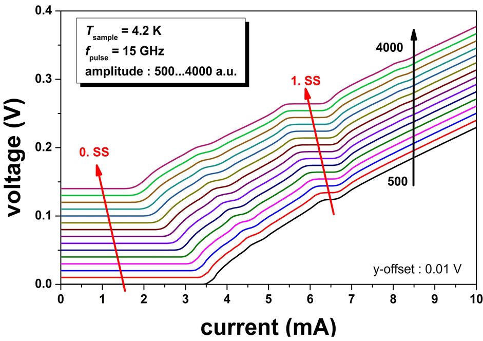
Figure 5. Current-voltage characteristics for different pulse amplitudes at a constant pulse repetition frequency of 15 GHz at 4.2 K. For clarity the different IVCs are shifted.
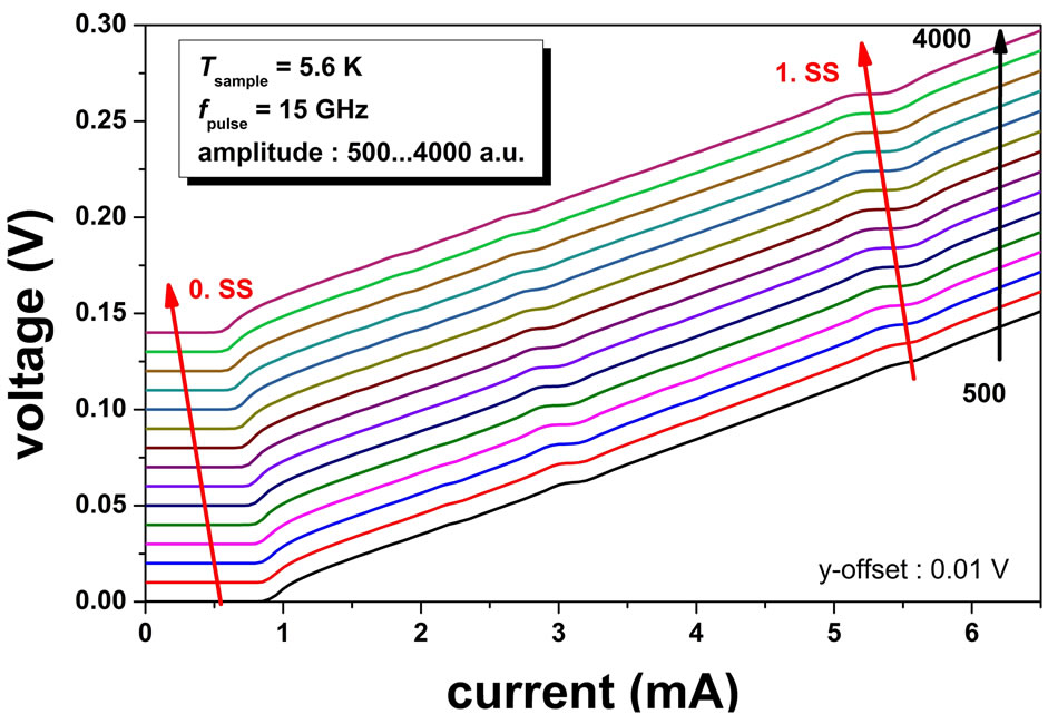
Figure 6. Current-voltage characteristics for different pulse amplitudes at a constant pulse repetition frequency of 15 GHz at 5.6 K. For clarity the different IVCs are shifted.
2Ic) of the Josephson array. At a temperature of about 8.4 K the critical current is nearly zero. The shown value of 1 µA is the lower measurement limit of the sourcemeasure-unit used. The jump in the normal resistance at a temperature of about 9.1 K shows the critical temperature of the niobium electrodes of the Josephson junctions. This temperature was calculated using the mean value of our two temperature sensors: cold head and cryoprobe. The JAWS chip is arranged in the middle between these two sensors. Therefore this method is convenient for a first estimation of the “real” chip temperature, even if the temperature difference between these two sensors is about 0.2 K at 4.2 K and 0.04 K at 10 K. During the automated measurement the temperature was controlled to be stable within 0.01 K.
As the JAWS chip contains two Josephson arrays, the temperature dependence of the critical current of one array can be used as a temperature sensor (detector array) for the second array. A more detailed evaluation of the temperature behavior during pulse operation of the sec-
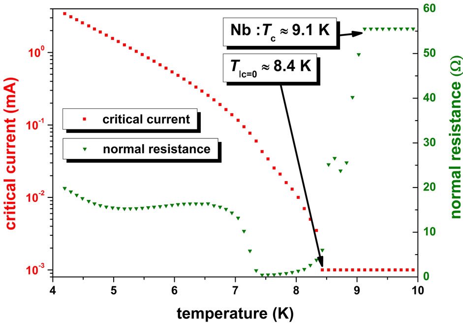
Figure 7. Temperature dependences of the critical current and of the normal resistance (calculated at 2Ic) of the Josephson array. At 8.4 K the critical current of the Josephson junctions vanished. The jump in normal resistance is indicating the critical temperature of the niobium at about 9.1 K.
ond array is possible now. For example, we operated the JAWS chip at 4.2 K with a critical current Ic ≈ 3.5 mA. By applying a typical pulse amplitude of 2000 a.u. (for positive and negative pulses) to the second array with a maximum and constant pulse repetition frequency of 15 GHz, the critical current of the detector array dropped to a constant value of Ic = 2.7 mA indicating a chip temperature of 4.4 K. This means, that the temperature was increased about ∆T = 0.2 K during the measurement. The temperature sensor of the cryoprobe showed a temperature difference of only ∆T = 0.02 K. We repeated this measurement for a maximum pulse amplitude of 4000 a.u. and measured a drop of the critical current to Ic = 2.1 mA corresponding to a temperature of 4.6 K, i.e. a temperature difference of ∆T = 0.4 K (cryoprobe temperature sensor: ∆T = 0.05 K). These results clearly indicate that the temperature sensor of the cryoprobe significantly underestimate the temperature increase of the JAWS chip under pulse operation. This is probably caused by the distance to the chip and by the fact that the heat generation on the chip takes place in a limited space with a rather low specific heat capacity. The compensation signal is not influencing the temperature in the system at all.
In the recent paper by Urano et al. [8] presenting a two stage Gifford-MacMahon refrigerator for the operation of their JAWS system, a resistive heater on the chip was used to stabilize the temperature and to avoid a hysteresis in the current-voltage characteristic. Such a hysteresis was not observed in our setup. As Urano et al. [8] did not embed a thermometer on the chip, the actual temperature was not monitored or evaluated consequently.
4. Summary
This paper describes the operation of Josephson arrays of the PTB JAWS system in a closed-cycle pulse tube refrigerator. The temperature stability at the JAWS chip is sufficient to ensure stable operation margins even in pulse mode operation. Using Josephson arrays with 4000 Josephson junctions stable margins were possible for the generation of AC voltages up to 200 mVPP and temperatures of up to 5.6 K.
5. Acknowledgements
The authors would like to thank R. Behr, L. Palafox, Th. Weimann, F. Müller, R. Wendisch, B. Egeling, P. Hinze, K. Störr for technical assistance, discussions, and comments.
This work was partly carried out with funding by the European Union within the EMRP JRP SIB59 Q-WAVE. The EMRP is jointly funded by the EMRP participating countries within EURAMET and the European Union.
REFERENCES
- S. P. Benz and C. A. Hamilton, “A Pulse-Driven Programmable Josephson Voltage Standard,” Applied Physics Letters, Vol. 68, No. 22, 1996, pp. 3171-3173. http://dx.doi.org/10.1063/1.115814
- S. P. Benz, P. D. Dresselhaus, C. J. Burroughs and N. F. Bergren, “Precision Measurements Using a 300 mV Josephson Arbitrary Waveform Synthesizer,” IEEE Transactions on Applied Superconductivity, Vol. 17, No. 2, 2007, pp. 864-869. http://dx.doi.org/10.1109/TASC.2007.898138
- C. Urano, N. Kaneko, M. Maezawa, S. Gorwadkar, T. Itatani, H. Saitou, J. Maeda and S. Kiryu, “Operation of Josephson Junctions with Current Pulses Generated by Triggering a Cold Photo Detector with an Optical Comb,” IEEE Transactions on Applied Superconductivity, Vol. 17, No. 2, 2007, pp. 870-873. http://dx.doi.org/10.1109/TASC.2007.897391
- O. Kieler, R. Iuzzolino and J. Kohlmann, “Sub-µm SNS Josephson Junction Arrays for the Josephson Arbitrary Waveform Synthesizer,” IEEE Transactions on Applied Superconductivity, Vol. 19, No. 3, 2009, pp. 230-233. http://dx.doi.org/10.1109/TASC.2009.2019283
- R. Behr, O. Kieler, J. Kohlmann, F. Mueller and L. Palafox, “Development and Metrological Applications of Josephson Arrays at PTB,” Measurement Science and Technology, Vol. 23, No. 12, 2012, Article ID: 124002. http://dx.doi.org/10.1088/0957-0233/23/12/124002
- F. Müller, T. Scheller, R. Wendisch, R. Behr, O. Kieler, L. Palafox and J. Kohlmann, “NbSi Barrier Junctions Tuned for Metrological Applications up to 70 GHz: 20 V Arrays for Programmable Josephson Voltage Standards,” IEEE Transactions on Applied Superconductivity, Vol. 23, No. 3, 2013, Article ID: 1101005. http://dx.doi.org/10.1109/TASC.2012.2235895
- O. Kieler, R. Behr and J. Kohlmann, “Development of a Pulse-Driven AC Josephson Voltage Standard at PTB,” Proceedings of the International Superconductive Electronics Conference ISEC, Cambridge, 7-11 July 2013, pp. 59-61
- C. Urano, M. Maruyama, N. Kaneko, H. Yamamori, A. Shoji, M. Maezawa, Y. Hashimoto, H. Suzuki, S. Nagasawa, T. Satoh, M. Hidaka and S. Kiryu, “Operation of a Josephson Arbitrary Waveform Synthesizer with Optical Data Input,” Superconductor Science and Technology, Vol. 22, No. 11, 2009, Article ID: 114012. http://dx.doi.org/10.1088/0953-2048/22/11/114012
- O. Kieler, D. Schleußner, R. Behr and J. Kohlmann, “Improved Setup for Pulse-Driven AC Josephson Voltage Standards,” Proceedings of the International Superconductive Electronics Conference ISEC, Fukuoka, 16-19 June 2009.
- S. P. Benz, C. J. Burroughs and P. D. Dresselhaus, “AC Coupling Technique for Josephson Waveform Synthesis,” IEEE Transactions on Applied Superconductivity, Vol. 11, No. 1, 2001, pp. 612-616. http://dx.doi.org/10.1109/77.919419
- O. Kieler, R. Behr, D. Schleussner, L. Palafox and J. Kohlmann, “Precision Comparison of Sine Waveforms with Pulse-Driven Josephson Arrays,” IEEE Transactions on Applied Superconductivity, Vol. 23, No. 3, 2013, Article ID: 1301404. http://dx.doi.org/10.1109/TASC.2013.2237817
NOTES
1Commercial instruments are identified in this paper in order to adequately specify the experimental procedure. Such identification does not imply recommendation or endorsement by PTB.