International Journal of Astronomy and Astrophysics
Vol.3 No.2A(2013), Article ID:33319,12 pages DOI:10.4236/ijaa.2013.32A007
Gravity Caused by TEM Waves Operating on Dipoles in Atoms
Uppsa Research, Gnesta, Sweden
Email: hans@miklagaard.com
Copyright © 2013 Hans W Giertz. This is an open access article distributed under the Creative Commons Attribution License, which permits unrestricted use, distribution, and reproduction in any medium, provided the original work is properly cited.
Received February 24, 2013; revised March 25, 2013; accepted April 3, 2013
Keywords: Gravity; Gravitation; Poynting Vector; Elementary Particle; Dipole; TEM Waves
ABSTRACT
The study displays the existence of a gravitational singularity in the universe generating synchronized and extremely low frequency plane TEM (transverse electromagnetic) waves. It is proposed that atomic intrinsic electromagnetic fields create resonance with these plane TEM waves, causing atoms to receive and to re-emit synchronized plane TEM waves. The energy flow of synchronized plane TEM waves, travelling in opposite directions between e.g. two atoms, creates mutual force of attraction, i.e. gravity. Consequently, gravity is not an intrinsic atomic feature; however, the result of passive atoms exposed to electromagnetic energy. The study describes how plane TEM waves emitted by the gravitational singularity were measured. The study also displays how gravity from the earth, moon, sun and the gravitational singularity was measured and how gravity was simulated using an electronic device. The present electromagnetic law of gravity is compared with Newtonian geometric law of gravity.
1. Introduction
Newton made the geometric description of gravity. Despite elapsed time the theoretical description of gravity remains unsolved.
It’s known that the atom contains charge, static electricand magnetic dipole moment. These fields decrease with the square of the distance and can consequently not create gravity. It seems unlikely that the atom generates alternating electromagnetic fields by itself, and hence electromagnetic energy is often ruled out as the origin of gravity. The prevailing track is to explain gravity with string theory [1,2].
The present study builds on the observation that gravity comprises plane TEM (transverse electromagnetic) waves or energy. The theory of plane TEM waves is well known and hence, it is possible to describe gravity entirely by the laws of electromagnetism. All theory is found in university grade textbooks [3,4]. TEM waves can also be explained by its photon according to the wave-particle duality [5,6]. In the present paper the gravitational energy is described by the plane TEM wave.
The study builds on the observation that the universe contains one generator emitting plane TEM waves. All emitted plane TEM waves are quasi synchronized, facilitated by its extremely low frequency and origin. This generator or gravitational singularity can consist of circulating charge and is called the Gravity Source in the present study.
Electric, E, and magnetic, B, field vectors are linked in plane TEM waves and in this case they are almost static. An atomic elementary entity that contains a static electric field, Ei, merged with a static magnetic field, Bi, creates resonance with this type of plane TEM waves; it receives plane TEM waves and re-emits them without changing content. It is called MQ (mass quantum) in the present study.
In order to illustrate the simplicity of gravity a grossly simplified universe is described. This simplified universe contains a Gravity Source and only two MQs, MQ1 and MQ2. The Gravity Source emits plane TEM waves, TEM1, to MQ1. MQ1 creates resonance, receives and re-emits TEM1 uniformly in space and where a part is received by MQ2. MQ2 creates resonance, receives and re-emits TEM1 uniformly in space and where a part is received by the Gravity Source. Simultaneously the Gravity Source emits plane TEM waves, TEM2, to MQ2, MQ2 re-emits a part to MQ1 and MQ1 re-emits a part to the Gravity Source. Consequently, this simplified universe contains circulating, synchronized plane TEM waves travelling in opposite directions between the Gravity Source, MQ1 and MQ2. According to the laws of electromagnetism, synchronized plane TEM waves travelling in opposite directions create mutual force of attraction, i.e. gravity. This model can be scaled up to any number of MQs, e.g. to today’s universe.
In the present study the hypothesis is that gravity is electromagnetic energy generated centrally in the universe, distributed within the universe, received and reemitted by fully passive atoms or MQs (mass quanta) in atoms.
This theory was verified in Section 2. Synchronized, plane TEM waves travelling in opposite direction were mapped on the laws of electromagnetism. It resulted in an equation describing the relation between the number of involved MQs, their distance and the mutual force of attraction. This relationship can be called the electromagnetic law of gravity and which was compared with the Newtonian geometric law of gravity.
Section 3 describes an electronic device that simulated the MQ. This device was used in Section 4 in order to empirically verify the theory in Section 2. Measurements were made according to a method described in [7]. Section 3 also describes an electronic device that contained a static magnetic field merged to an alternating electric field and where the frequency of this field was adjusted to the frequency of plane TEM waves emitted by the Gravity Source. It facilitated measurement of the Gravity Source frequency.
Section 5 covers discussion and where the measured (gravity) TEM wave’s characteristics are mapped on the atom’s nucleus, traditionally described by the Standard Model [8,9]. It results in a better understanding of the atom. The position of the earth’s rotational axis relative to the Galactic Centre [10,11] and the Gravity Source is discussed based on data obtained from WMAP and the Planck mission [12], indicating the huge influence of the Gravity Source on the entire universe.
Conclusions are made in Section 6.
Aim of the study: the aim of the study is to present and to verify a theoretical model of gravity.
2. Theoretical Model of Gravity
Maxwell’s equations  and
and  result in plane TEM (transverse electromagnetic) waves [3]. This is the most common electromagnetic energy in the universe resulting in e.g. radio waves, light and X-rays depending on frequency.
The behavior and characteristics of plane TEM waves is independent of its frequency. The field vectors E and B or  are linked and perpendicular. The field vector amplitudes relate as
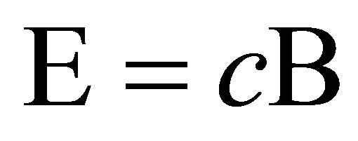 , where c is the speed of light. The electric and magnetic field vector amplitudes E and B decrease with the distance from the source as 1/r. The Poynting vector S describes the TEM energy flow density [4]
 (1)
(1)
The energy stored in the magnetic field is just equal to that in the magnetic field. The direction of energy flow is reversed for a wave travelling in the opposite direction because the phase of E and H is reversed.
Assume that one source, Source 1, radiates plane TEM1 waves, described by its Poynting vector 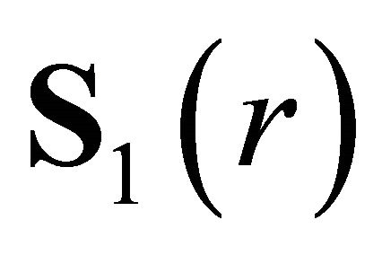 at the distance r from Source 1. Source 2 is positioned at the distance r. Source 2 is switched on whereby it radiates plane TEM2 waves uniformly. In the direction towards Source 1 plane TEM1 and TEM2 waves interact because of the force between their synchronized field vectors. This also implies that there is energy transfer from TEM1 to TEM2 when TEM2 propagates towards Source 1. In equilibrium there is energy transfer in both directions, i.e. from TEM1 to TEM2 vice versa. Note that E and H are always perpendicular and hence
  can be replaced by
 . Equilibrium is defined by the amount of energy that Source 1 is able to deliver at Source 2, e.g. at the distance r,
 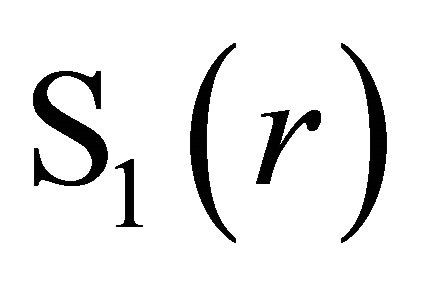 , and the amount of energy that Source 2 is able to deliver at Source 1, i.e.
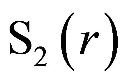 . This results in back reaction force
 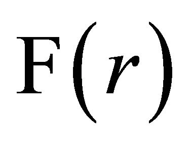 proportional to
 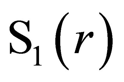 on Source 1 and
 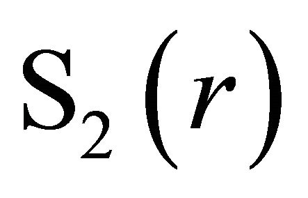 on Source 2, i.e. radiation reaction [4], and where γ is a constant. This creates mutual force of attraction
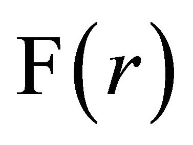 ,
,
 (2)
(2)
It is now assumed that each source is an MQ (mass quantum, defined below) and where its Poynting vector is 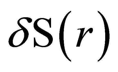 and where r denotes the distance from the source. E and H decrease linearly with the distance r implying that
 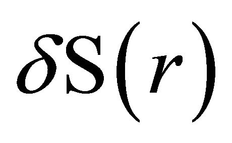 decreases with the square of the distance;
 . The mutual force of attraction
 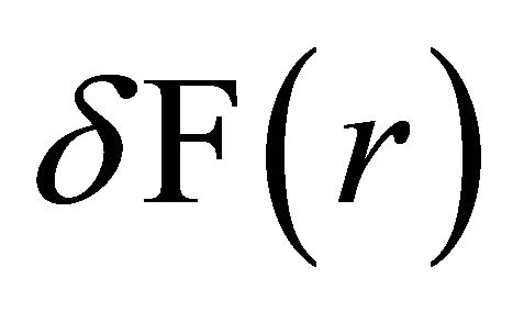 between two MQs at distance r is
 (3)
(3)
It is now assumed that one MQ acts on p collocated MQs, belonging to the set P of all MQs at Source 2, and where each force can be described by δF(r). These MQs are synchronized resulting in the force
 (4)
(4)
It is now assumed that n collocated MQs, belonging to the set N of all MQs at Source 1, act on p collocated MQs, belonging to the set P of all MQs at Source 2, resulting in the total force F(r),
 (5)
(5)
 is a constant described by the intrinsic characteristics of the MQ, and hence Equation (5) is simplified into
 (6)
(6)
where ξ is a constant.
In the present study Equation (6) is called the law of gravity between two clusters, at distance r containing n respectively p MQs. Note that the cluster can be few MQs, an atom, a mass or a planet.
The implication of Equation (3) is that an atomic MQ generates gravity quantum and consequently, the present theory applies to quantum gravity.
It is proposed that elementary entities or more precisely mass quanta MQs, in the atomic nucleus, contain intrinsic, combined electric and magnetic fields or electromagnetic dipoles. Every MQ creates resonance and receives Gravity Source plane TEM waves. This results in emitted TEM waves. Two MQs and their emitted TEM waves create mutual force of attraction δF(r). This is illustrated with gravity between the earth and the sun. The earth contains n mass quanta (MQs) creating a force 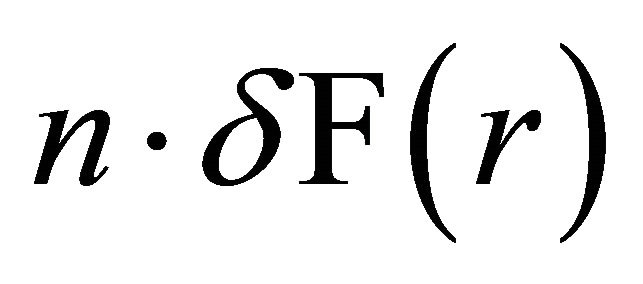 on every mass quanta (MQ) in the sun. The sun contains p mass quanta (MQs), thus the total force of attraction is
 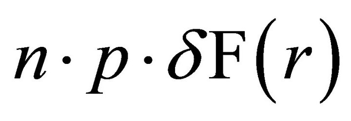 and that is equal to Equation (6). The earth’s mass m1 is proportional to the number of MQs on earth, i.e. m1 ~ n, and the sun’s mass m2 ~ p. Equation (6) is then approximately equal to the Newtonian geometric law of gravity
 (7)
(7)
Note that FG, G and the constant decreases with the distance to the Gravity Source.
3. Materials and Methods
All experiments were performed using one or many identical electronic devices called MQ. The MQ created resonance with plane TEM waves; it received and emitted plane TEM waves. Each MQ consisted of two neodymium magnets, with diameter 22 mm, spaced by a thin (0.05 mm) plastic foil. The south pole of one magnet attracted the north pole of the other. This created an internal magnetic field Bi. One magnet was connected to the positive pole of a voltage source U. The other magnet was connected to the negative pole, Figure 1. This created an internal electric field Ei, e.g. 106 V/m at U = 50 V. Bi and Ei were merged within the thin space between the magnets and could be described as electromagnetic dipoles. Measurements were performed with the neodymium magnets connected to a 9 V battery, forming a portable MQ, detached from external influence (e.g. AC, ground). This MQ was used in Experiments 5-10.
Experiments 1-4 and 11 were performed with the magnets connected to a low frequency signal generator with output voltage 0.5 mV RMS. Hence, the static electric
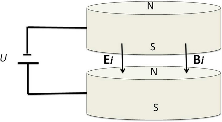
Figure 1. Generating TEM waves. Two neodymium magnets, with a diameter 22 mm, were spaced by a thin (0.05 mm) plastic foil with the south pole of one magnet attached to the north pole of the other. This created an internal magnetic field Bi. One magnet was connected to the positive pole of a voltage source U, and the other magnet to the negative pole. This created an internal electric field Ei, combined with Bi. This device, called MQ received and re-emitted plane TEM waves.
field was replaced by an alternating electric field. The MQ created resonance at the signal generator frequency; it received and re-emitted plane TEM waves having this frequency. This device, also called MQ, was used in order to measure the frequencies of plane TEM waves originating from the Gravity Source.
Measurements of plane TEM wave field vector amplitudes were made as described in [7]. That report describes in detail how the position and amplitude of electric and magnetic field vectors were measured using a charge meter. The charge meter is described in detail. Measurements in the present study were made almost identically to those described in [7]. In summary the charge meter contained a probe with charge density ρ. The probe was moved, with constant speed, through the TEM wave electric field vectors E. This resulted in an electric body force ρE on the probe charge density ρ. This current pulse was amplified and displayed. In this case E was field vectors, implying that divE was large and resulted in a distinct current pulse. This probe was also moved, with constant speed, through the TEM magnetic field vectors B, which resulted in a magnetic body force J × B on current J in the probe. In this case B was field vectors, implying that divB was large and resulted in a distinct current pulse. The measurement method had one important feature. The field vector’s physical length was proportional to its amplitude and in the present study between 0.1 - 10 m. It was easy to measure and determine the physical length of the field vectors since divE and divB were large. Hence, this was an accurate measure of the relative amplitude. Consequently, all results are presented as relative amplitude.
TEM waves propagating in two directions, from Source 1 to Source 2 and from Source 2 to Source 1, were measured in the following way. A permanent magnet with magnetic field BM (1 µT) was inserted within the TEM wave’s path, 1 m in front of Source 1. The propagating TEM wave consisted of electric E and magnetic B field vectors. The magnetic field BM created a force on the positive magnetic field vectors B+ and on the negative magnetic field vectors B−. According to [3] it made the TEM wave’s positive magnetic field vectors B+ divert the distance d1 to one side and the negative magnetic field vectors B− divert the distance d2 to the opposite side. TEM waves propagating in one direction (e.g. from Source 1 to Source 2) were influenced so that their field vectors were diverted in the horizontal plane, see Figure 2, the electric field vectors E where oriented in the horizontal plane and the magnetic field vectors B were oriented in the vertical plane. TEM waves propagating in the opposite direction (e.g. from Source 2 to Source 1) were influenced so that their field vectors were diverted in the vertical plane, see Figure 3. The electric field vectors E where oriented in the vertical plane and the magnetic field vectors B were oriented in the horizontal plane. This enabled measurement of the two directions separately. Consequently, TEM waves propagating in opposite directions between two sources were rotated 90 degrees relative to each other. The field vectors propagated in smooth bows distanced by the magnetic field BM.
Measurements were performed 50 km south of Stockholm, Sweden.
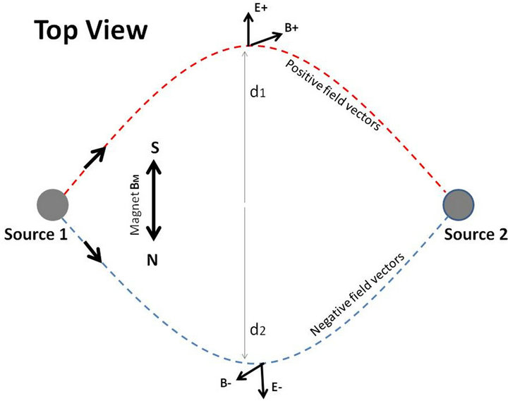
Figure 2. Measuring TEM waves propagating from Source 1. Two MQs, as described in Figure 1, Source 1 and Source 2, were positioned at 10 m distance. Source 1 was connected to a 9 V battery and Source 2 was also connected to a 9 V battery. This resulted in TEM waves propagating between the two sources. A permanent magnet BM was inserted within the flow of TEM waves, 1 m in front of Source 1. TEM waves propagating from Source 1 to Source 2 were diverted in the horizontal plane. This resulted in that positive field vectors E+ and B+ were diverted the distance d1 in the horizontal plane..The negative field vectors E− and B− were diverted the distance d2 to the opposite side in the horizontal plane. This enabled separate measurement of TEM waves propagating from Source 1 to Source 2, respectively from Source 2 to Source 1.
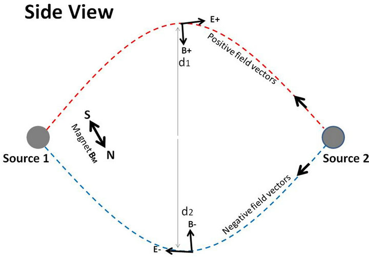
Figure 3. Measuring TEM waves propagating from Source 2. Two MQs, as described in Figure 1, Source 1 and Source 2, were positioned at 10 m distance. Source 1 was connected to a 9 V battery and Source 2 was also connected to a 9 V battery. This resulted in TEM waves propagating between the two sources. A permanent magnet BM was inserted within the flow of TEM waves, 1 m in front of Source 1. TEM waves propagating from Source 2 to Source 1 were diverted in the vertical plane. This resulted in that positive field vectors E+ and B+ were diverted the distance d1 in the vertical plane. The negative field vectors E− and B− were diverted the distance d2 to the opposite side in the vertical plane. This enabled separate measurement of TEM waves propagating from Source 2 to Source 1, respectively from Source 1 to Source 2.
Analysis: the experiments were performed blindly, randomly and repeated 3 times.
4. Results
Experiments 1-4 were made with the MQ connected to the signal generator. The purpose with these experiments was to verify plane TEM wave frequency and its origin. Initially the signal generator frequency was increased from 1 to 100 Hz in increments of 0.1 Hz. TEM wave amplitude close to the MQ was measured as a function of frequency. It was observed that the MQ received and emitted plane TEM waves from the object being measured at two distinct frequencies; 69.9 Hz and 91.9 Hz. The signal generator was adjusted to these two frequencies in Experiments 1-4. It was also observed that the MQ always received and emitted plane TEM waves from the earth (i.e. ground). Hence, the MQ did not generate TEM waves; its only function was to create resonance at the plane TEM wave frequency.
Experiment 1. The purpose with this experiment was to measure the frequency of TEM waves received from the Gravity Source. The method was to create resonance (i.e. low impedance) in an MQ, connected to a signal generator, and to measure the amplitude of transmitted and absorbed TEM waves as function of frequency. The purpose was also to measure the direction of TEM waves received from and transmitted to the Gravity Source. One MQ, connected to a signal generator, was positioned on a table and this was called Source 1. The signal generator frequency was 69.9 Hz and then changed to 91.9 Hz. The generator frequency was carefully adjusted to maximum TEM wave field vector amplitude. 1‰ deviation in frequency resulted in approximately 50% change in TEM wave field vector amplitude, which illustrates the demand for accuracy. The MQ was activated at the frequency 69.9 Hz for 48 hours in order for the experiment to stabilize. It was observed that the field vector amplitude increased approximately 10 times during 48 hours. It also continued to increase after 48 hours by approximately 10% daily. It produced plane TEM1 waves propagating from Source 1 towards north (earth’s rotational axis). It followed a diurnal, counter-clockwise circle with approximately 20 degrees cone angel. Its peak altitude was approximately 75 degrees and occurred at noon (in Sweden) and the direction was towards the geographical north +/− 5 degrees. Plane TEM2 waves propagated from a source in the universe towards Source 1, aligned along and merged with TEM1. It was possible to measure TEM1 and TEM2 separately by inserting a magnet, with magnetic field BM 1 m in front of Source 1, as explained in Figure 2 and in Figure 3. The procedure is also explained in Experiment 10. Measurements displayed electric field vectors E+ and E− and magnetic field vectors B+ and B− perpendicular to the direction from Source 1 to Source 2 and from Source 2 to Source 1. In each direction the field vectors E+ and B+ respectively E− and B− were perpendicular, i.e. separated 90 degrees as in any plane TEM wave, e.g. radio wave [3]. E and B in one direction were rotated 90 degrees relative to E and B in the opposite direction, as described in Figures 2 and 3. In each direction the amplitudes were identical, i.e. E+ = E− and B+ = B; however, they varied between the two directions. Positioning an electric or magnetic field close to the field vectors changed their positions, confirming their nature and polarity. The method is described in [7]. The experiment was repeated, using generator frequency 91.9 Hz, displaying similar results. It is proposed that Source 2 was the Gravity Source generating plane TEM waves with the frequency 69.9 Hz and 91.9 Hz. The experiment displayed that the MQ, Source 1, received TEM2 waves from the Gravity Source and that it produced TEM1 waves which propagated in the direction towards the Gravity Source.
Experiment 2. The purpose with this experiment was to measure the frequency of TEM waves received from and transmitted to the sun. The method was to create resonance (i.e. low impedance) in an MQ, connected to a signal generator, and to measure the amplitude of transmitted and absorbed TEM waves as function of frequency. The purpose was also to measure the direction of TEM waves received from and transmitted to the sun. Experiment 1 was repeated; however, in this case TEM1 and TEM2 waves to and from the sun were measured at 69.9 Hz and then at 91.9 Hz. Measurements displayed results similar to Experiment 1, and where the only differences were the direction of the TEM waves and their amplitudes. TEM1 and TEM2 waves were always directed to and from the sun during daytime. The amplitude of plane TEM waves to/from the sun were less than 5% of the plane TEM waves to/from the Gravity Source, indicating the huge influence of the Gravity Source.
Experiment 3. The purpose with this experiment was to measure the frequency of TEM waves received from and transmitted to the moon. The method was to create resonance (i.e. low impedance) in an MQ, connected to a signal generator, and to measure the amplitude of transmitted and absorbed TEM waves as function of frequency. The purpose was also to measure the direction of TEM waves received from and transmitted to the moon. Experiment 1 was repeated; however, in this case plane TEM1 and TEM2 waves to and from the moon were measured at 69.9 Hz and then at 91.9 Hz. Measurements displayed results similar to Experiments 1 and 2, and where the only differences were the direction of the TEM waves and their amplitudes.
Experiment 4. The purpose with this experiment was to measure the frequency of TEM waves received from and transmitted to a mass. The method was to create resonance (i.e. low impedance) in an MQ, connected to a signal generator, and to measure the amplitude of transmitted and absorbed TEM waves as function of frequency. The purpose was also to measure the direction of TEM waves received from and transmitted to a mass. Experiment 1 was repeated; however, in this case plane TEM1 and TEM2 waves to and from a nearby object (e.g. 10 kg iron) were measured at 69.9 Hz and then at 91.9 Hz. Measurements displayed results similar to experiments 1, 2 and 3. The amplitude of E+ = E− and B+ = B− were proportional to the object’s mass and inverse proportional to the objects distance r to the MQ, Source 1.
Experiments 5-7 aimed at verifying the theoretical model, presented in Section 2. One MQ or many collocated MQs were positioned at Source 1. Source 2 was located at the distance r = 10 m and one or many MQs were positioned at Source 2. All MQs were connected to a 9 V battery each. It produced plane TEM1 waves propagating from Source 1 to Source 2 and plane TEM2 waves propagating from Source 2 to Source 1. Measurements displayed electric field vectors E+ and E− and magnetic field vectors B+ and B− perpendicular to the direction from Source 1 to Source 2 and from Source 2 to Source 1. In each direction the field vectors E+ and B+ respectively E− and B− were perpendicular, i.e. separated 90 degrees as in any plane TEM wave, e.g. radio wave [3]. In each direction the amplitudes were identical, i.e. E+ = E− and B+ = B−. It was also observed that Source 1 and Source 2 received and emitted plane TEM waves from the Gravity Source and from the earth (i.e. ground). Hence, the energy in TEM1 and TEM2 originated from these sources. Consequently, the MQs did not generate TEM waves; their only function was to create resonance with low frequency plane TEM waves and to re-emit them.
Experiment 5. The purpose of this experiment was to validate the theoretical model Equations (2) and (6); .
. 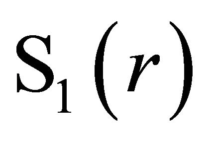 and
and 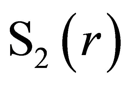 were measured as a function of n and p. The purpose was also to simulate variation of n by varying the voltage U on one MQ. One MQ was positioned at Source 1 and one MQ at Source 2. The amplitude of the field vectors E+ were measured in both directions (i.e. TEM1 from Source 1 to Source 2 and TEM2 from Source 2 to Source 1).
Then the number n of MQs at Source 1 was increased to 4 in steps of 1. Subsequently the number p of MQs at Source 2 was increased to 4 in steps of 1. Measurements displayed that the amplitude of the electric and magnetic field vectors E+, E−, B+ and B− were proportional to n·p in both directions. Subsequently the MQ at Source 1 was connected to a variable voltage source and the voltage U on Source 1 was varied from 0 to 40 V in steps of 5 V. Measurements displayed that the amplitude of the electric and magnetic field vectors E+, E−, B+ and B− were proportional to U in both directions, see Figure 4.
Experiment 6. The purpose of this experiment was to
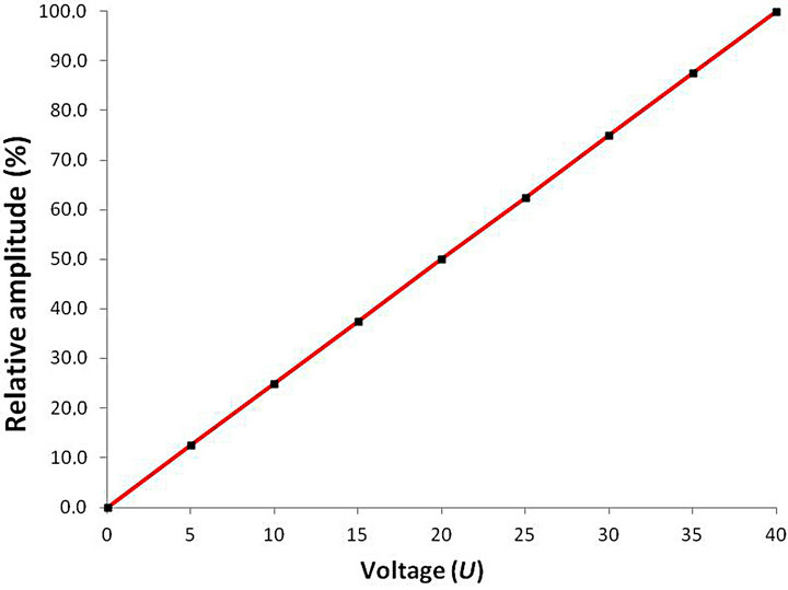
Figure 4. Field vector amplitude as function of voltage on one MQ. Two MQs, as described in Figure 1, Source 1 and Source 2, were positioned at 10 m distance. Source 2 was connected to a 9 V battery. The voltage U on Source 1 was varied from 0 - 40 V in steps of 5 V. The amplitude of the plane TEM1 and TEM2 wave’s electric and magnetic field vectors (E+, B+, E− and B−) was measured as a function of the voltage U. The amplitudes of all four field vectors were proportional to U and E+ = E− and B+ = B− in both directions. E+ amplitude in TEM1 as function of U is displayed in Figure 4.
validate the theoretical model Equations (2) and (6); .
. 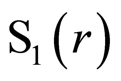 and
and 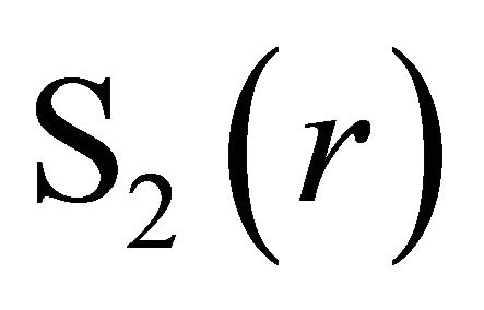 were measured as a function of r. One MQ was positioned at Source 1 and one MQ at Source 2. The distance r between Source 1 and Source 2 was varied, starting with r = 1 m, then increased to 10 m in steps of 1 m. The amplitude of the field vectors E+, E−, B+ and B− were measured in both directions as a function of the distance r. Measurements displayed that the amplitudes of the electric and magnetic field vectors E+, E−, B+ and B− were inverse proportional to the distance r in both directions, see Figure 5.
Experiment 7. The purpose of this experiment was to verify that there was a transfer of energy from S1(r) to S2(r) vice versa according to Equation (2). One MQ was positioned at Source 1 and one MQ at Source 2 and the distance between them was 10 m. The amplitude of the field vectors E+, E−, B+ and B− were measured at different distances from Source 1 along the straight direction from Source 1 to Source 2, and measured in both directions. Measurements displayed that the amplitude of the sum of electric and magnetic field vectors E+, E−, B+ and B− from both directions (i.e. TEM1 + TEM2) were constant at every position between Source 1 and Source 2. E+, B+, E− and B− were spaced 90 degrees in both directions, as in any plane TEM wave.
In the following Experiments 8 and 9 an MQ, connected to a 9 V battery, was positioned at Source 1. Source 2 was a mass in Experiment 8 and the sun in Experiment 9.
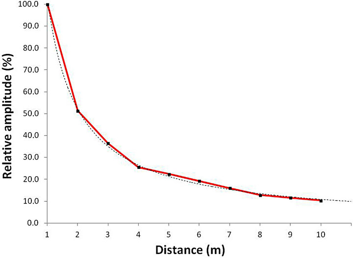
Figure 5. Field vector amplitude as a function of distance. Two MQs, described in Figure 1, were positioned at the distance r, which was initially 1 m and then increased to 10 m in steps of 1 m. The amplitude of TEM1 and TEM2 wave’s electric and magnetic field vectors (E+, B+, E− and B−) was measured as a function of the distance r in both directions. The amplitudes of all field vectors were proportional to1/r and E+ = E− and B+ = B− in both directions. E+ amplitude in TEM1 as function of r is displayed in Figure 5. The dotted line represents the theoretical decline 1/r.
Experiment 8. The purpose of this experiment was to validate the theoretical model Equation (2), Equations (6) and (7); F(r) = γ·S1(r)·S2(r) = ξ·n·p/r2 ≈ FNewton = G·m1·m2/r2. S1(r) and S2(r) were measured as a function of the mass m2. A mass, m2, (Source 2) which consisted of iron was positioned 5 m from the MQ at Source 1. The mass m2 was increased from 0 to 10 kg in increments of 1 kg. Measurements displayed plane TEM1 waves propagating from Source 1 to the mass m2 and plane TEM2 waves propagating from the mass m2 to Source 1. The amplitude of the field vectors E+, E−, B+ and B− were measured, in both directions, as a function of the mass m2. Measurements displayed that the amplitude of the electric and magnetic field vectors E+, E−, B+ and B− were proportional to the mass m2 in both directions, see Figure 6. It was also observed that the mass m2 received and emitted plane TEM waves to and from the Gravity Source and the earth (i.e. ground).
Experiment 9. The purpose with this experiment was to show that Equation (2),  , was only valid at steady state and to demonstrate how this steady state was achieved. Measurements were performed outside Stockholm, Sweden during the daytime. Source 1, consisting of one MQ, was positioned on a table. Measurement started by activating Source 1 (i.e. the MQ was connected to a 9 V battery). Measurements were performed 2 m in front of Source 1 and roughly in the direction of the sun. Measurements displayed plane TEM1 waves propagating from Source 1 in direction towards the sun (Source 2) and plane TEM2 waves propagating in the opposite direction. The amplitude of the field vectors
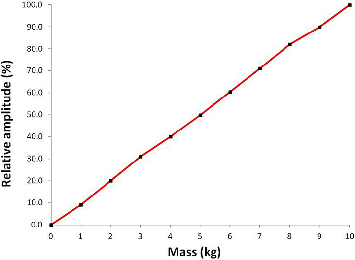
Figure 6. Field vector amplitude as a function of mass. One MQ (Source 1) was positioned 5 m from a mass which consisted of iron (Source 2). The mass was changed from 0 - 10 kg in steps of 1 kg. The amplitude of TEM1 and TEM2 wave’s electric and magnetic field vectors (E+, B+, E− and B−) was measured as a function of mass m. The amplitudes of all four field vectors were proportional to m in both directions and E+ = E− and B+ = B−. E+ amplitude in TEM1 as function of the mass m is displayed in Figure 6.
E+, E−, B+ and B− were measured as a function of time (both TEM1 and TEM2). Measurements displayed that the amplitude of TEM1 electric and magnetic field vectors E+, E−, B+ and B− increased approximately six times the initial amplitude within 16 minutes. Then they remained stable displaying no change in amplitude, see Figure 7.
Measurement was also performed on plane TEM waves to and from the Gravity Source (after 48 hours). TEM wave amplitude of the Gravity Source was more than 20 times larger than the TEM wave amplitude towards the sun, indicating its large influence. Note that TEM wave amplitude from the Gravity Source continued to increase after 48 hours by approximately 10% daily. Hence, it is reasonable to assume that the influence from the Gravity Source was very large.
Experiment 10. The purpose of this experiment was to introduce a method which facilitated separate measurement of TEM waves travelling in opposite direction, as described in Figures 2 and 3. Experiments 1-9 were enhanced in the following way; a static magnetic field BM (i.e. a 1 µT magnet) was inserted at the centre of the plane TEM1 and TEM2 waves, 1 m from Source 1, see Figures 2 and 3. It was observed that in Experiment 1,
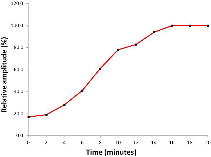
Figure 7. Field vector amplitude towards the sun as a function of time. One MQ, Source 1, was positioned on a table. The sun constituted Source 2. Measurements displayed plane TEM1 waves propagating from Source 1 in direction towards the sun and plane TEM2 waves propagating in direction from the sun to the MQ, Source 1. The amplitude of the plane TEM1 and TEM2 waves electric and magnetic field vectors (E+, B+, E− and B−) was measured as a function of time. The amplitudes of field vectors were E+ = E− and B+ = B− at all times. After 16 minutes the amplitude was constant during an 8 hour measured period. The direction of plane TEM1 waves and plane TEM2 waves followed the position of the sun. After 16 minutes the length of TEM1 field vectors were approximately 2 m at U = 9 V, indicating that the electric and magnetic field strength was significant and thus the field divergence divE was significant and easy to measure.
TEM1 was diverted much further than TEM2, which provided a way to measure the plane TEM waves to and from the Gravity Source separately and to make a relative comparison between TEM1 and TEM2 amplitudes. It was also observed that in Experiment 9, TEM1 was diverted much further than TEM2, during the initial 8 minutes. It facilitated a way to measure the plane TEM waves to and from the sun separately and to make a relative comparison between TEM1 and TEM2 amplitudes.
Experiment 11. The purpose with this experiment was to measure extremely low frequency TEM waves received from the Gravity Source. The method was to create resonance (i.e. low impedance) in an MQ, connected to a signal generator, and to measure the amplitude of the absorbed TEM wave. One MQ, connected to a signal generator, was positioned on a table and this was called Source 1. The signal generator frequency was changed from 0.1 Hz to 1 Hz in steps of 0.01 Hz. The generator voltage was 0.5 mV RMS. It was observed that the MQ created resonance at 0.74 Hz and received plane TEM2 waves from the direction of the Gravity Source. It was also observed that the MQ radiated 0.74 Hz plane TEM1 waves to every type of matter, Source 2, in its vicinity. The amplitude of TEM1 was proportional to the mass of Source 2. Furthermore, the amplitude of TEM1, at Source 1, decreased linearly with the distance to Source 2. It was also observed that the amplitude of TEM1 along the straight line between Source 1 and Source 2 decreased linearly with the distance from Source 1. It was not possible to observe any TEM2 waves propagating from matter, Source 2, to the MQ, Source 1. It was concluded that the Gravity Source radiated plane TEM waves at 0.74 Hz and that this energy was absorbed by matter and probably re-emitted uniformly. The amplitude of the 0.74 Hz TEM wave, absorbed by matter, was significantly higher than the amplitude of 69.9 Hz and 91.9 Hz TEM waves propagating to the same matter (approximately 10 times larger).
It was observed in Experiments 1-11 that vertically propagating plane TEM waves (e.g. to/from the earth) resulted in that magnetic field vectors were oriented north to south caused by influence from the geomagnetic field. Otherwise the magnetic field vectors were oriented vertically, also the result of influence from the geomagnetic field. Consequently, the plane TEM waves were polarized which explains the efficiency of the measurement method used in Experiments 1-11.
5. Discussion
Experiments 2 and 9 displayed that gravity between the electronic device MQ (Figure 1) and the Gravity Source was much larger than gravity between the electronic device MQ and the sun. From Section 4 and 5 follows that gravity between the electronic device MQ and the Gravity Source was significant. It is proposed that the MQ within the atom (atomic MQ) behaves similar to the electronic device MQ. Consequently, the atomic MQ was exposed to two different gravity components, gravity between the atomic MQ and all other atomic MQs in the universe and gravity between the atomic MQ and the Gravity Source. It is proposed that the former is called gravitational gravity and the latter is called inertial gravity. The inertial gravity results in that the universe rotates (spirals) around the Gravity Source. Exposing the MQ to force accelerates the MQ relative to all other MQs and the Gravity Source. It can be illustrated with an MQ travelling through space, far away from planets and stars. It is primarily influenced by TEM waves from and to the Gravity Source. Its reference frame is the Gravity Source or more precisely TEM energy at MQ proximity. Its energy state relative to its reference frame (i.e. TEM energy generated by the Gravity Source) is changed when the MQ is accelerated and hence . a is the acceleration created by the quantified force δF on the inertial mass quantum
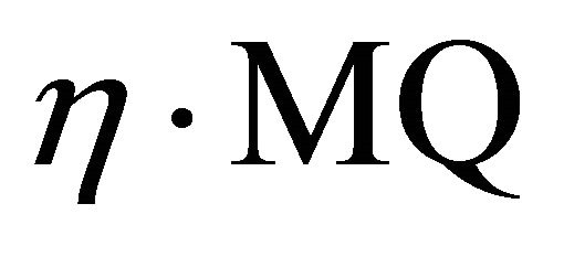 . A mass on earth experiences two reference frames. The first is the earth and its gravity and the second is the Gravity Source and its gravity. Hence, this mass m can be described as inertial mass,
  and gravitational mass,
  according to Equations (6) and (7). η and ß are constants. This explains why, according to classical mechanics, the gravitational mass is proportional to the inertial mass. It is proposed that mass does not exist. Mass is only the observation of electromagnetic energy (i.e. TEM waves originating from the Gravity Source) operating on electric and magnetic fields, i.e.
 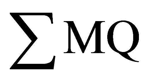 in atoms In that case Einstein’s mass-energy equivalence may relate to the MQ,
  , where ζ is a constant.
The atom is in traditional physics described by its particles, quarks, gluon, graviton, baryon, proton, electron etc. and by its forces, the strong interaction, the weak interaction, electromagnetism and gravity, described in the Standard Model [8,9]. The present paper describes the atomic MQ (mass quantum) as an atomic entity creating gravity and inertia. The MQ consists of a static electric field in parallel with a magnetic field.
In its simplest form the MQ may consist of only two charges, a positive and a negative elementary charge forming an electric dipole. This dipole absorbs plane TEM waves from the Gravity Source with the frequency 0.74 Hz and this induces an electric and magnetic field with the frequency 0.74 Hz. Hence, this dipole consists of a static electric field and an almost static magnetic field. Consequently, the dipole can be regarded as an electromagnetic dipole which also creates resonance with plane TEM waves (gravity waves) at 69.9 Hz and 91.9 Hz. This dipole is called MQ in the present paper and it is the atom’s elementary entity and also the atom’s mass quantum.
The dipole (MQ) has electric and magnetic fields, electric and magnetic dipole moments, it produces gravity (mass) and it produces inertia (inertial mass). The force on one dipole (MQ) in the atom from all other dipoles (MQs) in the atom is entirely electromagnetic, i.e. caused by electromagnetic fields. The fields operating on the dipole consist of the vector sum of electric fields (Coulomb field) from all dipole’s charges, the vector sum of electric dipole moments from all dipoles, the vector sum of induced electromagnetic fields (at 0.74 Hz) from all dipoles and the vector sum of induced electromagnetic dipole moments (at 0.74 Hz) from all dipoles.
The (induced) magnetic force (at 0.74 Hz) dominates within the atom’s nucleus. It is proposed that this magnetic force represents what is commonly called gluon and the strong interaction. The electric force (Coulomb force) is strong within a dipole and between adjacent dipoles. Hence, the electric force can contribute to the strong interaction. However, within the atom’s nucleus the electric force is normally smaller than the magnetic force. The force from electric and magnetic dipole moments is probably small. It is proposed that the electric force and the dipole moments normally represent what is commonly called the weak interaction and electromagnetism. The conclusion is that the atom can be described by configurations of MQs (dipoles) and elementary charges and by electromagnetic fields creating two forces; the magnetic force and the electric force. In addition the atomic MQs create resonance with gravity waves (TEM waves) and re-emit them. The flow of gravity waves between two MQs creates mutual force of attraction, i.e. gravity. Thus gravity is an electromagnetic force.
Positioning two MQs (dipoles) side-by-side; however, in opposite directions, results in strong magnetic and electric forces which fuses the MQs. MQs can be added forming a matrix. Such configuration can be described as a quark and various configurations can be described as various types of quarks.
Amalgamated quarks result in baryons, e.g. neutron. A proton is created when a positive elementary charge is added to one MQ in a neutron. An electron is created when a negative elementary charge is added to one MQ in a small configuration of MQs (e.g. a dipole with one positive charge and two negative charges). The sum of these configurations of MQs is the atom.
Consequently, the atom may consist of only positive and negative elementary charges configured into MQ, electron, quark, neutron, proton etc. Hence, the universe may consist of only positive and negative elementary charges and different configurations of these charges. All forces in the universe are electromagnetic forces induced by the position and motion (i.e. velocity and acceleration)
of these elementary charges and their configurations, according to the laws of electromagnetism. The Gravity Source may consist of rotating charges and its generated TEM waves are the main provider and carrier [6] of energy within the universe. This model enables description of phenomena within the universe (e.g. dark energy, dark matter, expanding space, black hole, gravitational lensing and redshift) based on the laws of electromagnetism.
Equation (2)  describes the mutual force of attraction when the positions of the two sources are static relative to each other. When one source rotates relative to the other a force perpendicular to r is introduced and this force and the labor performed are minimized when the source’s rotational axis is directed towards the other source. Experiment 1 displayed that the direction towards the Gravity Source was to the north, aligned to the earth’s rotational axis; however, with a small misalignment. It is known that the Milky Way galaxy and its Galactic Centre contains the astronomical radio source Sagittarius A*. It has also been proposed that the Galactic Centre contains a super massive black hole. The earth’s rotational axis is oriented towards the Galactic Centre; however, with a small misalignment [10,11]. Data from the WMAP mission display that distribution of energy in universe is anisotropic and may be aligned relative to the earth’s rotational axis [12]. This anisotropic distribution of energy has recently (21 March 2013) been confirmed by data released from the Planck mission. Perhaps the earth’s rotational axis and the Milky Way are oriented towards a concentration of mass in the universe and this concentration of mass is the Gravity Source. The universe expands and perhaps the Milky Way and the earth moves in direction from the Gravity Source, i.e. in the direction of the earth’s geographical south? Compiling the present findings with known galaxy filaments may provide improved understanding of the universe.
It is proposed that there are three quanta. The positive and the negative elementary charges are the Charge Quantum. The atomic dipole is the Mass Quantum. The gravity wave and photon is the carrier of energy. The photon consists of electromagnetic energy superpositioned on gravity waves [6]. The gravity wave is the Energy Quantum. All three can be included in (modified) quantum physics. The fundament of modified quantum physics may comprise Charge Quantum, Energy Quantum and Mass Quantum operating on the laws of electromagnetism.
6. Conclusions
The study proposes that gravity is created by plane TEM (transverse electromagnetic) waves, which is the solution to Maxwell’s equations  and
and  [3]. The gravitational force or mutual force of attraction between two synchronized plane TEM waves travelling in opposite direction is proportional to the scalar product of their Poynting vectors [4] according to Equation (2).
It is proposed that a gravitational singularity called the Gravity Source emitted plane TEM waves to elementary entities, or more precisely, to mass quanta, MQs, within the atom’s nucleus. It is proposed that the MQ contained intrinsic, merged electric and magnetic fields or electromagnetic dipoles or one electric dipole. These almost static merged fields created resonance with the plane TEM wave’s almost static field vectors. The received plane TEM waves were re-emitted as plane TEM waves and distributed to, in principle, every MQ in the universe and where the amplitude decreased linearly with the distance to the MQ. The content of these plane TEM waves remained unchanged. Simultaneously every MQ in the universe received plane TEM waves from, in principle, every other MQ in the universe. The plane TEM wave amplitude was inverse proportional to the distance between the MQs. Energy emitted by the Gravity Source was partly re-emitted to the Gravity Source. Hence, every MQ was also exposed to gravity from the Gravity Source.
The mutual force of attraction between two MQs is described by Equation (3). The mutual force of attraction between two masses (i.e. the sum of contributions from many MQs) is described by Equation (6), which is approximately equal to the Newtonian geometric law of gravity according to Equation (7).
The plane TEM wave frequency was measured in Experiments 1-4 using a device, MQ, which created resonance at a predetermined frequency; it received and re-emitted plane TEM waves at one particular frequency. It consisted of an internal alternating electric field Ei with frequency 0.74 Hz, 69.9 Hz or 91.9 Hz, merged with an internal static magnetic field Bi.
Experiment 1. This experiment confirmed the existence of the Gravity Source generating plane TEM waves with the frequency 69.9 Hz and 91.9 Hz. The direction towards the Gravity Source was to the north and followed a diurnal, counter-clockwise circle with approximately 20 degrees cone angle. It was assumed that the diurnal change of direction was caused by the rotation of the earth and where the earth’s axis was misaligned 10 degrees relative to the direction towards the Gravity Source.
Experiment 2. This experiment displayed that plane TEM wave’s amplitude to/from the Gravity Source was at least twenty times the plane TEM wave’s amplitude to/from the sun, confirming its large influence.
Experiments 2-4. These experiments confirmed that the sun, the moon, the earth and an object (e.g. iron) positioned in close proximity to the MQ, produced and received synchronized and mutually coupled plane TEM waves with frequency 69.9 Hz and 91.9 Hz. It indicated that these objects produced 69.9 Hz and 91.9 Hz plane TEM waves and that these plane TEM waves were synchronized to the Gravity Source’s plane TEM waves.
Experiment 5. The purpose of this experiment was to validate the theoretical model Equation (2) and Equation (6); .
. 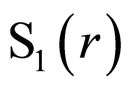 and
and 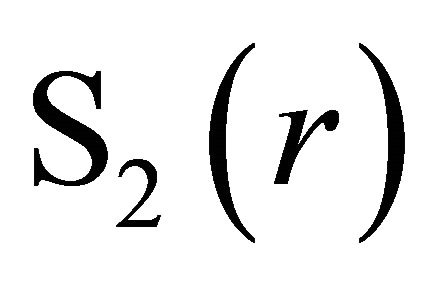 were measured as a function of n and p. n respectively p MQs were positioned at a distance r. Results displayed that E+, B+, E− and B− amplitudes were proportional to n·p confirming Equations (2) and (6) and also Equations (3)-(5). This was simulated by varying the voltage U on Source 1, resulting in proportional change in field vector amplitude and within the measurement accuracy as displayed in Figure 4.
Experiment 6. The purpose of this experiment was to validate the theoretical model Equation (2) and Equation (6); .
.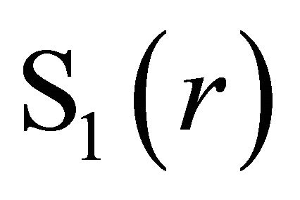 and
and 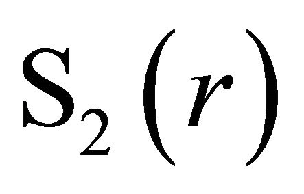 were measured as a function of r. In this experiment the distance r between MQs was varied, displaying that field vector amplitudes E+, B+, E− and B− were proportional to 1/r confirming Equations (2)-(6). Measured data was in good agreement with the theoretical decline 1/r, displayed in Figure 5. (Note that field vectors decreased with 1/r while energy decreased as 1/r2).
Experiment 7. Plane TEM waves propagating between two MQs displayed that the sum of TEM1 and TEM2 field vector amplitudes were constant all the way from one MQ to the other MQ. It indicated the mutual coupling between synchronized plane TEM1 and TEM2 waves propagating in opposite direction. It is proposed that there was a transfer of energy between the two TEM waves. This transfer of energy and the back reaction force that the plane TEM waves created on its source created mutual force of attraction or gravity according to Equation (2). Consequently, Experiment 7 supports the theoretical model.
Experiment 8. The purpose of this experiment was to validate the theoretical model Equation (2), Equation (6) and Equation (7); F(r) = γ·S1(r)·S2(r) = ξ·n·p/r2 ≈ FNewton =G·m1·m2/r2. S1(r) and S2(r) were measured as a function of the mass m2.This experiment proved that an object (mass) produced gravity proportional to its mass m, confirming Equations (6) and (7). This experiment showed that a mass produced plane TEM waves identical the Gravity Source, the sun, the moon and also the electronic device used in Experiments 1-7. This indicates that the mass, the sun and the moon contained similar type of mechanism of intrinsic nature and similar to the function of the electronic device called MQ. It is proposed that the mass, the sun and the moon contained an elementary entity or mass quantum which created resonance and re-emitted gravity TEM waves originating from the Gravity Source. It is proposed that the mass quantum consisted of an intrinsic electric field or dipole merged with a magnetic field or dipole.
Experiment 9. The purpose with this experiment was to show that Equation (2),  , was only valid at steady state and to demonstrate how this steady state was achieved. It took approximately 16 minutes to stabilize the TEM1 waves propagating from Source 1 (the MQ) to Source 2 (the sun) and the TEM2 waves propagating from Source 2 to Source 1. The field vectors reached their maximum amplitude after approximately 16 minutes. The round trip to the sun was 16.6 minutes at the speed of light. It can be explained as follows. The MQ at Source 1 was switched on at time t = 0 minutes. After 8.3 minutes (t = 8.3) TEM1 waves reached the sun creating the force
  at the sun. Then it took another 8.3 minutes (t = 16.6) before the influenced TEM2 waves reached Source 1. The two synchronized TEM1 and TEM2 waves created mutual force of attraction between Source 1 and Source 2, and full gravity (at t = 16.6). The experiment confirmed the mutual exchange of energy between the two sources according to Equation (2) and also that plane TEM waves (off course) propagated with the speed of light.
Experiment 10 displayed that it was possible to separate TEM1 waves from TEM2 waves and that it was possible to measure the two directions separately.
Experiment 11 displayed that investigated matter contained some type of mechanism that absorbed plane TEM waves at 0.74 Hz, originating from the Gravity Source. Hence, TEM waves at 0.74 Hz were absorbed by matter and its atoms. Consequently, the absorbed TEM wave energy must induce electric and magnetic fields with the frequency 0.74 Hz within atoms.
The conclusion is that the universe contained a gravitational singularity called the Gravity Source. It generated plane TEM waves with the frequency 69.9 Hz and 91.9 Hz. Atomic mass quanta, MQ, consisting of intrinsic, merged static electric and magnetic fields or dipoles created resonance with these plane TEM waves. They were then re-emitted to other atomic MQs as plane TEM waves with the frequency 69.9 Hz and 91.9 Hz. Atomic MQs in the universe were synchronized to the Gravity Source which resulted in that received and emitted plane TEM waves were synchronized, causing exchange of energy and mutual force of attraction, which is called gravity. The atom consisted of many MQs. This resulted in an equation called the electromagnetic law of gravity, Equation (6). It was compared with the Newtonian geometric law of gravity, Equation (7). In addition the Gravity Source radiated plane TEM waves at 0.74 Hz, which was absorbed by matter and the absorbed plane TEM wave amplitude was linear to the mass, indicating an intrinsic atomic mechanism.
The following offers a possible explanation to the origin of the Gravity Source. It is proposed that the Gravity Source consisted of a kernel of charge rotating at three speeds (i.e. T = 1/0.74 s, T = 1/69.9 s and T = 1/91.9 s), constituting a gigantic electromagnetic generator. It emitted photons and their plane TEM waves with frequency 0.74 Hz, 69.9 Hz and 91.9 Hz.
Experiments 1-11 can also be summarized as follows. Gravity consisted of extremely low frequency plane TEM waves. Using state of the art measurement technique would require unrealistically long antennas. The method was to create plane TEM wave spatial divergence, which was created with the electronic device called MQ and polarization created by the geomagnetic field. The plane TEM wave spatial divergence created TEM wave field vector divergences divE and divB which were measured with a charge meter. This innovative measurement technique enabled unbundling of gravity.
It is proposed that the present study unifies gravity, described by Equation (6), with electromagnetic theory and quantum physics. Hence, this electromagnetic theory of gravity supplements Newtonian geometric theory of gravity, relativistic metric theory of gravity, Newton’s second law of motion and Einstein’s mass-energy equivalence.
REFERENCES
- J. H. Schwarz, “From Superstrings to M Theory,” Physics Reports, Vol. 315, 1999, pp. 107-121. doi:10.1016/S0370-1573(99)00016-2
- O. Aharony and E. Silverstein. “Supercritical stability, transitions, and (pseudo)tachyons,” Physical Review D, Vol. 75, No. 4, 2007. doi:10.1103/PhysRevD.75.046003
- B. I. Bleaney and B. Bleaney, “Electricity and Magnetism,” Oxford University Press, London, 1965.
- D. B. Melrose and R. C. McPhedran, “Electromagnetic Processes in Dispersive Media,” Cambridge University Press, Cambridge, 1991.
- S. S. Afshar, E. Flores, K. F. McDonald and E. Knoesel, “Paradox in Wave-Particle Duality,” Foundations of Physics, Vol. 37, No. 2, 2007, pp. 295-305. doi:10.1007/s10701-006-9102-8
- H. W. Giertz, “Photons Are EM Energy Superpositioned on TEM Waves,” Open Journal of Microphysics, in press, 2013.
- H. W. Giertz, “Extremely Low Frequency Electromagnetic Energy in the Air,” Journal of Atmospheric and Solar-Terrestrial Physics, Vol. 72, No. 9-10, 2010, pp. 767- 773. doi:10.1016/j.jastp.2010.03.022
- J. F. Donoghue, E. Golowich and B. R. Holstein, “Dynamics of the Standard Model,” Cambridge University Press, Cambridge, 1994.
- S. Braibant, G. Giacomelli and M. Spurio, “Particles and Fundamental Interactions: An Introduction to Particle Physics,” Springer Verlag, Heidelberg, 2009.
- D. C. Backer and R. A. Sramek, “Proper Motion of the Compact, Nonthermal Radio Source in the Galactic Center, Sagittarius A*,” The Astrophysical Journal, Vol. 524 No. 2, 1999, pp. 805-815. doi:10.1086/307857
- S. S. Doeleman, et al., “Event-Horizon-Scale Structure in the Supermassive Black Hole Candidate at the Galactic Centre,” Nature, Vol. 455, No. 7209, 2008, pp. 78-80. doi:10.1038/nature07245
- G. Hinshaw, et al., “Three-Year Wilkinson Microwave Anisotropy Probe (WMAP) Observations: Temperature Analysis,” The Astrophysical Journal Supplement Series, Vol. 170, No. 2, 2007, pp. 288-334. doi:10.1086/513698

