Advances in Internet of Things
Vol.3 No.2A(2013), Article ID:33327,11 pages DOI:10.4236/ait.2013.32A007
A Wireless Body Sensor Platform to Detect Progressive Deterioration in Musculoskeletal Systems
School of Computing and Mathematical Sciences, Liverpool John Moores University, Liverpool, UK
Email: P.Hanley@ljmu.ac.uk, P.Fergus@ljmu.ac.uk, F.Bouhafs@ljmu.ac.uk
Copyright © 2013 Paul Hanley et al. This is an open access article distributed under the Creative Commons Attribution License, which permits unrestricted use, distribution, and reproduction in any medium, provided the original work is properly cited.
Received February 6, 2013; revised March 7, 2013; accepted March 15, 2013
Keywords: Sensors; Sensor Networks; Networked Medical Devices; Networked Appliances; Home Networking; Real-Time Monitoring; Preventative Technologies; High Precision Measurement
ABSTRACT
Recent developments in technology have helped to reduce the physical size and weight of devices and opened up new opportunities for their application in delivering unobtrusive healthcare services. In particular, kinetic and kinematic systems, that use sensors attached to the body, are currently being used to measure and understand many different aspects of human gait and behaviour. This has been particularly useful in treating stroke patients, rehabilitation, and understanding sedentary behaviour. Nonetheless, many of these systems are only capable of providing information about rudimentary movement rather than data on the mechanics of motion itself (tendons, ligaments and so on). Therefore, the information required by healthcare professionals to treat diseases like progressive deterioration of the musculoskeletal system, i.e. arthritis, cannot be determined. This paper discusses some of the technologies currently used to assess movement and posits a novel approach based on strain gauge technology to measure the constituent parts of a joint and its movement. In this way, the mechanics of motion can be studied and used to help detect and treat musculoskeletal diseases. A case study is presented to demonstrate the applicability of our approach.
1. Introduction
The home environment, with its range of digital services, provides an opportunity to integrate and use healthcare services beyond current practice. This has the potential to provide huge benefits to different user groups, i.e. consumer electronics manufacturers, healthcare facilities and more importantly people. Yet, the market is still relatively unexplored and as such, there is a unique opportunity to utilize technology in novel ways and provide care in the community. There are good reasons for doing this. Perhaps most obvious is the fact that conditions are more often than not only detected when the effects of diseases are irreversible. For example, debilitating illnesses, such as arthritis, often diagnosed in later stages of cartilage and bone damage have been found to be on the increase. In the US alone, 27 million adults are diagnosed with clinical osteoarthritis making it a high ranking degenerative or aging disease [1]. Given that this places a considerable financial burden on national health services, preventing its onset and monitoring its progress are likely to have a significant and positive impact on the healthcare provider and those suffering with such diseases.
The challenge is to harness the power of technology. In particular, to utilize those technologies that are widely available in the home, such as smart phones and wireless routers. This would allow novel wireless body sensor systems to be developed that exploit these technologies and allow individuals to be unobtrusively monitored. It may not be possible to cure such conditions. However, sensors attached to the body will empower people, promote self-care in a familiar environment by suggesting compensatory changes to individuals and help avoid or mitigate long-term damage and effects.
The motivation for this research is to develop a wireless body sensor platform that incorporates pliable sensors attached to components of the musculoskeletal system, such as tendons, muscles, ligaments and cartilage for real-time monitoring of day-to-day activities. It should be noted that the results obtained could be more robust than short-term observations in an environment alien to the patient, such as a hospital or doctor’s surgery. This paper considers the difficulties and possible solutions for achieving this.
2. Wireless Healthcare
Since the inception of mobile technology, devices have evolved into small and powerful computing devices that connect directly to public networks to provide and use Internet applications and services. Wireless technologies, such as Universal Mobile Telecommunications System (UMTS-3G) and High-Speed Downlink Packet Access (HSDPA-3.5G), wireless fidelity (Wi-Fi), and Worldwide Interoperability for Microwave Access (WiMAX) [2], have converged into a common IP network [3] and this has made it much easier for devices to interconnect and interoperate with each other. One domain exploring the use of such technologies is healthcare were new medical applications are being designed to optimize and deliver better healthcare services [4]. For example, personal area communication networks are increasingly being combined with wide area networking systems to collect and transmit data about people to medical facilities for the purpose of monitoring and treating different medical conditions in the community. The following section explores some of these solutions and how they are currently being used in medical applications.
2.1. Personal Area Communications
Personal area networking has been the focus of many research initiatives over the past several years and a great deal can be learnt from existing work in this area.
Perhaps the most well-known is the 802.15.1 (Bluetooth) wireless standard (http://www.bluetooth.com). Initially designed as a cable replacement technology it allows devices to communicate over short distances (between 1 - 100 m depending on the type or class of device) and has been used to deliver ad hoc medical services in residential homes and medical facilities. In particular, Bluetooth has been used as an alternative to restrictive communication technologies like infrared that require line of sight before devices can communicate with each other. This has allowed devices to become more mobile. Furthermore, the use of ad hoc networking protocols has enabled them to form part of different networks with little or no prior configuration. Once they connect to the network, they can immediately offer and use services provided by other devices within their locale. Based on the flexibility Bluetooth provides it has been implemented in a number of different systems, i.e., hands free, game controllers, biofeedback and neurology (NeXUS-10) [2], and gait analysis systems (XSens) [3], to name a few.
Nonetheless, a number of questions have been raised about Bluetooth’s high power consumption and the impact that this has on medical devices [4]. The Bluetooth radio can deflate battery life very quickly and this requires constant maintenance to ensure that devices remain operational. For this reason, it is generally regarded as less viable long-term wireless solution by many medical device manufacturers. The 802.15.4 (ZigBee) specification is considered a possible alternative [5]. Like Bluetooth, ZigBee devices offer their services in an ad hoc fashion by continually broadcasting small packets of data about their presence. ZigBee is designed to be a general purpose, inexpensive, self-organising, mesh network that can be used by many different types of application (industrial control, embedded sensing, medical data collection, alarm systems, and automation). In terms of performance it fairs much better than Bluetooth were ZigBee takes roughly 15 milliseconds to wake from sleep mode and send a packet of data whilst Bluetooth under the same test conditions can take roughly 3 seconds. This allows ZigBee devices to sleep often and thus conserve power [6-8]. One negative aspect of ZigBee is that it has deliberately reduced data rates, designed to help conserve energy. In many instances, medical devices will only be required to transmit small control and data packets so low data rates may not be an issue. If it is, then Wibree (Bluetooth low energy) (http://www.bluetooth.com), Near Field Communications (NFC) (http://www.nfc-f orum.org/home), or 6LowPan (http://www.ietf.org), with their larger data rates and lower power consumption features could be considered as an alternative.
While many device manufactures have incorporated wireless communication standards, there still remains a problem with how to manage power consumption as demands on the device increase (i.e. computation) [9]. A new platform investigating this issue is the Wireless Identification and Sensing Platform (WISP) (http://seattle.intel-research.net/wisp). WISP combines the sensing capabilities provided by sensors with the operational functions used by Radio Frequency Identification (RFID) [10]. RFID readers transmit radio frequency (RF) signals and these signals are used to power up and request data from WISP sensors. Once the data has been collected, the RF signal is terminated and the sensors are powered down. The platform is new and is currently being used in several medical research projects [11,12].
2.2. Sensor Technology in Healthcare
Wireless technologies are readily available within our homes, retail outlets and the workplace and research initiatives like the Internet of Things [13] envisage a time when many objects will be internet-enabled. This presents a unique opportunity to extend the reach of healthcare services and allow people to be monitored, diagnosed and treated, as we shall see in the remainder of this section.
The wireless sensor networking community is currently investigating this idea using small computation devices designed to communicate sensed physical phenomena (temperature, gas, movement, physiological data and so on). In one example, wireless sensors have been placed in shoes to capture information about weight bearing on affected limbs [14]. Several measurements, such as time/distance by floor/foot contact, have been used to detect gait abnormalities. Information collected is accessed remotely and used to recommend small compensatory changes to increase the symmetry of gait. Adopting a more obtrusive approach, mechatronics has helped to rehabilitate patients with cerebral palsy [15]. High no-load resistance is used, that decreases with an increase in applied force dependent on the application of stretch settings and fix cast positions. The benefits of this approach have been shown by the ReWalk powered exoskeleton system that allows paralyzed patients to walk again [16]. Similar solutions have been proposed to assist the wrist and forearm motion of physically weak individuals [17]. A robotic device for neuromotor rehabilitation and upper extremity neuromuscular systems have also been developed that allow free motion when possible and provides programmable levels of therapeutic resistance when required [18]. Many of these solutions have wireless interfaces that allow data to be collected for informing assessment and for adapting treatments.
Motion capture over the past decade has also played a significant role in rehabilitation [19]. Personal area networks, in conjunction with inertial sensors, allow data to be collected from accelerometers, tri-axial gyroscopes, pedometers, and goniometers to help in the rehabilitation of functional disabilities and deviations in gait. For example, this technique has been successfully used in treating children suffering with juvenile idiopathic arthritis [20-23]. Through gait analysis, joint angles and movement can be obtained to help quantify progress and provide more detailed treatments to help minimize pain and stiffness [24].
In parallel, the fact that we are living longer is directly associated with the progressive deterioration of the musculoskeletal system. This has made diseases like rheumatoid arthritis, a chronic systemic disorder characterized by autoimmunity, infiltration of joint synovium, a high priority for a number of reasons. Firstly, effectively dealing with such diseases can help to improve the quality of life of an individual. Secondly, patients suffering from this condition often have a higher risk of premature mortality—coronary-artery disease being the most prevalent attributable cause of death which is accelerated through rheumatoid arthritis [25-29]. To date there is not general agreement as to what causes arthritis. Consequently, many believe that research needs to focus on prevention rather than cure. This will require novel solutions for data capture and processing that details the mechanics of motion. One possible area that is likely to be useful is the use of strain gauge technology.
Strain gauges have been successfully used in mechanical machineries and civil engineering structures, such as bridges, to monitor their behavior during periods of operation [30]. The medical domain has begun to explore how strain gauge technology might be used to deliver better healthcare services. One approach has placed pliable sensors in replacement joints to monitor its behavior over time were data is used to create a 3D image of the forces and torques around the replacement joints [31]. As a patient carries out a set of tasks, such as stair climbing, running and walking, the medical practitioner is able to observe and detect any particular activities that might overload the implant. This undoubtedly affects patients with replacement joints in a positive way, yet there is little research that demonstrates how strain gauges might be used to detect deterioration before a replacement joint is required.
Wireless communications and sensor technologies provide mechanisms for measuring many different aspects of human behavior and this has been useful in understanding medical conditions. However, there has been little exploitation of technology to measure the inner workings of the tendons, muscles, and ligaments used to move a joint. So while wireless communications and sensor technologies can underpin an effective approach, we must extend their capabilities to incorporate advances made—for example—in implantable pliable sensing fabrics, like strain gauges. This allows a more detailed inspection of a medical condition and its behavior to be carried out, as we shall see in the next section.
3. Wireless Strain Gauge Device
As we have seen, many approaches exist in the assessment of human movement, such as ReWalk and Inertial Measurement Units like XSens (accelerometer, gyroscopes and magnetometers). These have helped to understand and manage strategies for chronic diseases, such as, cerebral palsy, arthritis and so on [32]. Furthermore, they have allowed novel platforms to be developed to host and deploy better healthcare services. Given the success of such approaches, it is appropriate to build on the technological advances that have already been made. Using a number of existing techniques, we present an investigation detailing how a pliable strain gauge device can be used to monitor progressive deterioration in musculoskeletal systems.
The discussion describes how a generic wireless sensor can be extended to include strain gauge capabilities. This includes the design considerations for the hardware and software to prototype and run the wireless strain gauge sensor.
3.1. Approach Overview
The design goals provide the system requirements for a suitable scheme as described in this paper. The principle goals are as follows.
• Strain Gauge: To use a strain gauge component based on the “Foil Type” that is pliable and suitable for healthcare applications [33].
• Wheatstone Bridge Circuit: To improve the signal of strain gauges so that they are sensitive enough to detect slight movement [34].
• Difference Amplifier: To improve the condition of the output generated by the strain gauge sensor [35].
• Non-Inverting Amplifier: To amplify the signal output from the strain gauge sensor to a level that is acceptable to the control software [36].
• Generic Wireless sensor: To provide a wireless interface to the strain gauge sensor.
3.2. Strain Gauge
Strain gauges are typically “foil type” and consist of a pattern of resistive foil mounted onto a backing material that operates on the principle that if the foil is subjected to forces of compression or tension, then the electrical resistance of the foil will change in a defined way as illustrated in Figure 1.
The strain causes a variation in the length of the wire in the strain gauge, which responds with a change in electrical resistance. There is a linear relationship between strain in the surface of investigation and resistance variation of the strain gauge described using the “Poisson’s Ratio” formula [38]. Strain gauges are comercially available with nominal resistance values. These range between 30 and 3000 ohms, with 120, 350, and 1000 ohms being the most common values. By laying and fixing the bonded strain gauge material, illustrated in Figure 1, over the surface of investigation in series, different areas can be measured, as the actual physical size of each bonded strain gauge is very small (3 mm by 5 mm). This effectively makes the area of the surface under investigation much larger and hence more reliable in feeding back a set of more accurate readings of the musculoskeletal components. Perhaps less obvious, is that
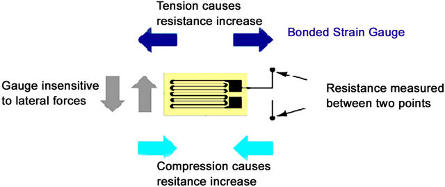
Figure 1. Source: www.circuitstoday.com. Forces of Compression and Tension.
combining smaller sensors in this way enables the surface under investigation to be more accurately modeled in terms of its size and shape.
Wiring the strain gauges in series helps cover different sized areas of investigation and helps improve the condition of the signal however, the size and quality of the signal received is too weak for data observations and capture. To overcome this problem, a further signal conditioning solution is required in the form of a “Wheatstone Bridge Circuit” [34]. The Wheatstone bridge works on the principle that, if all the resistances in each of its four arms are balanced, and it is supplied with a constant excitation voltage source across it, then the currents flowing through each arm of the bridge circuit will be balanced and hence no voltage difference will appear across its outputs.
Nonetheless, this provides a very low output value whilst the strain gauge is under a reasonable amount of tension, thus this value will be difficult to use given that it is not easy to distinguish between noise and the actual values. To address this design requirement a recognized solution is available in the form of a “Difference Amplifier” [35]. Before we consider this further, there is one last design requirement that needs to be considered when designing a Wheatstone bridge circuit.
A strain gauge applicator will never be at a zero output position when it is applied to the surface under investigation (i.e. ligament, tendon or the surface of the skin). This is because of the various body parts and the various patients that the applicator is likely to be fitted to. Therefore, a form of substitution is required that is built into the bridge circuit in the form of an “offset adjustment”. The simplest way of doing this is to connect a series of potentiometers in series with the strain gauge sensor, one for “fine adjustment” and one for “coarse adjustment”. By incorporating this facility into the circuit design, we can compensate for any slight bending of the patient applicator when it is being applied to the patient. It will be possible for the practitioner to adjust the output of the system to a “zero” level before monitoring begins. This will allow realistic results to be collected about the patient’s condition.
In order to further improve the condition of the output signal received from the bridge circuit, a “Difference Amplifier” is configured using a special resistor arrangement connected to the inputs and outputs [35]. By using this resistor arrangement, the functionality of the difference amplifier can be determined and the efficiency at which it performs. The resistance amplifier is determined by the values allocated to the circuit’s resistors. If all resistors are allocated the same value, then the amplifier will only have a Gain of “1”—there will be no amplification and will not be classed as an amplifier. It would however retain the advantage of performing “Common Mode Rejection” [39], which is used to effectively filter out any noise levels present at its inputs. It can do this because when the noise is present on both of its + and – inputs the inverted and non-inverted noise waveforms have the effect of mathematically canceling each other out.
The difference amplifier provides an improved and much safer value for input into the “Non-Inverting Operational Amplifier” [36] than the noise shrouded signal level that comes straight from the bridge circuit. Nonetheless, an amplifier is required to give an increased positive output voltage from a given positive input voltage. Such an amplifier is the “Non-Inverting” type, which can be formed by utilizing the operational amplifier “building block” and a suitable resistor configuration.
The design of the “Non-Inverting Amplifier” will have a “Gain”, which is determined by the value of the resistors in the voltage divider network of the feedback loop. In other words, the input is the expected maximum and the output is the required maximum. This will be discussed later in the paper.
3.3. Generic Wireless Sensor
After evaluating many sensors including MicaZ motes, SunSPOT’s, Ember and Meshnetic devices, SunSPOT’s were used in the prototype to process the analogue values from the strain gauge. SunSPOTS are 180 MHz 32-bit ARM920T core processors with 512 K of RAM and 4 M of flash memory. It has an onboard 2.4GHz radio with an integrated IEEE 802.15.4 radio. The battery is a 3.7 V rechargeable 750 mAh lithium-ion type that is charged through a USB port. Under normal use, the battery can last for about 7 hours. The sensor board provides several built in sensor functions, a 3-axis accelerometer, a temperature sensor, and a light sensor. Additional sensing functions can be added via the sensors six analogue inputs and analogue to digital converter, five general-purpose I/O pins and four high current output pins. In our prototype system the strain gauge is connected to the analogue inputs (A0, A1, A2, A3), which are designed to accept a 0 - 3 Vdc analogue voltage. The analogue values are converted to digital values and wirelessly transmitted to a base station.
Wireless transmission uses the IEEE 802.15.4 protocol at the 2.4 GHz transmission rate. This protocol helps prevent unwanted interference from other 2.4 GHz frequencies through multi-channel assignment and it rejects any signals that do not carry the correct authorization for connecting to its base station or free-range sensors, i.e. its master or its slaves. There are two types of communication possible with the SunSPOT. The first is the “radiogram” protocol, which acts like UDP, in that it, sends data out without guaranteeing delivery. This message is limited to a size of 256 bytes and is useful in delivering small broadcast messages. The second type is the “radio stream”. This protocol allows for much larger data transfers as well as guaranteed delivery. The radiogram protocol is sufficient for the data rates required and given that data is not sequentially dependent, there is no need to guarantee delivery given that similar values are being constantly transmitted.
4. Detecting Deterioration in the Musculoskeletal System
In this section, we discuss how the strain gauge and SunSPOT sensor can be combined to create a system capable of monitoring the mechanics of motion in an anatomically correct knee joint. In this way, the case study can be used to:
• Test the proposed design decisions and illustrate how the collective functionality described addresses the limitations with current approaches;
• Demonstrate how fine grain motion can be measured.
In developing the prototype, a multidisciplinary approach has been adopted whereby custom hardware is used to capture sensitive movements produced by the strain gauge sensor system. A SunSPOT base station is used to provide a bridge between the sensor network and middleware services. Software has been developed and installed on free standing SunSPOT’s (the sensor the strain gauge is connected to) to access and sample the data received from its analogue inputs. The middleware provides digital signal processing services for stream compositions, fact extraction, queries, inference and classification. The technical details for how the system was developed are discussed in more detail in the following subsections.
4.1. Strain Gauge Sensor
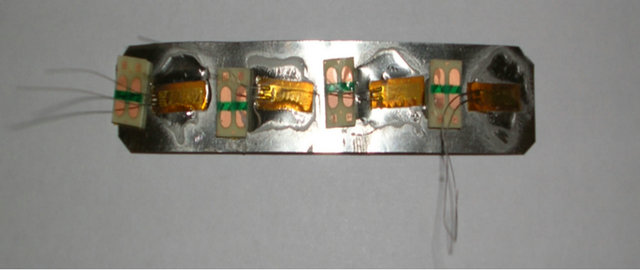
The strain gauges used in the prototype are 120 ohms each. It was necessary to connect four gauges together to create a single sensor with the overall value of 480 ohms as illustrated in Figure 2(a). This Increases the physical size and the sensitivity of the sensor. It also has the added advantage of increasing the overall electrical resistance of the Wheatstone bridge circuit, which in turn reduces the current demand of the onboard battery used by the SunSPOT sensor in the prototype. This therefore allows the periods between charging the SunSPOT battery pack to be increased.
When the strain gauge is at rest, the voltage supply is 3 volts (the 3 volts supplied by the SunSPOT). Consequently, the output voltage is 0 volts at rest (3 (480/480 + 480) – (480/480 + 480). If the strain gauge is placed under tension and the resistance of the active strain gauge increases (for example to 482 ohms), then the output voltage will be 0.003v. Obviously, 0.003v is too low to be used with the SunSPOT sensors. Such low values make it difficult to distinguish between noise and actual signals. The SunSPOT’s onboard Analogue to Digital Converter (ADC) requires a signal between 0 and 3 volts to be able to function correctly in outputting a readable signal to the base station. In order to achieve this a ‘Difference Amplifier’ is used to amplify the signal. A Gain of 10 was used to work out the resistors required. Therefore, selecting a fairly high (but standard) input resister (of 100K ohms) we get Rf = 10/100k = 1M ohm (Rf is the feedback resister). Using the output voltage and the feedback resister values the signal can be amplified to a more acceptable level, i.e. the voltage output is (0.003v – 0v) * 1M/100K = 003 V or 30 mV. By configuring the amplifier to have a gain of “10”, we can expect an output voltage of 0.03v for an expected input of 0.003v. This improves the quality of the signal and makes it a safer value for inputting into the Non-Inverting Operational Amplifier.
The correct voltage input required for the SunSPOT is 0.05v and the output voltage is 3v (SunSPOT max rated input voltage). Therefore, the required gain is 3/0.05, which is equal to 60. This can be achieved by using a minimum value of 1K ohms so as not to “ground” the Difference Amplifiers negative input, the value of the feedback resistor in K ohms is 60 – 1 = Rf/1, which means that Rf = 59K ohms. The nearest standard resister is 63K ohms and this was used in the final implementation.
4.2. SunSPOT Sensor
A free-range SunSPOT sensor is used to collect data from the area of investigation. A data collection point (laptop) connects to the sensor network using a USB base station SunSPOT sensor. The base station connects to the PIE middleware as a plug-in device, which receives and processes all data received. Sensors have the ability to operate in a disconnected mode—in this instance data is written to the SunSPOT’s internal flash memory—upon re-connection the data from the flash memory is streamed to the PIE middleware and processed. This allows the system to remain functional even when a person is shopping, catching a bus or taking a walk.
All SunSPOT’s communicate with each other over a multi-hop network and this allows data to be transmitted over a wider range. Any number of SunSPOTs can reside between the source and sink sensors to create a network of mesh routers. Free-range SunSPOTs, i.e. body and environment sensors, broadcast datagram packets to their nearest SunSPOT neighbour in order to try to establish a connection with that SunSPOT. This provides support for the required multi-hop methodology. The number of hops a SunSPOT can take to relay messages can be set to a maximum of 15 hops. Each SunSPOT receives information from the surrounding environment and then relays it to an available base station (if one cannot be found the information is stored within the sensors internal data store). Free-range SunSPOT’s stream data, via the base station and the implemented middleware services, and this allows data to be processed and presented to the application layer.
The strain gauge hardware is connected directly to the SunSPOT sensor. Software developed for the SunSPOT samples the analogue signal received on terminal “A0” of the ADC that is built into the SunSPOT. The sample rate is application specific and in the prototype is determined before the SunSPOT software is flashed. An easily visible bright LED on the SunSPOT has been programmed to flash when the SunSPOT is processing or sampling data. This provides information that the sensor is operational.
5. Evaluation
The prototype provides a working sensing device for the detection of movement in the individual components in the musculoskeletal system. The prototype system is illustrated in Figure 2. Figure 2(a) shows the strain gauge applicator; Figure 2(b) the Wheatstone Bridge, the Difference Amplifier, and the Non-Inverting Operational Amplifier; Figure 2(c) the strain gauge connected to the free-range SunSPOT; and finally Figure 2(d) shows the complete system configuration.
 (a)
(a)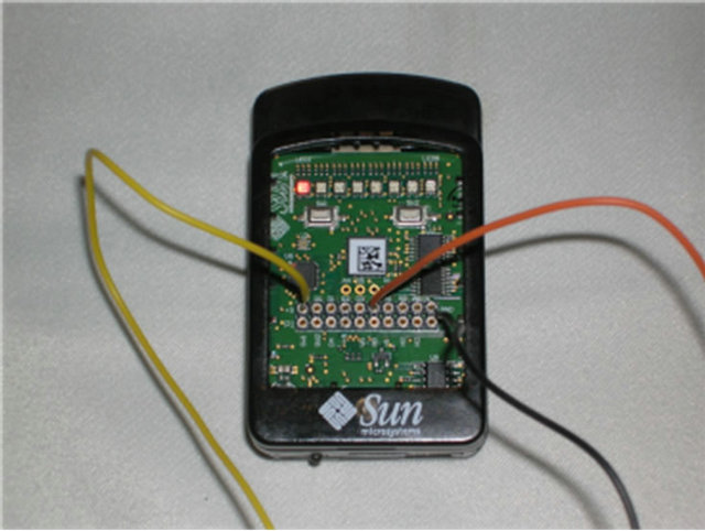 (b)
(b)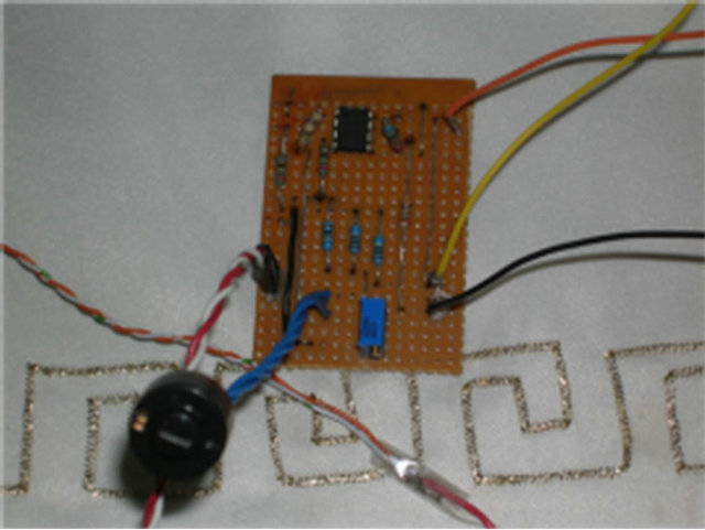 (c)
(c)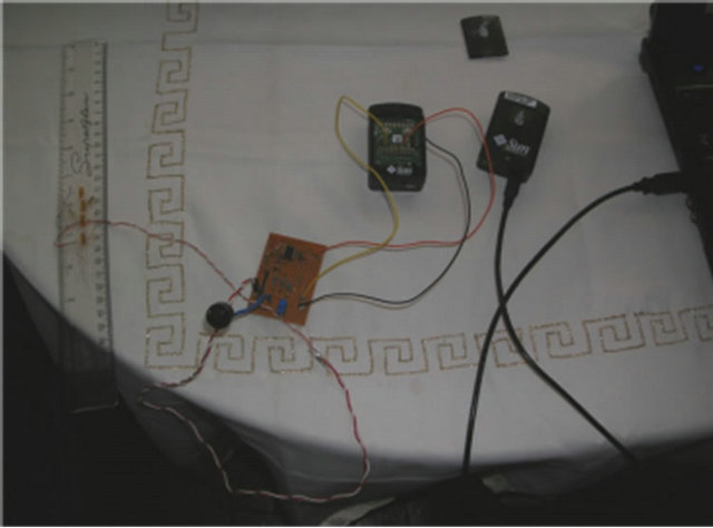 (d)
(d)
Figure 2. Prototype System. (a) Strain Gauge; (b) Circuitry; (c) Free-range SPOT; (d) Complete System.
In this section, we discuss how the wireless strain gauge sensor can be applied to various body parts for the purpose of movement analysis. In this way, the implementation can be used to:
• Test the proposed design and illustrate how highly sensitive information about movement can be obtained.
• Demonstrate how general wireless sensor technologies can be extended to include custom-made sensing functionality.
• Provide positive results to the use of strain gauge technology in progressive deterioration of the musculoskeletal system.
5.1. Artificial Knee Application
The flexible artificial knee illustrated in Figure 3 was fitted with the strain gauge applicator to monitor the movements of the Quadriceps tendon, the Patella and the Patellar tendon (ligament).
The applicator could just as easily be applied to the Lateral collateral ligament, the Medial Collateral ligament or the anterior cruciate ligament. Using this model the knee can be flexed as a normal knee would and then allowed to return to its normal resting position. For the purpose of the demonstration the knee was flexed 5 times to show the real-time data readings collected from the strain gauge sensor. A sample of the signal produced is shown in Figure 4 (the source of the data is from the strain gauge device attached to the analogue inputs of a SunSPOT sensor).
From the graph, it is possible to observe that the knee has managed to achieve constant bend amplitudes over a period of five consecutive exercises, with a rest period of approximately 5 seconds between each set. Although the graph is un-calibrated and uses generic values at this point, it would be possible to convert the x and y values to units of time and degrees respectively due to the linear characteristics of the strain gauges performance (we do this within the code to capture and increment 90-degree bends). The applicator is designed to fit with different body structures and capabilities. Using an offset facility (potentiometer that can be seen if Figure 2(b) a null position can be calibrated once the applicator has been fitted. This provides the therapist with a starting point of reference. The null or datum position can be set very easily by the therapist for each individual patient. Therefore, the same reference point can be set every time to remove the possibility of errors and inconsistencies from affecting the results.
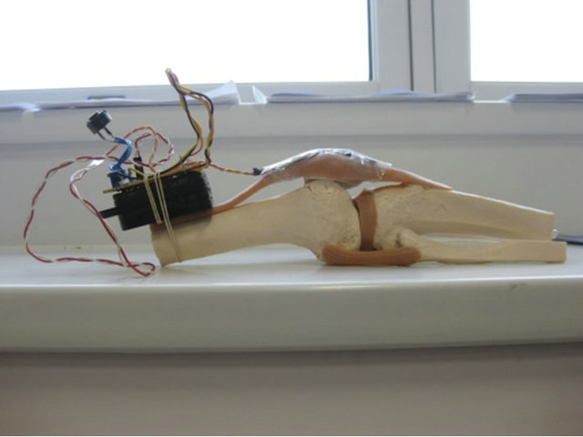
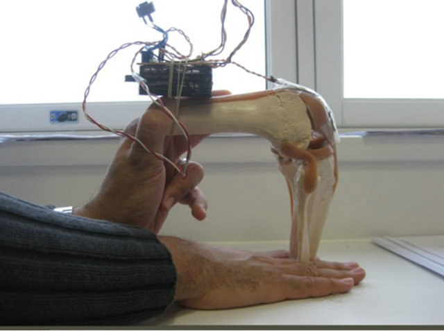
Figure 3. Strain Gauge attached to quadriceps tendon.
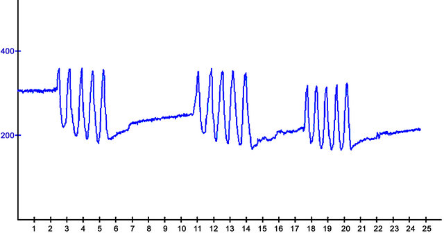
Figure 4. Real-time data stream from Artificial Knee Flexions.
5.2. The Physiotherapy Centre in Liverpool
The wireless strain gauge sensor was demonstrated at the Physiotherapy Centre located in Liverpool. Two chartered physiotherapists were presented with questionnaires, which they were asked to fill out during and after a full working demonstration of the strain gauge sensor. Some of the more notable comments that were made concerned the need to relate the readout display to units of degrees. This is because practitioners use a device called a “Goniometer”. This device resembles a large adjustable protractor, which is placed against the patient’s body joints to determine the extent to which that joint can bend i.e. its range. The demonstration proved valuable and highlighted the need to ensure that an electronic replacement, such as the one posited in this paper, should relate as closely as possible to what has been used before.
Other comments made were the possibility of displaying previous recordings on the screen and comparing them to current real-time readings. This would be useful in comparing a patient’s progress during their course of therapy. Furthermore, due to the nature of body joints, the therapist felt that software would need to be devised for each body joint. Whether this is the case requires further research. Overall, the comments made by the physiotherapists were in favour of a technological solution using the strain gauge sensor.
5.3. Performance Evaluation
Data from the strain gauge sensor attached to the knee were transmitted over the air to a multi hop network consisting of several free-range SunSPOT sensors. The total number used was five to cover a distance of 35 meters (enough to cover most locations with a standard home in the UK). A base station was connected to a notebook that provided a data collection point for the strain gauge sensor.
In the first experiment, the sensor was tested with multiple data transfer rates to identify throughput and power consumption. Each packet contained a sample of data that was 105 bytes in size. When transferring a single packet to a free range sensor up to 8 meters away the results show that 0.0002 (%) of the total power available is consumed. Increasing the data rate to 10 packets per second for a period of 1 minute, the results as shown in Figure 5 illustrate that the total power consumed is 0.0257 (%).
Increasing the distance to 16, 24, and 32 meters respectively and the time to 2, 3, and 4 minutes we find that the total power consumption used was 0.0514, 0.0815, and 0.1128 (%) when individual tests were run. Figure 6 shows that re-running the experiment with 1000 packets per second for 1 minute and 4 minutes respectively power consumption increases from 0.6053 (%) to 2.2351 (%).
These two results show a linear correlation between distance and power consumption over time. Note that these are stress tests and the number of packets and the distance between sensors may change in a real-world solution to conserve energy.
To cover the spread of communication around the home environment between one and five sensors were used to form a mesh network. The number of nodes used has an impact on both time and power consumption. Figure 7 shows distance verse power consumption readings. The first set of results show the power consumed over distances ranging from eight to thirty-two meters when ten packets per second were sent.

Figure 5. 10 packets of data sent per second.
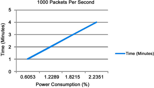
Figure 6. 1000 packets of data sent per second.
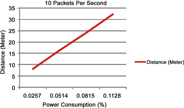
Figure 7. 10 packets of data sent per second.
Figure 8 shows the results for power consumed over distances between 10 and 40 meters when 1000 packets per second were sent.
The experiments provide valuable information for the deployment of any medical sensors and networks in body and personal area networks. They demonstrate that technology does make it possible to consider new and emerging technologies for real-time monitoring in healthcare applications and in particular those within the home.
6. Conclusions and Future Work
On-going developments in technology has helped to reduce the physical size and weight of devices and as we have seen, opened up new opportunities for their application in delivering unobtrusive healthcare services. Kinetic and kinematic systems are currently being used to measure and understand many different aspects of human gait and behaviour and this has been particularly useful in treating a number of different disease, like arthritis. Nonetheless, these systems are only capable of providing estimated information about rudimentary movement rather than detailed data on the mechanics of motion itself (tendons, ligaments and so on). This has not allowed the appropriate information to be used by healthcare professionals when making key clinical decisions. A number of interesting research initiatives that address aspects of this problem; however, we feel that our own ideas posited in this paper might provide a viable alternative that will significantly help support clinical judgement based on pliable strain gauge technology.
Nonetheless, improvements need to be made to the aesthetics of the applicator; possibly using an anti-bacterial removable outer coating. Second, embedding the sensor within the body was outside the scope of this paper; however, this issue needs to be considered in further work. Third, we did encounter some problems with the software freezing on the SunSPOTs after prolonged use— this needs to be further investigated. Fourth, the comments made by the physiotherapists during the evaluation of the system that different software versions are needed for each individual body part need to be investigated.
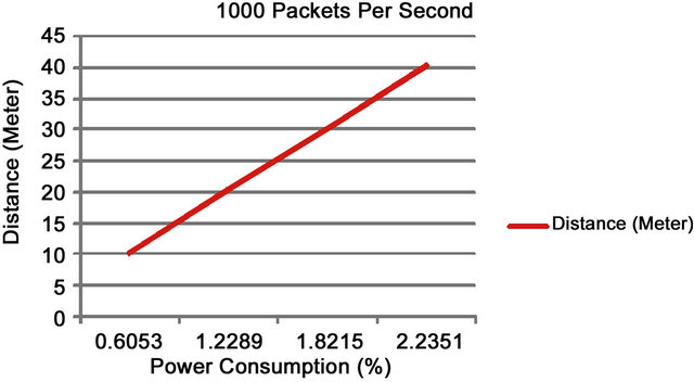
Figure 8. 1000 packets of data sent per second.
Fifth, the storage and stream reasoning middleware requires further testing on much larger data sets. Finally, we need to investigate battery-free sensor solutions for easier implantation, such as WISP sensors based on RFID technology.
7. Acknowledgements
The authors would like to thank the anonymous reviewers for providing highly constructive reviews, without which the paper would not have reached its current form. The authors would especially like to thank the Physiotherapy Centre in Liverpool for their help and constructive and positive criticism of the wireless strain gauge sensor.
REFERENCES
- R. C. Lawrence, et al., “Estimates of the Prevalence of Arthritis and Other Rheumatic Conditions in the United States,” Athritis and Rheumatism, Vol. 58, No. 1, 2008, pp. 26-35. doi:10.1002/art.23176
- H. Kwon, J. Cho and E. Lee, “EEG Asymmetry Analysis of the Left and Right Brain Activities during Simple versus Complex Arithmetic Learning,” Journal of Neurotherapy, Vol. 13, No. 2, 2009, pp. 109-116. doi:10.1080/10874200902885852
- J. van den Noort and S. J. Harlaar, “Evaluation of Clinical Spasticity Assessment in Cerebral Palsy Using Inertial Sensors,” Gait & Posture, Vol. 30, No. 2, 2009, pp. 138- 143. doi:10.1016/j.gaitpost.2009.05.011
- N. Chevrollier and N. Golmie, “On the Use of Wireless Network Technologies in Healthcare Environments,” 5th IEEE Workshop on Applications and Services in Wireless Networks. IEEE Computer Society, Paris, 2005.
- D. Geer, “Users Make a Beeline for Zigbee Sensor Technology,” IEEE Computer, Vol. 38, No. 12, 2005, pp. 16- 19. doi:10.1109/MC.2005.422
- P. Frehill, D. Chambers and C. Rotariu, “Using Zibee to Integrate Medical Devices,” 29th IEEE International Conference on Engineering in Medicine and Biology Society, IEEE Computer Society, Lyon, 2007.
- Y. M. Huang, M. Y. Hsieh and H. C. Chao, “Pervasive, Secure Access to a Hierarchical Sensor-Based Healthcare Monitoring Architecture in Wireless Heterogeneous Networks,” IEEE Journal on Selected Areas in Communications, Vol. 27, No. 4, 2009, pp. 400-411. doi:10.1109/JSAC.2009.090505
- J. Misic and V. B. Misic, “Bridging between IEEE 802. 15.4 and IEEE 802.11b Networks for Multiparameter Healthcare Sensing,” IEEE Journal on Selected Areas in Communications, Vol. 27, No. 4, 2009, pp. 435-449. doi:10.1109/JSAC.2009.090508
- M. A. Hanson, et al., “Body Area Sensor Networks: Challenges and Opportunities,” IEEE Computer, Vol. 42, No. 1, 2009, pp. 58-65. doi:10.1109/MC.2009.5
- A. P. Sample, et al., “Design of an RFID-Based BatteryFree Programmable Sensing Platform,” IEEE Transactions on Instrumentation and Measurement, Vol. 57, No. 11, 2008, pp. 1608-2615. doi:10.1109/TIM.2008.925019
- U. Varshney, “Pervasive Healthcare and Wireless Health Monitoring,” Mobile Networks and Applications, Vol. 12, No. 2-3, 2007, pp. 113-127. doi:10.1007/s11036-007-0017-1
- D. Bryant and O. Colgrave, “Knowledge and Informatics within Home Medicine (KIM): The Role of a ‘Home Health Hub’,” International Journal of Healthcare Technology and Management, Vol. 7, No. 5, 2006, pp. 335-347.
- G. Kortuem, et al., “Smart Objects as Building Blocks for the Internet of Things,” IEEE Internet Computing, Vol. 14, No. 1, pp. 44-51.
- A. Authier, et al., “A Proof of Concept for a Wireless Ambulatory Weight Bearing Measurement System in Rehabilitatin and Telerehabilitation Applications,” 3rd IEEE International Conference on Wireless and Mobile Computing, Networking and Communications, IEEE Computer Society, New York, 2007.
- M. Bailey-Van Kuren and D. Scarborough, “Mechatronic Applications in Pediatric Therapy Devices,” IEEE International Conference on Advanced Intelligent Mechatronics, IEEE Computer Society, Monterey, 2005.
- R. Bogue, “Exoskeletons and Robotic Prosthetics: A Review of Recent Developments,” Industrial Robot, Vol. 36, No. 5, 2009, pp. 421-427. doi:10.1108/01439910910980141
- R. A. R. C. Gopura and K. Kiguchi, “EMG-Based Control of an Exoskeleton Robot for Human Forearm and Wrist Motion Assist,” IEEE International Conference on Robotics and Automation, IEEE Computer Society, Pasadena, 2008.
- D. S. Anreasen, et al., “Exoskeleton for Forearm Pronation and Supination Rehabilitation,” 26th IEEE International Conference on Engineering in Medicine and Biology Society, IEEE Computer Society, Turkey, 2004. doi:10.1109/IEMBS.2004.1403778
- B. Rosenhahn, T. Brox and H. Seidel, “Scaled Motion Dynamics for Markerless Motion Capture,” IEEE Conference on Computer Vision and Pattern Recognition, IEEE Computer Society, Minneapolis, 2007.
- H. Zheng, N. D. Black and N. D. Harris, “Position-Sensing Technologies for Movement Analysis in Stroke Rehabilitation,” Medical and Biological Engineering and Computing, Vol. 43, No. 4, 2005, pp. 413-420. doi:10.1007/BF02344720
- H. Zhou and H. Hu, “Inertial Motion Tracking of Human Arm Movements in Stroke Rehabilitation,” IEEE International Conference on Mechatronics and Automation, IEEE Computer Society, Niagra Falls, 2005.
- H. Zhou and H. Hu, “Human Motion Tracking for Rehabilitation: A Survey,” Biomedical Signal Processing and Control, Vol. 3, No. 1, 2007, pp. 1-18. doi:10.1016/j.bspc.2007.09.001
- H. Zhou, et al., “Use of Multiple Wearable Inerail Sensors in Upper Limb Motion Tracking,” Medical Engineering & Physics, Vol. 30, No. 1, 2008, pp. 123-133. doi:10.1016/j.medengphy.2006.11.010
- E. Brostrom, S. Hagelberg and Y. Haglund-Akerlind, “Effect of Joint Injections in Children with Junvenile Idiopathic Arthritis: Evaluation by 3D-Gait Analysis,” Acta Paediatrica, Vol. 93, No. 7, 2004, pp. 906-910. doi:10.1111/j.1651-2227.2004.tb02688.x
- T. Pincus, “Taking Mortality in Rheumatoid Arthritis Seriously—Predictive Markers,” Socioeconomic Status and Comorbidity, Vol. 13, No. 5, 1986, pp. 841-845.
- C. L. J. Gonzalez-Juanatey, A. Testa, et al, “Increased Prevalence of Severe Subclinical Atherosclerotic Findings in Long-Term Treated Rheumatoid Arthritis Patients without Clinically Evident Atherosclerotic Disease,” Medicine, Vol. 82, No. 6, 2003, pp. 407-413.
- Y. B. Park, C. H. Lee, S. H. Lee, et al., “Atherosclerosis in Rheumatoid Arthritis: Morphologic Evidence Obtained by Carotid Ultrasound,” Arthritis & Rheumatism, Vol. 46, No. 7, 2003, pp. 1714-1719. doi:10.1002/art.10359
- M. J. Roman, A. Davis, et al., “Preclinical Carotid Atherosclerosis in Patients with Rheumatoid Arthritis,” Annuals of International Medicine, Vol. 14, No. 4, 2006, pp. 249-256. doi:10.7326/0003-4819-144-4-200602210-00006
- C. P. Chung, P. Raggi, et al., “Increased Coronary-Artery Atherosclerosis in Rheumatoid Arthritis: Relationship to Disease Duration and Cardiovascular Risk Factors,” Arthritis & Rheumatism, Vol. 52, No. 10, 2005, pp. 3045- 3053. doi:10.1002/art.21288
- S. W. Arms, et al., “Wireless Strain Sensing Networks,” 2nd European Workshop on Structural Health Monitoring, Munich, 2004.
- S. W. Arms, “MicroStrain Wireless Sensors Measure 3-D Force and Torque Data in Live Human Knee Replacement,” MstNews, Vol. 2, No. 7, 2007, p. 21.
- K. Saber-Sheikh, et al., “Feasibility of Using Inertial Sensors to Assess Human Movement,” Manual Therapy, Vol. 15, No. 1, 2010, pp. 122-125. doi:10.1016/j.math.2009.05.009
- R. A. Clark, et al., “Assessment of Mechanical Strain in the Intarct Plantar Fascia,” The Foot, Vol. 19, No. 3, 2009, pp. 161-164. doi:10.1016/j.foot.2009.06.001
- T, Kakaday, et al., “Advances in Telemetric Continuous Intraocular Pressure Assessment,” British Journal of Ophthalmology, Vol. 93, No. 8, 2009, pp. 992-996. doi:10.1136/bjo.2008.144261
- P. K. Chan, K. A. Ng and X. L. Zhang, “A CMOS Chopper-Stabilised Differential Amplifier for Biomedical Integrated Circuits,” IEEE Transactions on Circuits and Systems, Vol. 52, No. 11, 2005, pp. 2335-2347.
- M. M. Bani Amer, et al., “Contactless Method for Detection of Infant Apnoea,” Journal of Medical Engineering and Technology, Vol. 34, No. 5-6, 2010, pp. 324-328. doi:10.3109/03091902.2010.481034
- M. Merabti, et al., “Managing Distributed Networked Appliances in Home Networks,” Proceedings of the IEEE Journal, Vol. 96, No. 1, 2008, pp. 166-185. doi:10.1109/JPROC.2007.909922
- A. P. Santhanam, et al., “An Inverse Hyper-Spherical Harmonics-Based Formulation for Reconstructing 3D Volumetric Lung Deformations,” Comptes Rendus Mécanique, Vol. 338, No. 7-8, 2010, pp. 461-473. doi:10.1016/j.crme.2010.07.006
- N. Paddock and D. Behm, “The Effect of Inverted Body Position on Lower Limb Muscle Force and Activation,” Applied Physiology, Nutrition, and Metabolism, Vol. 34, No. 4, 2009, pp. 673-680. doi:10.1139/H09-056