Journal of Transportation Technologies
Vol.09 No.03(2019), Article ID:93704,12 pages
10.4236/jtts.2019.93022
Railway Transport Infrastructure Monitoring by UAVs and Satellites
Sergey I. Ivashov*, Alexander B. Tataraidze, Vladimir V. Razevig, Eugenia S. Smirnova
Remote Sensing Laboratory, Bauman Moscow State Technical University, Moscow, Russia

Copyright © 2019 by author(s) and Scientific Research Publishing Inc.
This work is licensed under the Creative Commons Attribution International License (CC BY 4.0).
http://creativecommons.org/licenses/by/4.0/


Received: May 30, 2019; Accepted: July 14, 2019; Published: July 17, 2019
ABSTRACT
Improving the rail transport security requires development and implementation of neoteric monitoring and control facilities in conditions of increasing speed and intensity of the train movement and high level of terrorist threat. Use of Earth remote sensing (ERS), permitting to obtain information from large areas with a sufficiently high resolution, can provide significant assistance in solving the mentioned problems. This paper discusses the possibility of using various means of remote sensing such as satellites and unmanned aerial vehicles (UAV), also known as drones, for receiving information in different ranges of the electromagnetic spectrum. The paper states that joint using of both these means gives new possibilities in improving railroad security.
Keywords:
Transport Infrastructure Monitoring, Remote Sensing, Satellite, Unmanned Aerial Vehicle (UAV), Aerial Photography, Radar Sensing, 3D Image Processing

1. Introduction
The railway transportation safety demands constant attention from the staff and management of company that operates the facility. This applies to the locomotive drivers’ condition monitoring, as well as to all services related to ensuring the smooth operation of the railway: manifestation that is called the human factor. These problems can be solved by a set of organizational and technical measures that improve discipline and working conditions of employees.
Unfortunately, there are still some technical factors, such as violation of the railway line integrity (rail rupture, destruction of railway arrow, etc.), which also require permanent monitoring. The another thing to mention is a problem of countering terrorist acts with the use of improvised explosive devices, which can lead to even more dire consequences. The use of remote sensing means such as piloted helicopters and drones could render substantial assistance in determining the scale of a railway catastrophe and ways of its elimination, including assistance to possible victims [1] [2] [3].
There is one more task connected to the topic of improving the safety of rail transportation. These are incidents related to natural phenomena including mudflows and avalanches, heavy snowfalls in the plains, and some others. Remote monitoring such phenomena could effectively help in its prediction and consequences management. To monitor and control the state of snow cover on the mountain slopes in avalanche prone areas, the UAV could be successfully used for reconstructing three-dimensional images of the terrain in the summer (without snow cover) and in the winter after heavy snowfalls. After comparison with such images. it will be possible to determine the height of the snow cover, and UAVs equipped with passive radar (radiometer) operated in centimeter or decimeter wavelengths will provide an opportunity to measure snowpack humidity [4]. These data could be added by measurements obtained from a ground-based radar network [5]. The combination of these factors (stockpile and humidity of snow) will allow creating a fairly accurate forecast of avalanches probability.
The railway is a transporter of dangerous consignments such as explosives, perilous for environment and poisonous chemical compounds, combustible and flammable materials. In case of an accident, it is necessary to promptly assess the scale of the disaster and make decisions on the prompt elimination of its consequences. The described examples widely show possible applications of UAVs and other remote sensing tools, including earth observation satellites, which can be used to ensure the safety of rail transportation.
The main goal of current paper is a comparison of the satellite and drone effectiveness in recording images of railway infrastructure in visual and microwave frequency range, and gives recommendation in their joint using. This matter was not analyzed before and main emphasis was mostly done on drones’ applications in infrastructure inspection [6].
2. Advantages and Disadvantages of Remotely Piloted Aircrafts
Recent years have been characterized by an increasing use of UAVs with the expansion of tasks ranges, which are solved with their help. While in the past UAVs were used exceptionally for military purposes, now their civilian use is becoming extremely important. Military original interest to drones, which arose in the late 60s, was stipulated by a desire to avoid the risk for the crew lives during reconnaissance flights. The disadvantage of these drones was the need of returning to “home” territory after the flight mission for the treatment of the recorded photographic films and decryption of the material. That reduced the relevance of obtaining information.
Hereinafter, the most successful development of UAVs was implemented in Israel (tactical and operational UAVs) and the United States (tactical and strategic UAVs). Progress in the designing a new generation of reconnaissance UAVs is primarily associated with the emergence of digital photography, including cameras functioning in different wavelength ranges, navigation and communication through satellites. This significantly improved the performance of on-board equipment, especially the weight and size, and allowed improving the parameters of the UAV such as endurance, range and height of flight. It should also be noted that the cost of the UAV has sharply decreased, and access to satellite information has been improved in recent years.
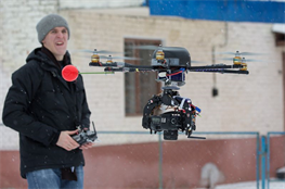
Modern drones for civil purposes are characterized by low operation cost and no need for stationary airfields with paved runways. As a rule, they are launched from simplest ground airfields, mobile catapults or directly from the operator’s hand. Remarkable progress has been achieved in the development of multi-rotor drone helicopters with electric power. UAVs of this type are characterized by simplicity of design and affordability. This is mainly due to the lack of such an essential for conventional helicopters a structural element as rotor hinge system, and the use asynchronous control of electric motors traction, that allows running the movement of the device in flight. Figure 1 shows a six-rotor UAV helicopter, which was used to obtain images of the Experimental Railway Ring (ERR) in Shcherbinka, Moscow region, in current project. Advantage of this type of UAV is also the fact that now their use in the exclusion zone of the railways at altitudes of less than 100 m does not require special permission for flights.
The disadvantage of multi-rotor electrical UAVs is a relatively short flight time usually less than an hour, and consequently restrictions on range and altitude of the flight. However, this is not essential when the operator controlling UAV flight is directly placed on the action place or near it. In this case, information about objects and events happening on earth surface can be obtained in real time and is compared with operator’s own vision, what is essential, for example for making decisions in the elimination of railway accident consequences. An increase of the drone flight time can be achieved by replacing the batteries during intermediate landings, although the range limit remains, and it is still sometimes a significant factor.
 (a)
(a)
 (b)
(b)
Figure 1. Helicopter-type UAV: (a) The UAV during the flight with a camera mounted in the gimbal; (b) The operator with the remote control of the UAV on the background.
3. Analysis of Satellite Resources for Obtaining Information
In the 1960s and 1970s the main users of photographic and radar satellite information were military, and this information itself was classified, but in recent decades a significant segment of consumers is the highly profitable civilian sector. In the first instance to the tasks to be solved by Earth observation satellites the following items should be included:
• Research of natural resources;
• Prediction, analysis and control of emergencies and their consequences;
• Geological exploration;
• Weather forecast;
• Control of the environment and its sources of pollution;
• Agriculture and prediction of harvest;
• Forestry and forest protection from fire and pests;
• Construction and other industries.
Remote sensing by satellites registers the radiation of the Earth’s surface in different ranges of the electromagnetic spectrum. For above mentioned tasks multispectral photography and side-looking radars are mostly used. In some cases the lasers are used especially in surveying for the measurement of Earth’s surface topography. Remote sensing data obtained from a spacecraft equipped with visible-range photographic cameras is characterized by a high degree of dependence on the atmosphere transparency and the times of day. Therefore, in order to remove these restrictions, remote sensing satellites equipped with side-looking radars have been widely developed. Radar image has worse resolution in comparison with optical one, but it has an ability to obtain images irrespectively of the weather and time of day, which is crucial for example for the navigation of ships on the Northern Sea Route during the polar night. Currently remote sensing satellites together with communication and navigation satellites constitute a significant segment of commercial space industry services. Often remote sensing satellites are created by organizations associated with the military industry of their own countries, which decreases the cost of their development due to the continuity of design solutions with military reconnaissance satellites.
Remote sensing satellites are usually launched into the so-called sun-synchronous orbit (sometimes called heliosynchronous), which has such parameters that the satellite on this orbit, passes over any point of the earth’s surface at about the same local solar time. Consequently, the angle of sun over the earth’s surface is approximately the same at all paths of the satellite above the same earth’s place. Permanent lighting conditions are very convenient for use in satellites receiving optical images of the earth’s surface including remote sensing and meteorological satellites. The parameters of the sun-synchronous orbits fall within the range: the height above the earth’s surface is 600 - 800 km, the period of rotation is 96 - 100 min, and the inclination of the orbit is about 98˚.
The main advantage of the remote sensing optical satellites is the ability to obtain high-quality multispectral images, which resolution can reach 0.3 m or lesser. Nevertheless, visual spectrum satellites are not able to function in night or cloudy weather. While the first shortcoming can still be potentially overcome, for example, by using infrared optics, the cloudiness, which in mid-latitudes in winter can hide the earth for weeks or even months, makes impossible using even infrared satellites. All-weather satellites are radar ones, even though they have the worst resolution. At the same time, radar provides additional opportunities, for example, obtaining images of the recorded signal in different polarizations or finding underground objects [7].
4. The Databases of Satellite Information
Currently, the results of satellite photography are widely distributed due to the accessibility and simplicity of work with them. For example, several sites in the Internet such as Google Maps (https://www.google.com/maps), Yahoo! Maps (https://maps.yahoo.com/) and others provide free access to photos recorded by satellites. Satellite images and topographic maps based on these images are widely used even for everyday household tasks as navigating private cars or calling a taxi. Some websites provide only the results of satellite imagery allowing working with databases of photographs: NASA World Wind, TerraServer-US, Space image, Landsat Look Viewer (USGS).
Although free information services provide images with a sufficiently high resolution, they still do not give an opportunity to obtain actual to the moment information because data in them are rarely updated. Photos for that websites were usually recorded in the warm season without the snow cover. Such images can be used for some types of analytical and theoretical works, but their drawbacks do not allow obtaining timely and relevant information about the event or object of interest. For getting actual information, you should contact the specialized organizations and place the order for recording satellite information. This is a chargeable service but it allows the customer getting information according to his own needs: time, place and conditions of photography, resolution of images and other parameters. The information may be provided as up-to-date one, i.e. recently received but also can be extracted from the database accumulated from previous years. The latter is important for information used in environmental studies, where it is significant to compare changes in the landscape over long period.
5. Comparison of Information Received from Different Sources
To compare satellite and airborne images of the railway transport infrastructure, the Experimental Railway Ring in Shcherbinka was selected. The choice of this object was related to the following circumstances. Firstly, ERR is well studied and located close to Moscow. Secondly, there were no difficulties with getting the permission for UAVs flights over the ERR territory because of its experimental status. Figure 2 shows the Experimental Ring image taken from the Google Maps database.
The center of the ERR ring is tagged with an arrow, its coordinates are 55.521373, 37.550190 (Northern latitude and Eastern longitude in degrees accordingly). Inside the Ring, a lot of summer country houses are located. The Experimental Railway Ring itself includes two double-tracks rings: outer and internal. The outer ring has the shape of a regular circle, and the inner ring contains a straight section.
A rail depot is visible in the lower right corner of this picture. A rectangle marks flight area of UAV which photos are used in this article. The another arrow in the rectangle marks the location of a water tower, which served as a landmark for UAV’s flights.
The enlarged image of the water tower obtained from the satellite is shown in Figure 3. This is maximal scale that the Google Maps site allows. Roof of the tower has a conical shape and is covered with galvanized steel sheets. Joins between the sheets have the form of vertical ribs. The ribbed shape of the roof is visible even in the satellite image.

Figure 2. Image of the railway experimental railway ring from Google Maps free database.
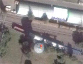
Figure 3. Large-scale satellite image of the water tower area on the experimental railway ring according to Google Maps.
The same area near the water tower was shot from the board of the UAV equipped with a Canon EOS 5D Mark II camera with EF-S 17-55 f/2.8 IS USM lens. Camera was mounted on a gimbal controlled by an operator, Figure 1. The result of the photographing from flight altitude about 70 m is shown in Figure 4. The difference between these two images consists in the location of the rail wagons on the tracks near the water tower that caused by different time of the shooting. The satellite image was recorded in summer, and drone flights were performed in autumn. They also differ in size and direction of the local objects shadow, as the images were taken at different positions of the sun on the celestial sphere. This fact stresses the importance of sun-synchronous orbits, which were mentioned earlier and are commonly used for remote sensing satellites. Another advantage of using sun-synchronous orbits is the ability to determine whether an object is being built or not, and at what speed it is being built, judging by the length of the shadow at the images obtained from different orbit passes of the satellite. Usually this method is used for the interpretation of images recorded by military reconnaissance satellite, but it also can be used for cadastral surveying, when it is necessary to allocate from a large array of images new and illegally erected buildings. In that case, to determine the newly erected buildings and their height change it is enough to subtract the images.
If we compare the resolution of the two above photos, it is obvious that the UAVs image has a much better resolution than satellite one. This is clear since the altitude of the orbits of remote sensing satellites is about 600 km in comparison with the same parameter for drones that equals a few hundred meters or several kilometers. UAVs have another advantage over satellites because they are less dependent on weather conditions. In the presence of cloudiness, it is impossible to shoot in the visible spectrum from satellites. While UAVs can hover below the lower cloud boundary and take pictures of the terrain.

Figure 4. Photograph of the water tower area on the ERR recorded by the UAV.
As mentioned earlier, only radar imaging is weather-independent. Two low-resolution images of the Experimental Ring district obtained from the Google Maps website and the European Sentinel-1 radar satellite database (Sentinel-1, https://sentinel.esa.int/web/sentinel/missions/sentinel-1/observation-scenario/archive) are presented in Figure 5.
At the lower part of both images Ostafievo airport (left in the pictures) and ERR (right) are seen. Both presented images have approximately the same scale, but the visible-range image contains more detail than the radar one. It is worth mention that radar image clearly depicts runways of the airport. The scale of both images can be easily estimated, because a diameter of the outer circle of the railway testing area is 1912 m.
The main advantage of radar, as it was mentioned earlier, is the ability to record images during the whole day and in all-weather conditions. In some cases, radar images may be the only source of information. In this regard, it can be concluded that to solve various problems in the interests of railway safety, it is important to have access to different sources of remote sensing information.
6. Reconstruction of 3D Models of the Railway Infrastructure Objects from a Set of 2D Images
Modern image processing software allows 3D environment model reconstructing from a set of 2D images. This gives an ability to view objects from different angles and heights. Such technology can be used in designing complex objects of the railway infrastructure (bridges, tunnels, etc.), as well as in solving problems of their safety.
In the recent time, the increasing interest in using 2D aerial images, collected by the UAV, in 3D model reconstruction is evident. It is very important to note that the UAV simplifies the process of taking images because operator can set the trajectory of the vehicle individually [8]. The multiple images are acquired by on board high resolution camera from multiangle and multiposition during the flight of the UAV.
 (a)
(a)
 (b)
(b)
Figure 5. Satellite images of the Experimental Railway Ring neighborhood: (a) low-resolution visible spectrum image the according to Google Maps; (b) radar image recorded by the Sentinel-1 satellite, EU.
The essence of an image is a projection from a 3D scene onto a 2D plane, during which process the depth is lost. The 3D point corresponding to a specific image point is constrained to be on the line of sight. From a single image, it is impossible to determine which point on this line corresponds to the image point. If two images are available, then the position of a 3D point can be found as the intersection of the two projection rays. This process is referred to as triangulation. The key for this process is the relations between multiple views which convey the information that corresponding sets of points must contain some structure and that this structure is related to the poses and the calibration of the camera. The task of converting multiple 2D images into 3D model consists of a series of processing steps which brief overview is given here. For a more extensive treatment the reader is referred to textbooks such as [9] [10].
Camera calibration consists of internal (focal length, coordinates of the principal point, distortion coefficients) and external (position and orientation) parameters, without which at some level no arrangement of algorithms can work Internal parameters are independent of outer conditions and do not change from one snapshot to another snapshot. In most situations, the internal parameters are calculated by shooting calibration objects, the geometry of which is pre-known, but also it can be computed without their use by applying a large number of images with common points [9]. External calibration is performed by triangulating key points common in two or more images.
To synthesize a 3D image, the problem of finding a match between key points in different images has to be solved. This task is accomplished by searching for points with minimum different descriptors-vector parameters describing the point. Thereby the SIFT algorithm describes each key point by a vector of 128 parameters identified on the basis of local gradients in the vicinity of the point [11].
One of the most efficient algorithms for filtering false correspondences of certain key points is RANSAC, Random Sample Consensus, [12]. The essence of the mentioned method is iterative search for the best transformation matrix (fundamental matrix) between N randomly selected key points in the first image and the corresponding points in the second one. From the initials set of key points RANSAC algorithm iteratively removes such points, deviation of which as a result of the applying the found transformation from the corresponding points in another image, exceeds the specified threshold.
Depth determination serves as the most challenging part in the whole process, as it calculates the 3D component missing from any given image—depth. The correspondence problem, finding matches between two images so the position of the matched elements can then be triangulated in 3D space is the key issue here. Once the multiple depth maps are determined they have to be combined to create a final mesh by calculating depth and projecting out of the camera. Camera calibration will be used to identify where the many meshes created by depth maps can be combined together to develop a larger one, providing more than one view for observation.
Complete 3D mesh may be the final goal, but applying the color from the original photographs to the mesh is usually required. In this paper the “mosaic” approach [13] was used to create the final texture which implies two-step approach: it does blending of low frequency component for overlapping images to avoid seamline problem (weighted average, weight being dependent on a number of parameters including proximity of the pixel in question to the center of the image), while high frequency component, that is in charge of picture details, is taken from a single image—the one that presents good resolution for the area of interest while the camera view is almost along the normal to the reconstructed surface in that point.
As the initial data for the reconstructing a 3D model of the earth surface with the objects of the railway infrastructure located on it, 176 drone photos were used. A few examples of the original photos are shown in Figure 6.
The resulting 3D model of the surface under different camera angles and from different heights is shown in Figure 7.
A more complete picture of the obtained model is demonstrated in the video, which could be downloaded from webpage [14]. Some limitations of the data, which have been used for reconstruction of 3D image, should be noted:
• A relatively small number of images;
• Non-optimal flight path of the UAV;
• Small overlap between images;
• Absence of information about the orientation of the UAV and camera, as well as data on GPS/GLONASS coordinates.
 (a)
(a)  (b)
(b)
Figure 6. Examples of original images recorded by the UAV.
 (a)
(a) 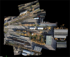 (b)
(b)
Figure 7. 3D reconstructed images of the railway depot.
Nevertheless, the resulting model sufficiently accurate reflects the features of the area where the photography was made. The model was constructed using the mathematical software Pix4D Mapper (Pix4Dmapper, https://pix4d.com/product/pix4dmapper/).
7. Conclusion
The analysis of the possibilities of using remote sensing satellites and UAVs equipped with various sensors showed that they could be an effective monitoring tool for ensuring traffic safety on the railways. Their information also can be used for solving other tasks, for example in the design and construction of railways infrastructure. The paper shows that the effectiveness of the Earth remote sensing can be increased by combining information recorded by satellites and UAVs, and with the use of the modern image processing means, it becomes possible to build synthetic three-dimensional images of railway infrastructure.
Acknowledgements
The study was performed with financial support of the Russian Foundation for Basic Research, Project No. 17-20-02086. The authors express their gratitude to the staff of the Experimental Railway Ring for assistance in conducting of UAV flights for obtaining the necessary information.
Conflicts of Interest
The authors declare no conflicts of interest regarding the publication of this paper.
Cite this paper
Ivashov, S.I., Tataraidze, A.B., Razevig, V.V. and Smirnova, E.S. (2019) Railway Transport Infrastructure Monitoring by UAVs and Satellites. Journal of Transportation Technologies, 9, 342-353. https://doi.org/10.4236/jtts.2019.93022
References
- 1. Flammini, F., Pragliola, C. and Smarra, G. (2016) Railway Infrastructure Monitoring by Drones. International Conference on Electrical Systems for Aircraft, Railway, Ship Propulsion and Road Vehicles & International Transportation Electrification Conference, Toulouse, 2-4 November. https://doi.org/10.1109/ESARS-ITEC.2016.7841398
- 2. Eyre-Walker, R.E.A. and Earp, G.K. (2008) Application of Aerial Photography to Obtain Ideal Data for Condition Based Risk Management of Rail Networks. The 4th IET International Conference on Railway Condition Monitoring, Derby, 18-20 June 2008. https://doi.org/10.1049/ic:20080353
- 3. Francesco, F., Naddei, R., Pragliola, C. and Smarra, G. (2016) Towards Automated Drone Surveillance in Railways: State-of-the-Art and Future Directions. International Conference on Advanced Concepts for Intelligent Vision Systems, Lecce, 24-27 October 2016, 336-348. https://doi.org/10.1007/978-3-319-48680-2_30
- 4. Schwank, M. and Naderpour, R. (2018) Snow Density and Ground Permittivity Retrieved from L-Band Radiometry: Melting Effects. Remote Sensing, 10, 354. https://doi.org/10.3390/rs10020354
- 5. Skofronick-Jackson, G., Kim, M., Weinman, J.A. and Chang, D.-E. (2004) A Physical Model to Determine Snowfall Over Land by Microwave Radiometry. IEEE Transactions on Geoscience and Remote Sensing, 42, 1047-1058. https://doi.org/10.1109/TGRS.2004.825585
- 6. Besada, J.A., Bergesio, L., Campaña, I., Vaquero-Melchor, D., López-Araquistain, J., Bernardos, A.M. and Casar, J.R. (2018) Drone Mission Definition and Implementation for Automated Infrastructure Inspection Using Airborne Sensors. Sensors, 18, 1170. https://doi.org/10.3390/s18041170
- 7. Koyama, C.N. and Sato, M. (2015) Detection and Classification of Subsurface Objects by Polarimetric Radar Imaging. IEEE Radar Conference, Johannesburg, 27-30 October 2015, 440-445. https://doi.org/10.1109/RadarConf.2015.7411924
- 8. Bulgakov, A., Evgenov, A. and Weller, C. (2015) Automation of 3D Building Model Generation Using Quadrotor. Procedia Engineering, 123, 101-109. https://doi.org/10.1016/j.proeng.2015.10.065
- 9. Hartley, R. and Zisserman, A. (2004) Multiple View Geometry in Computer Vision. 2nd Edition, Cambridge University Press, Cambridge. https://doi.org/10.1017/CBO9780511811685
- 10. McGlone, J.C. (2013) Manual of Photogrammetry. Sixth Edition, American Society for Photogrammetry and Remote Sensing, Bethesda, Maryland, USA, 1318 p.
- 11. Lowe, D.G. (1999) Object Recognition from Local Scale-Invariant Features. Proceedings of the International Conference on Computer Vision, Kerkyra, 20-27 September 1999, Vol. 2, 1150-1157. https://doi.org/10.1109/ICCV.1999.790410
- 12. Fischler, M. and Bolles, R. (1981) Random Sample Consensus: A Paradigm for Model Fitting with Applications to Image Analysis and Automated Cartography. Communications of the ACM, 24, 381-395. https://doi.org/10.1145/358669.358692
- 13. Maenpaa, T. and Pietikainen, M. (2005) Texture Analysis with Local Binary Patterns. In: Handbook of Pattern Recognition and Computer Vision, 3rd Edition, World Scientific, Singapore, 197-216. https://doi.org/10.1142/9789812775320_0011
- 14. http://www.rslab.ru/pubdir/1.wmv