Journal of Biomaterials and Nanobiotechnology
Vol.3 No.3(2012), Article ID:20562,8 pages DOI:10.4236/jbnb.2012.33036
Investigation of the Effect of Local Electrical Stimulation on Cells Cultured on Conductive Single-Walled Carbon Nanotube/Albumin Films
![]()
1Center for Probe Microscopy and Nanotechnology, National Research University of Electronic Technology, Moscow, Russia; 2Cell Culter Laboratory, Ivanovskiy Institute of Virology, Moscow, Russia.
Email: *vkn@nanotube.ru
Received May 13th, 2012; revised June 16th, 2012; accepted June 29th, 2012
Keywords: Conductive Composite; Human Embryonic Fibroblasts; Bovine Serum Albumin; Electrical Stimulation; Proliferation
ABSTRACT
In this study we have developed a biocompatible current-conductive coating based on carbon nanotubes and bovine serum albumin and have shown its efficiency in culturing cells in vitro. We investigate the proliferation of human embryonic fibroblast (HEF) cells, which were subjected to electrical stimulation when cultured on carbon nanotube surface. A weak increase in proliferation is demonstrated at stimulating field pulses up to 100 mV. It is assumed that the transport mechanism accompanied by higher synthesis of proteins and their polymerization may increase proliferative activity at low voltages. At higher voltages the motility and spatial organization of HEF cell is observed. As a result, a novel technique of supplying the cells with electric field through a system of micro and nanosized electrodes and a biocompatible composite have been developed.
1. Introduction
For the past five decades electrical stimulation effect on accelerated regeneration of bone tissues, skin injury repair and targeted drug delivering has been widely investigated [1]. The main problem with conventional methods of supplying an external electric field is that it is impossible to localize the field in the healing area. In general case a considerable area of the body is exposed to electrical stimulation. Extending the work area and the distance between electrodes and the healing area implies increasing of electrical field intensity, required for stimulating individual cells. This problem may be solved by using implanted electrodes localizing the electric field in the necessary area of the body. In this case, standard materials which are used for electrodes, for example, stainless steel, platinum or titanium can be replaced by nonmetallic, more biocompatible and conductive materials [2].
Carbon nanotubes, in particular, are one of promising nanotechnology products, and since their structure is geometrically close to collagen [3]—the main protein of the mammal connective tissue, they can be used in biological engineering as a scaffold material for tissue regeneration [4]. Unique electronic properties, high mechanical strength, excellent flexibility and large specific surface area of nanotubes make them suitable for creating novel biocompatible composite materials for tissue engineering [5].
Producing a scaffold material is widely investigated in cell seeding and growing applications [6]. At present, there are a number of works on producing composite materials based on nanotubes for bioengineering, and namely, for bone and cartilaginous tissue regeneration [7,8], and fibroblast growth investigation [9].
In osteoblast growth an additional possibility of delivering an electrical signal to cells through the culture medium and current-conductive composite containing nanotubes is used. In this case, a 46% increase in proliferation [10] was observed after electrical stimulation. Various applications of nanotubes and current-conductive composites based on them in neurosurgery [11] are also considered. For further developments in integrating nanotubes in living tissues, a number of serious problems like improving the biocompatibility and biodegradation of nanotubes as well as producing composites based on protein matrices must be solved [12]. Nevertheless the correlation analysis of the local pulse electric field stimulation effect on proliferation and electric fields mediate motility (galvanotaxis) on nanotube substrates has not been done so far.
This work suggests the development of composite based on single-walled carbon nanotubes (SWNT) and bovine serum albumin (BSA) to form conductive substrates. A device for local field supply to cells through nanosized electrodes has been developed. Spatial organization and proliferation of human embryonic fibroblasts (HEF) cultured in vitro under the influence of a pulsed local electric field are studied. The research shows that by stimulating cells through nanosized electrodes at low amplitudes of electric field intensity and small signal oscillation rates proliferation raises by 26%. Whereas increasing the field strength leads to motility and HEF cell reorganization according to electric field gradient.
2. Materials and Methods
2.1. Choosing the Material
Most commonly the material of carbon nanotubes obtained by arch discharge or laser evaporation of graphite or by chemical decomposition of carbonaceous vapor is a powder that should be purified, filtered from undesirable impurities (such as amorphous carbon, defective nanotubes, catalyst particles), as well as functionalized, in some cases, to obtain nanotube properties required for the specific application. However in this case, preparation of solutions is needed. It is well-known that nanotubes can be dissolved in most polar and nonpolar solvents, so to dissolve SWNTs obtained in the arc discharge, it is necessary to split bunches and bundles of them which were formed in the process of growth. The most effective way to do that is additional functionalizetion of nanotubes by surfactant materials (SM), which allows a stable colloidal solution of single nanotubes of any concentration to be achieved. These SM solutions are ideal to form thin percolated films on any surfaces. By regulating nanotube concentration in the solution one can regulate the thickness of the film to be formed on the surface. As we have shown previously [13], the nanotube orientation and density on the surface can be controlled while using different deposition techniques: dipping, pulling, centrifugation, sputtering.
To prepare conductive composites based on nanotubes one can use their mixtures with proteins as a natural polymer providing a biocompatible substrate and improved adhesion of cells [12]. Albumin is one of the most important transport proteins, which regulates metabolism functions in cell growth and tissue regeneration. In this research we suggest using BSA protein molecules as a surfactant to form a biocompatible conductive layer on the cover-slip. Previously, a composite consisting of nanotubes and albumin was examined as a scaffold-forming material in implants in cartilaginous tissue regeneration [14,15].
2.2. Substrate Fabrication
2.5 mg of 99.5 mass % SWNT provided by A. V. Krestinin (Institute of Problems of Chemical Physics of RAS, Moscow, Russia) were placed into a BSA aqueous solution (10 mg of BSA in 5 mL of water) and dispersed in a Branson B300 (Branson Ultrasonics, Danbury, CT, USA) ultrasonic bath (34 kHz, 50 W) for 10 hours. Typical length of nanotubes was less than 1000 nm after ultrasonic treatment. Nevertheless the CNT combines in bundles up to 5 mm long and about 10 nm in diameter. Cover-slips, 24 × 24 mm in size, 0.13 - 0.17 mm thick were preliminary mechanically washed with cotton in 2-propanol, then they were kept in 2-propanol for 15 minutes and placed in ultrasonic bath. On one of the surfaces of the cover-slip two gold contact pads, 30 nm thick, were formed by magnetron sputter deposition (Emitech K575X, Quorum Technologies, Ringmer, UK). About 25 mL of nanotube solution in albumin were applied onto this surface with a microdispenser and a thin film was made to cover the whole slip surface by rodcoating method, then the film dried for 15 minutes at 40˚C. To improve the film adhesion and conductance the structure was annealed in the air at a temperature of 150˚C for 2 minutes. Figure 1 shows the photography of a cover-slip with the current-conductive SWNT/BSA coating formed. The resistance of the structures investigated in the work ranged from 100 kOhm to 10 MOhm, but in the experiment for proliferation estimation at low stimulation voltage we’ve used a set of samples with close resistance (several MOhm).
It should be noted that the samples of SWNT/BSA film obtained not only possessed conductance but also transparency within the visible range at a level of 85% - 90%.
2.3. Electrical Stimulation System
To carry out experiments with electrical stimulation of
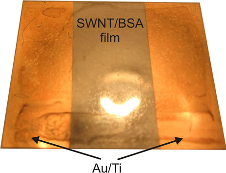
Figure 1. Cover-slip with gold electrode system covered by SWNT/BSA film.
cells, a custom system for supplying electrical signals which comprises a 6-well plate, a signal generator and an oscilloscope has been developed. The plate cover has a breadboard with a connector fixed on it. Over each of these 6 wells two sharp needle electrodes with diameter 0.3 mm made of a 40KHNM-VI biocompatible alloy with a gold electrolytic coating (Doriva, Moscow, Russia) were placed. The electrodes were connected in pairs in 2 rows of 3 wells each to provide lead output to the signal generator connector. On the one hand, this ensured biological compatibility with the medium, on the other, the contact area of the whole surface of the needle with the cultural medium was much smaller than the area of the modified cover-slip (~40 times), which minimized the current contribution through the medium. In each set we’ve used 5 wells for experiment and one for control (Figure 2). To apply voltage we used a RIGOL DG1022 generator (Rigol Technologies Inc., USA).
The generator can be set to arbitrarily shaped stimulatory signal, as well as to produce two independent signals in parallel. Due to the modified cultural plate design, the system was able to send a signal directly to the cells through the SWNT/BSA film. The voltage generator was connected with the plate by means of a flexible cable with the core diameter of 0.1 mm, which could be easily placed in the CO2 incubator. Figure 2(b) shows the schematic diagram of the connection.
For each experiment we used five cover-slips covered by SWNT/BSA film: two slips—to minimize statistical error for proliferation measurements, one—for morphology investigation, one—for microscopy analysis, one was cultured without voltage applied and used as control. Also there was one pristine cover slip with voltage applied through the medium.
2.4. Cell Culture
HEF—human embryonic fibroblast cells were provided by the Tissue Cultures Laboratory of Ivanovskiy Institute of Virology, a Federal State Institution of the Ministry of Health and Social Development (Moscow, Russia), were cultured in the electrical stimulation unit (Figure 2(a)). Linbro 6-well plates (MP Biomedicals, Solon, OH, USA) were used as a culture dish. The unit, plates, and coverslips were sterilized in 70% ethanol solution for 10 minutes with the follow-on 20-minute ultraviolet treatment. Immediately prior to the incubation cover-slip samples were rinsed in the Eagle culture medium for 10 min to eliminate contaminants. After removing this medium the HEF cells in the concentration of 105 cells/mL were added into each well in the amount of 1 mL of the Eagle medium with 10% FBS (fetal bovine serum) and incubated for 24 hours in a thermostat with 5% CO2 at 37˚C.
After a 24 hour incubation with no voltage applied, a
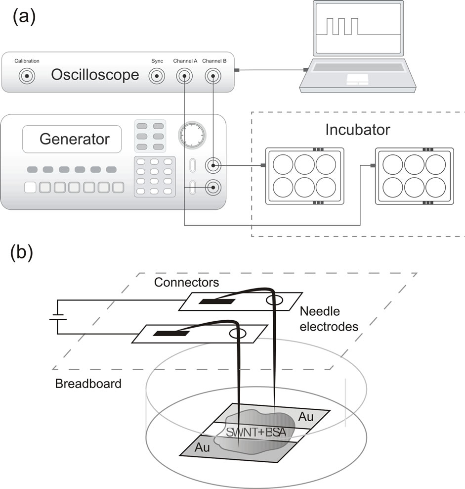
Figure 2. Electrical stimulation system schema. (a) A plate of 6-well plate with a system of gold electrodes. The electrodes are placed into the medium to provide a contact with the substrate during electrical stimulation; (b) Schematic diagram of connecting components of the electrical stimulation system.
signal of 5 pulses was sent with 5 ms pulse duration, 5 ms spacing between pulses, 1 s interval between pulse groups. The main pulse characteristics were chosen with previous experiments in electrical stimulation of growing fibroblasts with standard two carbon electrode unit taken into consideration [16]. We have done 3 sets of experiments with different amplitudes 10, 50, 100, 200, 500, 5000 mV applied to the cells. Since the resistance of wires and electrodes is relatively small, the main voltage drop through SWNT/BSA film was expected. Despite the fact that the resistance of the fabricated SWNT/BSA film samples varied, in the experiment, for proliferation estimation we used samples of the same order of resistance (from 3 to 10 MOhms). The electrical stimulation lasted for 48 hours. In addition, we conducted an experiment where the current was applied to needle electrodes placed into culture medium with cover-slips in the absence of a conductive substrate. As expected, the size of the electrodes was relatively small for a significant current to leak through the medium.
2.5. Proliferation and Morphology Investigation
The proliferation was defined by means of a modified MTT assay. For this purpose, the Eagle medium with 10% FBS was removed after electrical stimulation, the cover-slips were moved to a clean plate, where 1 mL of the Eagle medium and 200 ml of MTT solution (with the initial concentration of 5 mg/mL) were added. The coverslips were incubated in the thermostat with CO2 at 37˚C for 4 hours. Then the medium with MTT removed and 1 mL of DMSO was added into each well to dissolve MTT-formazan reduced by the cells. Cell precipitates with MTT-formazan on glass samples were resuspended for 5 min and the solution absorbance was measured by a Titertek Multiscan Plus photometer (Flow Laboratories, Helsinki, Finland) on a 492 nm wavelength. To achieve that, 1 mL of DMSO with the dissolved formazan was transferred to a 96-well plate, with a 100 mL per well dosage. A structure with gold electrodes and a SWNT/ BSA film applied, which was in one of the wells of a 6- well plate, but without voltage supply was used as a control.
The cover-slips with a SWNT/BSA coating were investigated with atomic force microscope Solver P47 (NT-MDT, Moscow, Russia) in a semi-contact mode before and after the cell growth. For AFM measurements samples were removed from culture medium, fixed in 2.5% glutaraldehyde for 30 minutes and washed in the phosphate buffer saline (PBS) 2 - 3 times, 2 minutes each, then dehydrated in 50%, 70% and 96% solution of ethanol for 2 min in each one. Some of the samples after electrical stimulation were stained with azur-eosine for morphology study.
3. Results
First of all we have investigated the quality of film preparation methods. Looking at the surface topography shown at Figure 3 one can say that this method produces a sufficiently uniform film. As nanotubes are surrounded with albumin molecules during water solution preparation, CNT functionalization and additional binding may occur in the process of supersonic treatment [17]. Thus, originating non-covalent bonds between nanotubes and albumin, and CNT functionalization may result in higher
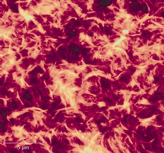
Figure 3. AFM image of a SWNT/BSA film on the coverslip surface after solution deposition and annealing at 100˚C (bar 5 μm). The film thickness is ~100 nm.
uniformity of nanotube distribution in the nanomaterial array, as well as in structuring albumin itself on the nanotube surface [18]. However, it can be seen from the image, that bunches do not split completely: the film consists of bundles up to 10 nm in diameter.
Annealing at 100˚C for 2 minutes increases the conductance of the structures, but we also assume that annealing may not cause the protein denaturation, as SWNTs increase thermal stability of proteins [19].
Studying the morphology of HEF cells grown on glasses with SWNTs after electrical stimulation showed that the culture consisted of fibroblast-like cells with oval nuclei having big nucleoli, 1 - 4 in a nucleus, the cytoplasm was low-reticular, but there were some nanotube clusters varying in form and size (Figure 4). At 100 mV and higher voltages some changes in the cell morphology can be seen. On the whole, one can observe a cluster of cells on spots with thicker nanotube film and their characteristic orientation along the gradient lines of the electric field, while the voltage increases up to 100 mV (Figure 5). More over at voltages higher then 100 mV cell tend to aggregate in large clusters in the middle of the substrate.
AFM investigation was carried out on fixed cells. As nanotubes and cell membranes have different stiffness factors, it was possible to distinguish nanotubes from cells with AFM phase mode. It was found that nanotubes covered the cells on top, especially in the area of cell outgrowth formation (Figure 6). Based on AFM measurements we can suggest that while growing cells not only developed on the surface of the SWNT/BSA composite, but also nanotubes are attaching to the edges of cell’s membrane (Figures 6(a) and (b)), providing better adhesion.
The Figure 6 demonstrate the results for 10 mV pulse electrical stimulation, the same results of nanotube adhesion observed for all range of low voltage applied. On the
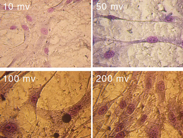
Figure 4. Micrographs of HEF cells fixed on the third day after seeding on cover-slips modified with a SWNT/BSA film (magnification ×400). For the last 48 hours culturing took place at 10, 50, 100, 200 mV voltages. On the third day cell processes started to connect, but contact inhibition was absent.
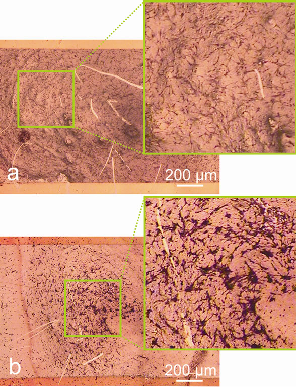
Figure 5. Micrographs of HEF cells fixed on the third day after seeding on cover-slips modified with a SWNT/BSA film (bar 200 μm). The last 48 hours the pulse electric stimulation was applied with amplitude 10 mV (a) and 200 mV (b).

Figure 6. 3D visualization of AFM data (a); close-up view (b); 2D AFM (c) and phase contrast image (d) of HEF cells interaction with nanotubes on a cover-slip modified with a SWNT/BSA film (bar 10 μm).
whole, the AFM topography shows quite good adhesion of cells to the film, which indirectly confirms biological compatibility of the material.
Figure 7 shows the MTT-test absorbance for cells grown at different stimulation signal applied. It can be
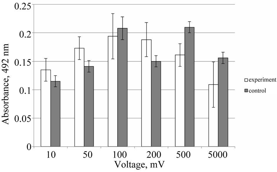
Figure 7. Proliferation factor of HEF cells being cultured for 72 hours on cover-slips modified with a SWNT/BSA film versus different voltages supplied for the last 48 hours. Control is a cell growth at cover-slips modified with a SWNT/BSA film without field applied.
seen that at low values of the supplied voltage the proliferation of HEF cells increases. While at voltages higher then 100 mV it began to decline. It should be noted that variation in control samples (without voltage applied) indicates the nonidentity in properties of CNT/BSA films. However, when voltage is applied, the effect of electric field prevails over the contribution of the inhomogeneity of the film which leads to a strong correlation between the electric voltage and proliferation. Taking into account the error in experiment is an order of variation of control sample it can be concluded that weak effect in proliferation is demonstrated at stimulating field pulses.
It should be noted that some authors described interaction of MTT solutions with the CNT suspension resulting in MTT solution transformation into MTT-formazan [20, 21], however, in this research carbon nanotubes were fixed on the substrate surface by the precipitation method, mentioned above. In precipitation with albumin a stable compound is formed which makes a film on the substrate surface, this material does not react with MTT and does not cause MTT transformation into MTT-formazan. To prove this fact we compared the absorbance of solutions from cover-slips samples with a SWNT/BSA film, to the absorbance of solutions where clean cover-slips were kept. For this purpose 2 types of substrates were prepared: glasses with a SWNT/BSA coating formed in accordance with the above-mentioned technique and reference glasses without a coating which were washed in 2-propanol using supersonic treatment for 20 min.
The substrates were incubated in the Eagle cultural medium for 42 hours, then, the MTT assay was used, similarly to the procedure described above, i.e. the glasses were kept in the medium with MTT for 4 hours. Then, they were removed from the medium and DMSO was added. The experiment showed, that optical density values for the solution with SWNT and BSA coatings did not differ from those for the solution with clean glasses within reasonable errors (data not shown), which proves that MTT transformation into MTT-formazan did not occur in that case, due to the absence of living cells which would be able to convert it.
4. Discussion
We suggest the CNT/BSA substrate brings a significant contribution to the cell proliferation. Nonuniformity of the conductive material we used, which consists of a great number of high-resistance point contacts of nanotubes with each other, should be taken into account (Figure 8). First of all CNT/BSA film consist of percolated nanotube branches and bundles spreading in BSA. The distances between the neighboring nanotubes in film vary from 1 nm (the conductivity channels) and up to 200 nm according to AFM measurements (Figure 3). Thus there was a great local electric field gradient between the neighboring nanotubes in a film, so the force affected at charge carries (ions) in electrolyte is rather high and proportional to grad (E2). Thus changing in voltage from 10 mV to 5 V increases the electric force affected on ions up to six orders of magnitude.
A weak rising proliferative activity of cells at low voltage supplied can be explained by the theory of increasing synthesis of protein and DNA, and external electric field influence on internal functional mechanisms in the cell.
As shown by Schimmelpfeng et al., a low-frequency electrical stimulation enhances cell proliferation due to processes defined by secondary intermediaries [22]. Thus, if we consider the molecular mechanism of cell proliferation, we can expect that electrical signals activate extracellular signal molecules at the moment of pulse application in the process of incubation. Extracellular signal molecules can be linked with receptor proteins on cell surfaces, and then the signals can be sent by molecular switches to intracellular transport proteins [23]. Due to the standard mechanism of information transfer inside the cell the signal is transferred to the necessary proteins. According to the results obtained, this type of mechanism at the molecule level becomes most effective for HEF cells at voltages ranging from 10 to 100 mV.
Reduction of cell growth velocity and development at high intensities of electric field may be attributed to the raising temperature of the medium, with current flowing through the nanotube carrier as well as through the medium, when significant potential differences are applied [24]. Since the energy transfer is mainly determined by the power consumed by the system, at low voltages it is rather small value. As the voltage increases, the energy rises quadratically, depending on the potential [25]. Nevertheless, the medium temperature value at low voltages (mV) is under energies of thermal vibrations for short
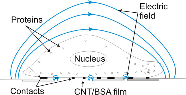
Figure 8. Schematic drawing of HEF cell on nanotubes based film in electric field.
electric pulses. With the lack of sufficient heat effect, one can consider an alternative molecular theory of relation between an electric field and cell proliferation [24]. We suggest that as potential in nanotube/nanotube contacts raises, the current through SWNT/BSA film also grows according to Fowler-Nordheim formula [26]. The energy dissipation in these contacts can be an order higher than in the body of the nanotube as a whole. When the voltage applied to the conductive SWNT/BSA film, reaches the 200 mV threshold, cell inhibition can be observed. At the same time there is movement of the cells in an electric field (galvanotaxis) with voltage over 100 mV applied (Figure 5(b)). This effect needs further investigation of composites themselves.
5. Conclusion
Thus, we have developed a current-conductive structure based on SWNT and BSA composite. The structure provides a good contact with culturing cells. It seems that the applied potential has no significant effect on cell proliferation. It is shown that the voltage under 500 mV weakly raises the proliferation of HEF cells by 26% without having a prominent influence on their morphology. The transport mechanism accompanied by accelerated synthesis of proteins and their polymerization may be a likely reason for cell proliferation augmentation at low voltages. As the voltage rises, the proliferation declines and cell morphology changes (cell transformation can be observed). Cells inhibition may occur due to heating at high voltages, so the resistance of the film must be reduced. The cells become more sensitive to nonuniformities in the high electric field and change their spatial organization. The optimization of local electrical stimulation parameters can help to establish the production of biocompatible conductive SWNT/BSA electrodes for electrical stimulation in tissue regeneration and supply the electrical connection for biomedical devices implanted.
6. Acknowledgements
The authors would like to thank A. V. Krestinin for the provided carbon nanotube material.
The work has been fulfilled with the support of FTP “Research and Developments along Priority Lines in Development of Scientific and Technological Complex of Russia for 2007-2012” state contract No. 16.512.11.2135.
REFERENCES
- N. A. Charoo, Z. Rahman, M. A. Repka and S. N. Murthy, “Electroporation: An Avenue for Transdermal Drug Delivery,” Current Drug Delivery, Vol. 7, No. 2, 2010, pp. 125-136. doi:10.2174/156720110791011765
- M. P. Prabhakaran, L. Ghasemi-Mobarakeh, M. Morshed, M. H. Nasr-Esfahani, H. Baharvand, et al., “Application of Conductive Polymers, Scaffolds and Electrical Stimulation for Nerve Tissue Engineering,” Journal of Tissue Engineering and Regenerative Medicine, Vol. 5, No. 4, 2011, pp. 17-35. doi:10.1002/term.383
- P. X. Ma, “Biomimetic Materials for Tissue Engineering,” Advanced Drug Delivery Reviews, Vol. 60, No. 2, 2008, pp. 184-198. doi:10.1016/j.addr.2007.08.041
- B. S. Harrison and A. Atala, “Carbon Nanotube Applications for Tissue Engineering,” Biomaterials, Vol. 28, No. 2, 2007, рр. 344-353. doi:10.1016/j.biomaterials.2006.07.044
- T. Dvir, B. P. Timko, D. S. Kohane and R. Langer, “Nanotechnological Strategies for Engineering Complex Tissues,” Nature Nanotechnology, Vol. 6, 2010, pp. 13- 22. doi:10.1038/nnano.2010.246
- M. A. Correa-Duarte, N. Wagner, J. Rojas-Chapana, C. Morsczeck, M. Thie, et al., “Fabrication and Biocompatibility of Carbon Nanotube-Based 3D Networks as Scaffolds for Cell Seeding and Growth,” Nano Letters, Vol. 4, No. 11, 2004, pp. 2233-2236. doi:10.1021/nl048574f
- L. P. Zanello, B. Zhao, H. Hu and R. C. Haddon, “Bone Cell Proliferation on Carbon Nanotubes,” Nano Letters, Vol. 6, No. 2, 2006, pp. 562-567. doi:10.1021/nl051861e
- S. A. Ageeva, I. I. Bobrinetskii, V. K. Nevolin, V. M. Podgaetskii, S. V. Selishchev, et al., “Nanotube-Based Three-Dimensional Albumin Composite Obtained Using Continuous Laser Radiation,” Semiconductors, Vol. 43, No. 13, 2009, pp. 3-11. doi:10.1134/S1063782609130211
- F. L. Y. Yuen, G. Zak, S. D. Waldman and A. Docoslis, “Morphology of Fibroblasts Grown on Substrates Formed by Dielectrophoretically Aligned Carbon Nanotubes,” Cytotechnology, Vol. 56, No. 1, 2008, pp. 9-17. doi:10.1007/s10616-007-9113-0
- P. R. Supronowicz, P. M. Ajayan, K. R. Ullmann, B. P. Arulanandam, D. W. Metzger, et al., “Novel CurrentConducting Composite Substrates for Exposing Osteoblasts to Alternating Current Stimulation,” Journal of Biomedical Materials Research, Vol. 59, No. 3, 2002, pp. 499-506. doi:10.1002/jbm.10015
- M. K. Gheith, T. C. Pappas, A.V. Liopo, V. A. Sinani, B. S. Shim, et al., “Stimulation of Neural Cells by Lateral Currents in Conductive Layer-by-Layer Films of SingleWalled Carbon Nanotubes,” Advanced Materials, Vol. 18, 2006, pp. 2975-2979. doi:10.1002/adma.200600878
- N. W. S. Kam, E. Jan and N. A. Kotov, “Electrical Stimulation of Neural Stem Cells Mediated by Humanized Carbon Nanotube Composite Made with Extracellular Matrix Protein,” Nano Letters, Vol. 9, No. 1, 2009, pp. 273-278. doi:10.1021/nl802859a
- I. I. Bobrinetskii, “Methods of Parallel Integration of Carbon Nanotubes during the Formation of Functional Devices for Microelectronics and Sensor Technologies,” Russian Microelectronics, Vol. 38, No. 5, 2009, pp. 320- 326. doi:10.1134/S1063739709050047
- I. I. Bobrinetskii, R. A. Morozov, V. M. Podgaetskii, M. M. Simunin and I. V. Yaminskii, “A Study of Bulky Nanotube Composites Based on Albumin by High-Resolution Microscopy,” Biophysics, Vol. 56, No. 2, 2011, pp. 194-199. doi:10.1134/S0006350911020060
- V. M. Podgaetsky, S. V. Selishchev, I. I. Bobrinetskii and V. K. Nevolin, “Volumetric Nanodesign by New Laser Method. Application for Medical Purposes,” Optical Memory & Neural Networks, Vol. 17, 2008, pp. 147-151.
- J. A. Genovese, C. Spadaccio, J. Langer, J. Habe, J. Jackson, et al., “Electrostimulation Induces Cardiomyocyte Predifferentiation of Fibroblasts,” Biochemical and Biophysical Research Communications, Vol. 370, No. 3, 2008, pp. 450-455. doi:10.1016/j.bbrc.2008.03.115
- D. Elgrabli, S. Abella-Gallart, O. Aguerre-Chariol, F. Robidel, F. Rogerieux, et al., “Effect of BSA on Carbon Nanotube Dispersion for in Vivo and in Vitro Studies,” Nanotoxicology, Vol. 1, 2007, pp. 266-278. doi:10.1080/17435390701775136
- J. W. Shen, T. Wu, Q. Wang and Y. Kang, “Induced Stepwise Conformational Change of Human Serum Albumin on Carbon Nanotube Surfaces,” Biomaterials, Vol. 29, No. 28, 2008, pp. 3847-2855. doi:10.1016/j.biomaterials.2008.06.013
- P. Asuri, S. S. Karajanagi, H. Yang, T. J. Yim, R. S. Kane, et al., “Increasing Protein Stability through Control of the Nanoscale Environment,” Langmuir, Vol. 22, No. 13, 2006, pp. 5833-5836. doi:10.1021/la0528450
- J. M. Wörle-Knirsch., K. Pulskamp and H. F. Krug, “Oops They Did It Again! Carbon Nanotubes Hoax Scientists in Viability Assays,” Nano Letters, Vol. 6, No. 6, 2006, pp. 1261-1268. doi:10.1021/nl060177c
- L. Belyanskaya, P. Manser, P. Spohn and A. Bruinink, P. Wick, “The Reliability and Limits of the MTT Reduction Assay for Carbon Nanotubes-Cell Interaction,” Carbon, Vol. 45, No. 13, 2007, pp. 2643-2648. doi:10.1016/j.carbon.2007.08.010
- J. Schimmelpfeng and H. Dertinger, “The Action of 50 Hz Magnetic and Electric Fields Upon Cell Proliferation and Cyclic AMP Content of Cultured Mammalian Cells,” Bioelectrochemistry and Bioenergetics, Vol. 30, 1993, pp. 143-150. doi:10.1016/0302-4598(93)80072-3
- B. Alberts, A. Johnson, J. Lewis, M. Raff, K. Roberts, et al., “Molecular Biology of the Cell,” 4th edition, Garland Science, New York, 2002.
- A. K. Dubey, S. D. Gupta and B Basu, “Optimization of Electrical Stimulation Parameters for Enhanced Cell Proliferation on Biomaterial Surfaces,” Journal of Biomedical Materials Research Part B, Vol. 98, Vol. 2011, pp. 18-29.
- J. F. Kolb, S. Kono and K. H. Schoenbach, “Nanosecond Pulsed Electric Field Generators for the Study of Subcellular Effects,” Bioelectromagnetics, Vol. 27, No. 3, 2006, pp. 172-187. doi:10.1002/bem.20185
- L. M. Sheng, M. Liu, P. Liu, Y. Wei, L. Liu and S. S. Fan, “Field Emission from Self-Assembly Structure of Carbon-Nanotube Films,” Applied Surface Science, Vol. 250, No. 1-4, 2005, pp. 9-13. doi:10.1016/j.apsusc.2004.12.036
NOTES
*Corresponding author.