International Journal of Medical Physics, Clinical Engineering and Radiation Oncology
Vol.07 No.03(2018), Article ID:86743,16 pages
10.4236/ijmpcero.2018.73029
Proton Beam Ocular Treatment in Eyes with Intraocular Silicone Oil: Effects on Physical Beam Parameters and Clinical Relevance of Silicone Oil in EYEPLAN Dose-Volume Histograms
Inder K. Daftari1*, Kavita K. Mishra1, Michael Seider2,3, Bertil E. Damato1,2
1Department of Radiation Oncology, University of California, San Francisco, San Francisco, CA, USA
2Department of Ophthalmology, Beckman Vision Center, University of California, San Francisco, San Francisco, CA, USA
3Department of Ophthalmology, The Permanente Medical Group, San Francisco, CA, USA

Copyright © 2018 by authors and Scientific Research Publishing Inc.
This work is licensed under the Creative Commons Attribution International License (CC BY 4.0).
http://creativecommons.org/licenses/by/4.0/


Received: May 17, 2018; Accepted: August 17, 2018; Published: August 20, 2018
ABSTRACT
Proton beam therapy (PBRT) is an essential tool in the treatment of certain ocular tumors due to its characteristic fall-off and sharp beam parameters at critical structures. Review of clinical cases in our ocular PBRT program identified patients with silicone oil used as an intraocular tamponade following pars plana vitrectomy for repair of retinal detachment. Patient’s eye may be filled with silicone oil prior to PBRT for an ocular tumor. The objective of this study was to extend our knowledge of the physical characteristics of proton beams in silicone oil by measuring dose within a silicone tank itself, hence better representing the surgical eye, as well as applying the range changes to EYEPLAN software to estimate clinical impact. The relevant proton beam physical parameters in silicone oil were studied using a 67.5 MeV un-modulated proton beam. The beam parameters being defined included: 1) residual range; 2) peak/plateau ratio; 3) full width at half maximum (FWHM) of the Bragg peak; and 4) distal penumbra. Initially, the dose uniformity of the proton beam was confirmed at 10 mm and 28 mm depth, corresponding to plateau and peak region of the Bragg peak using Gefchromic film. Once the beam was established as expected, three sets of measurements of the beam parameters were taken in: a) water (control); b) silicone-1000 oil and water; and c) silicone-1000 oil only. Central-axis depth-ionization measurements were performed in a tank (“main tank”) with a 0.1cc ionization chamber (Model IC-18, Far west) having walls made of Shonka A150 plastic. The tank was 92 mm (length) × 40 mm (height) × 40 mm (depth). The tank had a 0.13 mm thick kapton entrance window through which the proton beam was incident. The ionization chamber was always positioned in the center of the circular field of diameter 30 mm with the phantom surface at isocenter. The ionization chamber measurements were taken at defined depths in increments of 2 mm, from 0 to 35 mm. To define the effect of silicone oil on the physical characteristics of proton beam, the above-defined three sets of measurements were made. In the first run (a), the Bragg-peak measurements were made in the main tank filled with water. In the second run (b), a second smaller tank filled with 10 mm depth silicone oil was placed in front of the water tank and the measurements were repeated in water. In the third run (c), the water in the main tank was replaced with silicone oil and the measurements were repeated in silicone directly (no second tank in runs “a” and “c”). Finally, the effects of change in range on dose distribution based on the EYEPLAN® treatment planning software of patients with lesions in close proximity to the disc/macula as well as ciliary body tumors were studied. The uniformity of the radiation across the treatment volume shows that the radiation field was uniform within ± 3% at 10 mm depth and within ±4% at 28 mm depth. Parameters evaluated for the three runs (a, b, c) included: 1) residual range; 2) peak/plateau ratio; 3) FWHM of the Bragg curve; and 4) distal penumbra. The measured data revealed that the un-modulated Bragg peak had a penetration at the isocenter of: a) 30 mm in water; b) 31.5 mm in silicone and water; and c) 32 mm range in silicone oil. The peak/plateau ratio of the depth dose curve is 3.1:1 in all three set-ups. The FWHM is: a) 9 mm in water; b) 10 mm in silicone and water; and c) 11 mm in silicone oil. The distal penumbra (from 90% to 20%) was: a) 1.1 mm; b) 1.4 mm; and c) 2 mm. Clinical relevance of the extended distal range in silicone was studied for impact in EYEPLAN treatment software, including cases in which tumors were in close proximity to the optic disc/nerve and macula as well as cases in which anterior ciliary body tumors were treated. The potential change of range by 2 mm in silicone would impact the dose-volume histograms (DVH) importantly for the posterior structures. In ciliary body/anterior tumors, an increase in distal range in silicone could result in optic disc/macula dose and length of optic nerve treated, compared with original EYEPLAN model DVHs. The use of silicone oil as a surgical tamponade in the treatment of retinal detachments has important implications for PBRT treatment planning. In patients with intraocular silicone oil, the physical parameters of the beam should be closely examined and DVHs for posterior structures should be analyzed for potential increased doses to the macula, disc, and length of optic nerve in the field. The change in beam parameters due to silicone oil is essential to consider in treatment planning and DVH interpretation for ocular patients with posterior as well as anterior ocular tumors.
Keywords:
Proton Beam Therapy, Uveal Melanoma, Depth Dose and Silicone Oil

1. Introduction
Charged particle therapy (protons, helium and carbon ions) has been used for many years to treat the various malignancies and ocular tumors [1] - [7] . These beams deposit high doses of radiation in small-localized ocular targets allowing for focused shaping of the radiation field. Due to the sharp fall-off of the distal part of the Bragg peak, the stopping region of the beam can be defined precisely. These physical properties make charged particles valuable in the treatment of tumors, which are in close proximity to critical structures. Proton beam therapy (PBT) is very successful in treating ocular tumors close to critical structures like the optic nerve, fovea and lens. Since the range of proton beam is precisely known in a medium, the radiation field can be designed accurately.
Serous retinal detachment and resultant vision sequelae are a common finding in patients with choroidal melanoma. Tumor size is a strong predicator of rhegmatogenous retinal detachment [8] . Silicone oil is an effective intraocular tamponade used in treating complex retinal detachment [9] [10] . Pars plana vitrectomy often with silicone oil tamponade may be performed in eyes containing uveal melanoma that have not received radiotherapy [10] , and in eyes with rhegmatogenous retinal detachment following radiotherapy for uveal melanoma [11] [12] .
McCannel et al. [13] observed that use of silicone oil 1000 centistokes attenuated gamma radiation from Iodine-125 plaques which are placed externally on the scleral surface of an eye. Thus, they hypothesized that silicone oil could be helpful in limiting exposure to healthy tissue from an ocular plaque. Ahuja et al. [14] studied the effect of silicone oil placement prior to iodine-125 brachytherapy for uveal melanoma. They observed that silicone oil reduces the radiation dose to ocular structures at the anterior-posterior axis by 65%.
For patients presenting with eyes filled with silicone oil and undergoing proton beam radiation for uveal melanoma, it is necessary to analyze the effect of the oil on the true range of the proton beam. Previously Weber et al. [15] studied the intra-ocular density and change in proton range in clinical silicone oil tamponade. They used CT scans of a normal eye and an eye filled with silicone oil. They observed by measuring range of proton beam in water and placing silicone oil in front of the water tank, that the range of a proton beam in silicone oil is increased by 11%. Their experimental measurements were made in water and the effect of silicone oil was studied by placing silicone oil in a small tank in front of the water tank.
In our paper, we build on this initial work to provide a comprehensive description of the effect of silicone oil on proton beam parameters and the clinical relevance of potential planning adjustments required in the context of silicone-filled eyes. Utilizing an experimental design to more closely simulate an eye filled with silicone, the objective of the present study is to delineate the physical characteristics of a clinical proton beam in silicone oil relative to water, so that beam corrections may in the future be applied as necessary. Three experiments were performed as follows. First, the range of the proton beam was measured in a water tank (simulating the tissue-equivalent of a normal eye). Second, a small tank containing silicone oil was placed in front of the water tank and the range of the proton beam in water was measured. Third, the “water” tank itself was filled with silicone oil only (simulating a silicone-filled eye) and the proton range measurement was repeated. The characteristics of the proton depth dose from these three experiments were compared and the clinical relevance for ocular melanoma treatment planning was examined.
2. Material and Methods
All measurements were made on the eye therapy beam line at Crocker Nuclear Laboratory, UC Davis. The beam line is outlined earlier [16] and is briefly described here. The 76-in isochronous cyclotron at UC Davis accelerates protons to a maximum energy of 67.5 MeV. The beam travels through several devices before entering the treatment room and irradiating the patient at the iso-center. The beam after extracting from the cyclotron passes through quaderpole, steering magnet. The beam is directed to 40-inch magnet, which sends the beam in different beam lines. After 40-in magnet, the beam passes through wire chamber and secondary emission chamber (SEM). After exiting the cyclotron, the beam is focused by two quadrupole magnets. The beam is then steered by X-Y dipole magnets to the center of the 10-cm aluminum beam pipe. A 40-inch dipole magnet deflects the beam to any of the 6 beam lines at the CNL cyclotron. The beam line at 9˚ transports the beam to the eye therapy cave. The eye beam line set up is illustrated in Figure 1. The vacuum beam pipe ends at the entrance to the treatment room. The beam extraction from the cyclotron is optimized at beam stop 2b and the beam position in the horizontal and vertical planes is
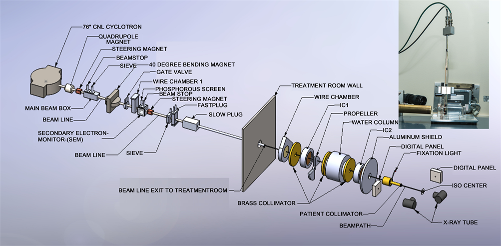
Figure 1. Layout of ocular beam line at UCSF-CNL Eye Treatment Facility. The beam, after entering the treatment room, passes through several devices before radiating the patient at the iso-center. The insert in the figure shows the experimental setup at the iso-center.
measured with wire chamber 1 (WC1), which is placed downstream of the 40-inch bending magnet. The beam size and beam position are monitored in the treatment room by wire chamber 2 (WC2). WC1 and WC2 each have 2 orthogonal planes with 2 mm and 6 mm wire spacing, respectively.
2.1. Beam Monitoring and Dosimetry System
There are three primary dose monitors. The secondary emission monitor (SEM) [17] is placed at beam stop 4 and measures the intensity of the beam. It consists of an alternating stack of high voltage foils and collection foils of aluminum. They are placed in a vacuum chamber made of stainless steel with aluminum vacuum windows. The whole chamber is placed in vacuum. The aluminum foils are held between two supporting rings of ceramic material. The SEM provides beam detection, which does not saturate at any achievable beam current. Two segmented transmission ionization chambers, IC1 and IC2 [18] [19] , define the central beam axis and provide yield information about the size and intensity of the circular field. IC1 and IC2 each have two foils, separated by a high voltage foil. One foil is divided into four quadrants, which measure the beam position (Left/Right and Up/Down) and dose. The other foil is divided into 7 rings, which give the beam width. These chambers measure the dose 1790 mm and 500 mm upstream from the iso-center. All three detectors are monitored by electronic hardware as well as by the computer. The space between IC1 and IC2 is 1290 mm. The SEM, IC1 and IC2 collect the ionization produced by the proton beam and convert it to NIM pulses with recycling integrators. These pulses are counted by preset scalers, 12-channel LeCroy scalers and Ortec scalers, and are read by the MicroVAX 3500 computer via CAMAC.
A range modulator [20] made from Lucite is located just after IC1. It is followed by a variable water column, which permits measurements to be made at various depths of penetration [21] . The water column consists of a piston in a cylinder connected to a water reservoir. The water in the path of the beam is contained between thin Lucite windows at the ends of the cylinder. The second Lucite window is connected to a movable piston. The amount of water between the windows is determined by the separation of the windows. An encoder reads the position of the windows to an accuracy of 0.1mm. A brass collimator with a circular opening of 35 mm at the center defines the beam size at WC2, IC1 and IC2. The SEM, IC1 and IC2 monitor the dose delivered to the patient. A large patient shield made of aluminum is placed between IC2 and the patient assembly. The patient assembly system consists of a patient-specific collimator made of brass, a closed-circuit TV (CCTV) system, a fixation light and an infrared light. A final patient-specific collimator, 50-mm from the iso-center, shapes the beam to a particular patient treatment field.
The chair is placed at the iso-center for final positioning. A head holder to position the patient’s head is attached to the chair. The base of the chair can be rotated through 360˚. The chair moves in three orthogonal directions. There are two x-ray tubes, one placed in the posterior direction, just behind the chair, and one in the lateral direction. There are two flat panel digital imagers [22] . The digital panel in the anterior-posterior direction is placed on the beam line at a fixed target-to-image distance of 1190 mm. It is attached to the patient assembly system. This imager is mounted on an air piston and interlocked to the X-ray unit. When making an exposure, the imager is in-line with the center of the focal spot and with the iso-center. The imager moves up and stops at the required position when the X-ray enable trigger is depressed. The imager returns to the parked position, which is outside of the radiation field when the X-ray button is released. The imager in the lateral direction is placed at a fixed target-to-image distance of 2000 mm, as shown in Figure 1.
2.2. Setup and Measurements
To check the uniformity of the treatment field, two sheets of 50 mm × 50 mm Gefchromic EBT-3 film (Radiation products Design, Inc, MN) were irradiated at a depth of 10 and 28 mm to a dose of 6 Gy. The 10 mm depth corresponds to the plateau region and 28 mm depth corresponds to the peak region of the depth dose curve. The primary dose measurement was performed by using a 0.1 cc Far-West ionization chamber in a tissue equivalent plastic at a depth corresponding to the middle of 20 mm spread-of-Bragg peak (SOBP) using ICRU protocol [23] . A Lucite block of 100 mm in thickness was used as back scattering materials. The exposed films were evaluated with a He-Ne scanning laser densitometer (Lumiscan Laser digitizer, Lumisys Inc, Sunnyvale, CA), which has a wavelength of 632.8 mm (0.1 mm spot size) and can measure optical densities up to 3.5 with a precision of ±0.001. The analysis of the results was performed on iMac computer using the public domain NIH image program ImageJ (developed at the US National Institute of Health and available on the Internet at http://rsb.info.nih.gov/nih-image).
A schematic view of the complete setup is shown in Figure 2. The central axis depth ionization measurements were performed in a water tank with dimensions 92 × 40 × 40 mm3.
Central-axis depth-ionization measurements were performed in a water tank with 0.1cc ionization chamber (Model IC-18, Far west) having walls made of Shonka A150 plastic. The water tank has a 0.13 mm thick kapton entrance window through which the proton beam was incident. In order to keep ionization chamber at one place in a vertical position and make it water proof, a thin plastic tube with tissue equivalent material was positioned in the center of the field as seen in Figure 1. The ionization chamber was always positioned in the center of the circular field of diameter 30 mm with the phantom surface at iso-center. To understand the effect of silicone oil on the physical characteristics of proton beam, three sets of measurements were made. In the first run, the Bragg-peak measurements were made in a water tank (simulating the tissue-equivalent of a normal eye). In the second run a small tank filled with silicone oil was placed
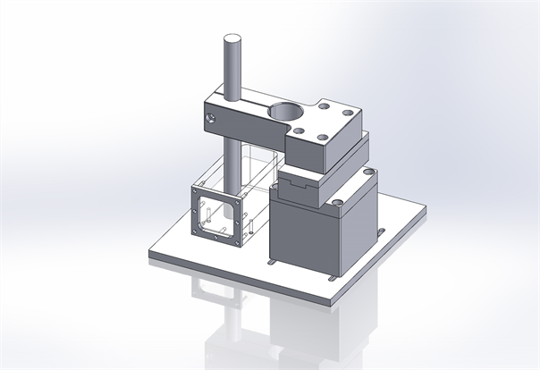
Figure 2. A schematic view of the experimental setup. The ionization chamber is placed in a thin tissue equivalent tube attached to the tank.
in front of the water tank and the measurements were repeated in water (simulating prior experiment design [15] ). In the third run the water in the tank was replaced with silicone oil and measurements repeated (simulating a silicone-filled eye). The proton beam range and physical beam characteristics were measured systematically. Finally, the effect of the change in range on dose distributions was studied based on the EYEPLAN® treatment planning software for patient cases using fundus image fusion [24] [25] .
3. Results
3.1. Proton Beam Parameters
The flatness and symmetry of the radiation field at 10 and 28 mm depth were evaluated based on International Electro Technical Commission (IEC) specifications [23] [26] . The beam flatness specifications require that the maximum distance between the 90% dose and the edge of the geometrical field shall be <10. The symmetry of the beam, measured by the difference in dose at two points symmetrically placed to the central axis, was within 1.0% at both depths. The major factor in producing excellent proton beam flatness and symmetry on this facility is that we are not using any scattering material in the beam path to produce larger field.
Figure 3 shows an example of the beam profile at 10 and 28 mm depth. The relative dose measurement (i.e. penumbra between 90% to 20%) at 10 mm and 28 mm depth shows that lateral penumbra is sharper for profile at 10 mm depth as compared to profile at 28 mm depth. The analysis of the dose uniformity shows that the dose across the beam is within ±3% at a depth of 10 mm and within ±4% at a depth of 28 mm. Table 1 shows the characteristics of the radiation field.
The measured data as shown in Figure 4 and Table 2 reveal that un-modulated
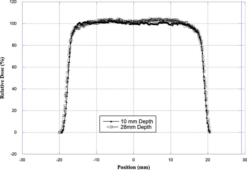
Figure 3. Comparison of the transverse dose distribution of the radiation field as measured with EBT-3 Gefchromic film. The film was placed in a plastic phantom at a depth of 10 mm and at 28 mm.
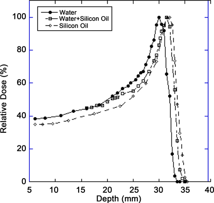
Figure 4. Comparison of the range of a 67.5 MeV proton beam in the central axis as measured in water, water + oil and in silicone oil.

Table 1. Comparison of beam profile measured with EBT-3 Gefchromic film at a depth of 10 and 28 mm.
Table 2. Comparison of Bragg peak parameters in different media.
Bragg peak has a penetration of 30 mm in water at the iso-center as compared to 32 mm range in silicone oil. By placing 1 cc of silicone oil in front of water tank, the range of proton beam is 31.5 mm. The ratio of range for water/silicone (oil +water) and water to silicone oil is 0.95 and 0.9375 respectively. The width of the depth dose curve at (FWHM) is 9 mm in water, 10 mm in water + silicone oil and 11 mm in silicone oil. The peak/plateau ratio of the depth dose is 3.1. The distal penumbra measurements (from 90% to 20%) were 1.1 mm for water, 1.4 mm for water + silicone oil and 2 mm for silicone oil, respectively.
3.2. Clinical Study for Silicone Oil Range Impact
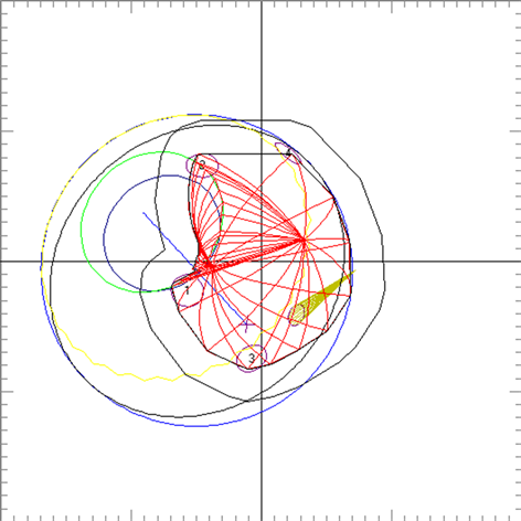
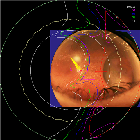
Clinical relevance of the extended distal range in silicone was studied for impact in EYEPLAN treatment planning software, including cases in which tumors were in close proximity to the optic disc/nerve and macula as well as cases in which anterior ciliary body tumors were treated. To demonstrate the necessity of the dosimetry measurement in silicone oil, we present an example of a patient with a ciliary body tumor in the right eye that is relatively amelanotic and involves the iris root but does not involve the angle. The dimension of the tumor is 13 × 8 × 8.7 mm3 (tumor height of 8.7 mm). Figure 5(a) shows the beam’s-eye-view (BEV) of the treatment plan, using gaze direction having polar and azimuth angle of (30˚, 135˚). The patient is looking towards the upper right-hand corner of the box (up and out). The range of the beam is 14.7 mm and SOBP is 16 mm. The aperture contour around the tumor represents the 50% isodose line. The optic nerve and macula are behind the tumor and receiving no proton dose, while some portion of the lens is within the 50% isodose line. This can be clearly seen from Figure 5(b) which shows the treatment plan in the lateral view. Figure 6(a) shows the dose distribution in the fundus view for a normal eye and figure 6(b) shows the dose distribution in the fundus view for a silicone oil filled eye, with adjusted proton range. Figure 7(a) and Figure 7(b) are the respective dose volume histograms (DVHs) for the two scenarios of a normal water-equivalent eye (7a) and a silicone-filled eye with potential proton range impact (7b). In this case as seen from Figure 6(a) and Figure 7(a), optic disc, macula and optic nerve gets 0 dose in the normal eye. If the eye were to be filled with silicone oil, the range of the beam would increase by 2mm. In that case as seen from Figure 6(b) and Figure 7(b), the dose to 50% area of the disc would increase by 50% of the total dose (i.e. 28 GyE in this simulation). A length of 0.4 mm of the optic nerve would receive 50% of the total dose (Figure 7(b)) as compared to the treatment plan if the eye is filled with water (Figure 7(a)). The doses to the structures of the eye in two scenarios are summarized in Table 3.
 (a)
(a)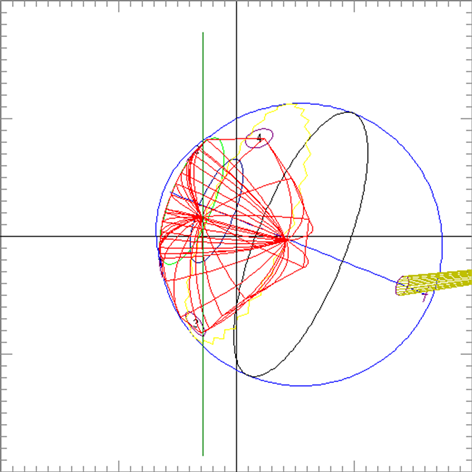 (b)
(b)
Figure 5. (a) The illustration of the treatment of uveal melanoma of the right eye in beam’s-eye-view using gaze direction having polar and azimuth angle of (30˚, 135˚). The patient is looking towards the upper right-hand corner of the box (up and out). The aperture contour around the tumor represents the 50% isodose line. The optic nerve and macula are posterior to the tumor, while a portion of the lens is in the field. (b) Shows the treatment plan in the transverse plane. The optic nerve and macula are estimated at 7 mm and 10 mm from the tumor.
 (a)
(a) (b)
(b)
Figure 6. The isodose lines are displayed on the polar view of the back of the eye. The fundus image is superimposed on the polar view. The macula lies at the center of this view (represented by a cross), and the rest of the eye is “unfolded” around it. The optic nerve and disc are also shown near the center of the eye. The concentric circles represent the equator, ora serrata, lens and limbus of the cornea (moving from the back to the front of the eye). (a) dose distribution for normal eye (b) for eye filled with silicone oil.
4. Discussion
In many centers, proton beam therapy is the first choice of treatment of uveal melanoma with excellent local control [1] - [6] . Accurate planning and delivery of the treatment are of utmost importance in maintaining a high success rate. As

Figure 7. Cumulative (integral) dose-volume histogram showing the dose to various structures of the eye for (a) normal eye and (b) eye filled with silicone oil. The optic disc and optic nerve dose is elevated in the silicone filled eye due to the change in range of proton beam.
Table 3. Dose to various structures of the eye in two scenarios (i.e. normal eye and the same eye but filled with silicone oil).
new proton facilities along with new surgeons, radiation oncologist and physicists arise to treat this rare disease it becomes even more important to delineate and standardize approaches to potential impact on beam parameters with ocular intervention. In this paper, we have studied the essential parameters of range and beam characteristics for a proton beam in ocular patients who present with silicone-filled eyes.
Silicone oil tamponade for retinal detachment is widely used [9] [10] [11] [12] [13] . Previously, Weber et al. [15] studied the change in proton range in eyes with clinical silicone oil tamponade and showed that by placing silicone oil in front of a water tank, that range of proton beam increased by 11%. Their experimental measurements were made in water and the effect of silicone oil was studied by placing silicone oil in a small tank in front of the water tank. These measurements showed the effect on proton range.
In our paper we build on this initial work to provide a comprehensive description of the effect of silicone oil on proton beam parameters, particularly with an experimental design to more closely simulate an eye filled with silicone. Thus, we made the measurements of our proton beam in a tank of silicone oil itself (simulating a silicone-filled eye) and compared the beam parameters to that in a water tank (simulating a “normal” eye) as well as water + silicone oil as previously described. The results indicate that the shape of the Bragg-peak is affected in silicone oil and range of the beam is increased by 2 mm in silicone oil and 1.5 mm in water + silicone oil. This is congruent with initial results from Weber et al. [15] . The width of the depth dose curve at (FWHM) is 9 mm in water, 10 mm in water + silicone oil and 11 mm in silicone oil. The distal penumbra measurements (90% to 20%) are 1.1 mm for water, 1.4 mm for water + silicone oil and 2 mm for silicone oil, respectively.
The potential adjustments to distal range and penumbra in the context of silicone oil filled eyes are important for clinical eye treatment planning. The ocular melanoma case example presented in this study demonstrates that for example eyes with a thick ciliary body tumor may appear to receive zero dose to the optic nerve and disc. However once planning model modifications are made to reflect the potential impact of silicone oil on the range of the proton beam, the disc and nerve dose increase. In the silicone oil modified plan of the same eye, 50% of the area of the disc would receive 50% of the total dose and a length of 0.4 mm of the optic nerve would receive 50% of the total dose. Such clinically relevant information is essential for treatment planning, dose volume analysis, and informing the clinician and patient.
5. Conclusion
The use of silicone oil as a surgical tamponade in the treatment of retinal detachment has important implications for PBRT treatment planning. In patients with intraocular silicone, the physical parameters of the beam should be closely examined and DVHs particularly for posterior structures should be analyzed for potential increased doses to the macula, disc, and length of optic nerve in the field. The change in beam parameters caused by silicone oil is essential to consider in treatment planning and DVH interpretation for ocular patients with posterior as well as anterior ocular tumors.
Acknowledgements
We would like to extend our thanks to the Director of Crocker Nuclear Laboratory and his staff for his continued interest and support of proton therapy. The authors gratefully acknowledge the excellent technical support by Brian Devine of CNL in designing the water tank and other phantom materials during the progress of experiment. Our thanks go to Randy Kemmler for his technical support during the treatment of patients.
Conflict of Interest
The authors have no conflict of interest.
Cite this paper
Daftari, I.K., Mishra, K.K., Seider, M. and Damato, B.E. (2018) Proton Beam Ocular Treatment in Eyes with Intraocular Silicone Oil: Effects on Physical Beam Parameters and Clinical Relevance of Silicone Oil in EYEPLAN Dose-Volume Histograms. International Journal of Medical Physics, Clinical Engineering and Radiation Oncology, 7, 347-362. https://doi.org/10.4236/ijmpcero.2018.73029
References
- 1. Castro, J.R., Char, D.H., Patti, P.L., Daftari, I.K., Quivey, J.M., Singh, R.P., Blakely, E.A. and Phillips, T.L. (1997) 15 Years Experience with Helium Ion Radiotherapy for Uveal Melanoma. International Journal of Radiation Oncology · Biology · Physics, 39, 989-996. https://doi.org/10.1016/S0360-3016(97)00494-X
- 2. Gragoudas, E.S., Egan, K.M., Seddon, J.M., Walsh, S.M. and Munzenrider, J.E. (1992) Intraocular Recurrence of Uveal Melanoma after Proton-Beam Therapy Ophthalmology, 99, 760-766. https://doi.org/10.1016/S0161-6420(92)31900-1
- 3. Egger, E., Schalenbourg, A., Zografos, L., Bercher, L., Boehringer, T., Chamot, L. and Goitein, G. (2001) Maximizing Local Tumor Control and Survival after Proton Beam Radiotherapy of Uveal Melanoma. International Journal of Radiation Oncology · Biology · Physics, 51, 138-147. https://doi.org/10.1016/S0360-3016(01)01560-7
- 4. Damato, B., Kacperek, A., Chopra, M., Campbell, I.R. and Errington, R.D. (2005) Proton Beam Radiotherapy of Choroidal Melanoma: The Liverpool-Clatterbridge Experience. International Journal of Radiation Oncology · Biology · Physics, 62, 1405-1411. https://doi.org/10.1016/j.ijrobp.2005.01.016
- 5. Hirasawa, N., Hiroshi, T., Ishikawa, H., Koyama-Ito, H., Kamada, T., Mizoe, J., Ito, Y., Naganawa, S., Ohnishi, Y. and Sujii, H. (2007) Risk Factors for Neovascular Glaucoma after Carbon Ion Radiotherapy of Choroidal Melanoma Using Dose-Volume Histogram Analysis. International Journal of Radiation Oncology · Biology · Physics, 67, 538-543. https://doi.org/10.1016/j.ijrobp.2006.08.080
- 6. Daftari, I.K., Petti, P.L., Shrieve, D.C. and Phillips, T.L. (2006) Newer Radiation Modalities for Choroidal Tumors. International Ophthalmology Clinics, 46, 69-79.https://doi.org/10.1097/01.iio.0000195863.79181.4f
- 7. Mishra, K.K., Quivey, J.M., Daftari, I.K., Weinberg, V., Cole, T.B., Patel, K., Castro, J.R., Phillips, T.L. and Char, D.H. (2015) Long-Term Results of the UCSF-LBNL Randomized Trial: Charged Particle with Helium Ion versus Iodine-125 Plaque Therapy for Choroidal and Ciliary Body Melanoma International Journal of Radiation Oncology · Biology · Physics, 92, 376-383.https://doi.org/10.1016/j.ijrobp.2015.01.029
- 8. Kivela, T., Eskelin, S., Makitie, T. and Summanen, P. (2001) Exudative Retinal Detachment from Malignant Uveal Melanoma: Predictors and Prognostic Significance. Investigative Ophthalmology & Visual Science, 42, 2085-2093.
- 9. Azen, S.P., Scott, I.U., Flynn, H.W., Lai, M.Y., Topping, T.M., Benati, L., Trask, D.K. and Rogus, L.A. (1998) Silicone Oil in the Repair of Complex Retinal Detachment; a Prospective Observational Multicenter Study. Ophthalmology, 105, 1587-1597. https://doi.org/10.1016/S0161-6420(98)99023-6
- 10. Konstantinidis, L., Groenewald, C., Coupland, S.E. and Damato, B. (2014) Long-Term Outcome of Primary Endoresection of Choroidal Melanoma. British Journal of Ophthalmology, 98, 82-85. https://doi.org/10.1136/bjophthalmol-2013-304022
- 11. Beykin, G., Pe’er, J., Hemo, Y., Frenkel, S. and Chowers, I. (2013) Pars Plana Vitrectomy to Repair Retinal Detachment Following Brachytherapy for Uveal Melanoma. British Journal of Ophthalmology, 97, 1534-1537.
- 12. Haimovici, R., Mukai, S., Schachat, A.P., Haynie, G.D., Thomas, M.A., Mrredith, T.A. and Gragoudas, E.S. (1996) Rhegmatogenous Retinal Detachment in Eyes with Uveal Melanoma. Retina, 16, 488-496. https://doi.org/10.1097/00006982-199616060-00004
- 13. McCannel, T.A. and McCannel, C.A. (2014) Iodine 125 Brachytherapy with Vitrectomy and Silicone Oil in the Treatment of Uveal Melanoma: 1-to-1 Matched Case-Control Series. International Journal of Radiation Oncology · Biology · Physics, 89, 347-352. https://doi.org/10.1016/j.ijrobp.2014.02.021
- 14. Ahuja, Y., Kapoor, K.G., Thomson, R.M., Furutani, K.M., Shulz, R.W., Stafford, S.L., Dev, S., Abu-Yaghi, N.E., Reynolds, D. and Pulido, J.S. (2012) The Effect of Intraocular Silicone Oil Placement Prior to Iodine 125 Brachytherapy for Uveal Melanoma: A Clinical Case Series. Eye, 26, 1487-1489. https://doi.org/10.1038/eye.2012.158
- 15. Weber, A., Cordini, D., Stark, R. and Heufelder, J. (2012) The Influence of Silicone Oil Used in Ophthalmology on the Proton Therapy of Uveal Melanomas. Physics in Medicine & Biology, 57, 8325-8341. https://doi.org/10.1088/0031-9155/57/24/8325
- 16. Daftari, I.K., Renner, T.R., Verhey, L.J., Singh, R.P., Nyman, M., Petti, P.L. and Castro, J.R. (1996) New UCSF Proton Ocular Beam Facility at the Crocker Nuclear Laboratory Cyclotron (UC Davis). Nuclear Instruments and Methods in Physics Research Section A, 380, 597-612.
- 17. Taufest, G.W. and Fechter, H.R. (1955) Non Saturable High-Energy Beam Monitor. Review of Scientific Instruments, 26, 229-231. https://doi.org/10.1063/1.1771258
- 18. Lyman, J.T., Howard, J. and Windsor, A. (1975) Heavy Charged Particle Beam Monitoring with Segmented Ionization Chambers. Medical Physics, 2, 163.
- 19. Chu, W.T., Ludewight, B.A. and Renner, T.R. (1993) Instrumentation for Treatment of Cancer Using Proton and Light Ion Beams. Review of Scientific Instruments, 64, 2055-2122. https://doi.org/10.1063/1.1143946
- 20. Petti, P.L., Lyman, J.T., Renner, T.R., Castro, J.R., Collier, J.M., Daftari, I.K. and Ludewight, B.A. (1991) Design of Beam-Modulating Devices for Charged-Particle Therapy. Medical Physics, 18, 513-518. https://doi.org/10.1118/1.596655
- 21. Tobias, C.A., Lyman, J.T., Chatterji, A., Howard, J., Maccabee, H.D., Raju, M.R., Smith, A.R., Sperinde, J.M. and Welch, G.P. (1971) Radiological Physics Characteristics of Extracted Heavy Ion Beams of Bevatron. Science, 174, 1131-1134.
- 22. Daftari, I.K., Essert, T. and Phillips, T.L. (2009) Application of Flat Panel Digital Imaging for Improvement of Ocular Melanoma Patient Set-Up in Proton Beam Therapy. Nuclear Instruments and Methods in Physics Research Section A, 598, 628-634.
- 23. International Commission on Radiation Units and Measurements (ICRU) (1998) Clinical Proton Dosimetry Part I: Beam Production, Beam Delivery and Measurement of Absorbed Dose ICRU59.
- 24. Goitein, M. and Miller, T. (1983) Planning Proton Therapy of the Eye. Medical Physics, 10, 275-283. https://doi.org/10.1118/1.595258
- 25. Daftari, I.K., Mishra, K.K., O’Brien, J.M., Tsai, T., Park, S.S., Sheen, M. and Phillips, T.L. (2010) Fundus Image Fusion in EYEPLAN Software: An Evaluation of a Novel Technique for Ocular Melanoma Radiation Treatment Planning. Medical Physics, 37, 5199-5207. https://doi.org/10.1118/1.3488891
- 26. International Electrotechnical Commission (IEC) (1984) Medical Electrical Equipment, Medical Electron Accelerators, Section IV: Functional Performance Characteristics and Report IEC Report 35-I and 35-II.