Open Journal of Civil Engineering
Vol.06 No.02(2016), Article ID:64483,17 pages
10.4236/ojce.2016.62013
Optimum Design of Tied Back Retaining Wall
Nabeel A. Jasim, Ahmed M. Al-Yaqoobi
Department of Civil Engineering, College of Engineering, University of Basra, Basra, Iraq

Copyright © 2016 by authors and Scientific Research Publishing Inc.
This work is licensed under the Creative Commons Attribution International License (CC BY).
http://creativecommons.org/licenses/by/4.0/


Received 25 August 2015; accepted 11 March 2016; published 14 March 2016
ABSTRACT
This paper presents an optimization algorithm for the design of tied back retaining wall which is comprised of the same three basic elements: stem, toe and heel, where the stem is hinged to the base and tied to the heel by multiple tie rods at intervals along the wall. The aim of this study is to find the values of design variables for this suggested type of tied back retaining walls which minimize the cost function subjected to constraints of the problem. The optimum design of such structure is conducted by using one of the nontraditional optimization methods, genetic algorithm (GA). The formulation of the problem is based on the elastic analysis and the ultimate strength method of design as per ACI-318-2011 code. The built-in genetic algorithm optimtool of Matlab program is utilized to optimize the cost function of the wall. The cost of concrete, reinforcing steel, tie steel, formwork, excavation, and backfilling works are included. The considered design variables are the geometric dimensions and the amounts of reinforcement for the base slab and stem slab, as well as the amount of tie steel. The developed program is utilized to perform an extensive parametric study regarding the height of wall, backfill soil properties, and materials properties including concrete, reinforcing steel, and tie steel. The backfill properties are represented by a pressure coefficient, which is a function of the unit weight and the angle of internal friction. Average expressions are calculated for the total cost and optimum dimensions as ratios of the wall height H2 which may be useful for the practical design of walls.
Keywords:
Retaining Walls, Tied Back Wall, Optimization, Optimtool, Genetic Algorithm

1. Introduction
In design process, engineers have to take many technological and managerial decisions at several stages. The present design of economical concrete structures mainly follows rules based on the experience of structural engineers. Most procedures adopt the cross-section dimensions and material grades sanctioned by common practice. Structural optimization methods are clear alternatives to designs based on experience. Optimum design is a structural synthesis which collects all important engineering aspects to develop structural versions not only safe but also economic. The economy is achieved by minimizing a cost function and the safety is guaranteed by fulfilling the design constraints.
The constraints may be based on stability, bending moment and shear force capacities, and some of the other measures. Thus, the problem can be defined mathematically as a constrained function minimization task, which may be solved by a mathematical programming method [1] .
The improvements in numerical methods and computer technology have given impetus to this concept of optimization. In recent years, some optimization methods that are conceptually different from the traditional mathematical programming techniques have been developed. These methods are labeled as modern or nontraditional methods of optimization. Most of these methods are based on certain characteristics and behavior of biological, molecular, swarm of insects, and neurobiological systems.
Several authors have surveyed the utilization of optimization in structural design. Al-Janabi [2] (1983) studied the structural behavior of a proposed L-shape tied-back type of retaining walls. The finite element method was utilized to perform the calculations necessary to construct design curves for tie positions, which gives minimum values of bending moments. It should be pointed out that the study did not use any mathematical programming technique, but merely used the graphical representation of the results. Ceranic and Fryer [3] (1999) presented results of the application of a constrained simulated annealing algorithm to the minimum cost design of reinforced concrete cantilever retaining walls. A modified simulated annealing algorithm was proposed that avoids the simple rejection of infeasible solutions and improves convergence to a minimum cost. Results obtained so far have shown that simulated annealing can be successfully applied to the minimum cost design of reinforced concrete retaining walls. M. Ghazavi and A. Heidarpour [4] (2003) presented an optimization algorithm for the design of reinforced concrete counter fort retaining walls. A special efficient computer program was developed for this purpose. For the analysis of lateral earth pressures on the wall, the well known Coulomb, Rankine, and wedge methods were used. The backfill was treated as homogeneous or stratified also horizontal or inclined. The effects of surcharge, hydrostatic water pressure, seepage water pressure, and seismic loading on the lateral earth pressure were incorporated. Input parameters were generally the height of the wall, backfill slope, and backfill and base soil geotechnical parameters. Appropriate strengths for concrete and steel were introduced to the optimization scheme. Structural stability due to bending moment and shear force, geotechnical considerations such as sliding, overturning, settlement and bearing capacity were taken into account. The costs of construction material mainly concrete, reinforcing steel, and formwork had been considered for various acceptable materials. In the analysis, the geometry of the wall was optimized and compared with the recommended values. It was shown that the optimization of counter fort retaining walls can reduce the costs involved. Yepes et al. [5] (2007) examined the economic optimization of reinforced concrete earth-retaining walls used in road construction. The simulated annealing algorithm was the proposed method to optimize walls. The formulation of the problem included 20 design variables: four geometrical ones dealing with the thickness of the kerb and the footing, as well as the toe and the heel lengths; four material types; and 12 variables for the reinforcement set-up. The study estimated the relative importance of factors such as the base friction coefficient, the wall-fill friction angle and the limitation of kerb deflections. Finally, the paper presented a parametric study of commonly used walls from 4 to 10 m in height for different fills and bearing conditions. Average expressions were calculated for the total cost, the volume of concrete, the thickness of the kerb and the footing, the lengths of the footing and the heel, which may be useful for the practical design of walls. An upper bound of 50 kg/m3 of reinforcement in the kerb and 60 kg/m3 for the overall wall was reported. Magbo et al. [6] (2012) generated a design curves for optimal design of an anchored sheet pile wall in cohesionless soils based on the results of geotechnical investigation of soil at six different sites using free earth support approach. It was shown that the penetration depth decreased with the increase in angle of internal friction. The tension force in the anchor was also found to increase with the increase in angle of internal friction up to a maximum value of about 250 kN/m which corresponds to an optimum value of angle of internal friction of about 25˚. The design curves had showed the efficiency of the optimum design of an anchored sheet pile wall, the values of the design parameter may vary if the free wall height exceeds 7.5 m used in the study. Sable and Patil [7] (2012) developed a program for the analysis and design of low-cost or low-weight cantilever reinforced concrete retaining walls with and without base shear key using Matlab optimtool. The comparison between the conventional design from known designer and optimum cost and weight values which were observed from optimtool showed effectively by cost and weight minimization model and graph. As per conventional design, cost can be reduced by optimization 15% to 30% and weight by 33% to 38% for cantilever retaining wall of height 3 to 6.5 m.
In this research work, a new type of retaining walls is considered. It is comprised of the same three basic elements: stem, toe and heel, where the stem is hinged to the base and tied to the heel by multiple tie rods at intervals along the wall. The tied back retaining wall is suggested to consist of a precast stem of high heights and the base is cast in situ.
2. Optimization Scheme
Optimization is the act of obtaining the best result under given circumstances [1] . There are many methods that are used to solve the optimization problems [8] . In recent years, some optimization methods that are conceptually different from the traditional mathematical programming techniques have been developed. These methods are labeled as modern or nontraditional methods of optimization. Most of these methods are based on certain characteristics and behavior of biological, molecular, swarm of insects, and neurobiological systems.
One of these modern methods is the genetic algorithm (GA) method (John Holland, 1975) which has been utilized to analyze tied back retaining walls. Genetic algorithms are stochastic search methods that mimic some of the processes of natural biological evolution [9] . The primary purpose of using genetic algorithms is optimization. Genetic algorithms operate on a population of potential solutions applying the principle of “survival of the fittest” to produce better approximations to a solution. Genetic algorithms model natural processes [9] , such as selection, recombination, and mutation.
The stages of the optimization scheme consist of consideration of structural stability, general stability, geotechnical stability, and costs. The required parameters are given subsequently.
3. Formulation for Optimal Design
In optimal design problem of retaining wall the aim is to minimize the construction cost of the wall under constraints. This optimization problem can be expressed as follows:
Minimize f(X) which is subject to
 (1)
(1)
 (2)
(2)
 (3)
(3)
where X is n-dimensional vector called the design vector,  is the objective function, and
  and
and  are inequality and equality constraints respectively and
 ,
,  are lower and upper bound constraints. To economic design of retaining wall, the objective function, design variables and design constraints should be defined explicitly.
3.1. Input Parameters
For the analysis of wall, the geometry of the tied back wall can generally be described by a set of quantities, some of which are viewed as variables during the optimization process. Some quantities are fixed during the process and called “pre-assigned parameters”. These are outlined as:
・ The properties of backfill and base soil.
・ Height of tied back retaining wall.
・ Unit weight of concrete, steel and soil.
・ The minimum cover for the reinforcement of stem and base.
・ The compressive strength of the concrete and the yield strength of the steel to be used in the design.
・ The allowable tensile stress of tie steel.
・ The cost of each concrete, reinforcing steel, tie steel, formwork, excavation and backfilling works.
・ Strength reduction factor ( ).
).
3.2. Design Variables
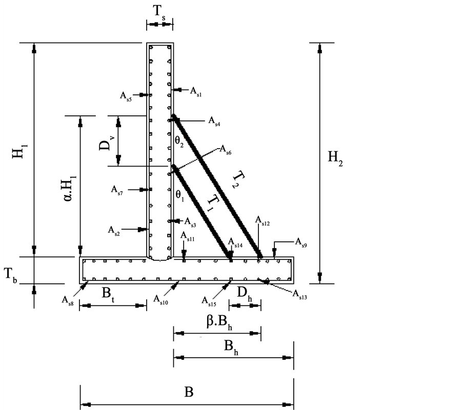
The design variables are divided into two categories: those that prescribe the geometric dimensions of wall cross-section, and those that model the steel reinforcement. In general, there are nine design variables of the geometric dimensions to be optimized as shown in Figure 1: Ts: thickness of stem, Tb: thickness of base, Bt: length of toe, Bh: length of heel, Dv: vertical distance between ties, Dh: horizontal distance between ties, α: ratio of height of top of outer tie to wall height (H1), β: ratio of horizontal distance of outer tie to length of heel (Bh), S: tie spacing.
Whereas the steel reinforcement design variables are modeled as a set of discrete values and include: At1, At2: the area of outer and inner tie section respectively, As1: the area of vertical reinforcement at the stem for negative bending moment (active face of wall), As2: the area of vertical reinforcement at the stem for positive bending moment (passive face of wall), As3: the area of longitudinal reinforcement at the stem in the two faces for temperature and shrinkage, As4, As5: the area of longitudinal reinforcement at the outer tie level in the stem at tie point and between ties respectively, As6, As7: the area of longitudinal reinforcement at the inner tie level in the stem at tie point and between ties respectively, As8: the area of main reinforcement at the bottom of the toe, As9: the area of main reinforcement for negative bending moment at the heel, As10: the area of main reinforcement for positive bending moment at the heel, As11: the area of longitudinal reinforcement at the base in the two faces for temperature and shrinkage, As12, As13: the area of longitudinal reinforcement at the outer tie in the heel at tie point and between ties respectively, As14, As15: the area of horizontal reinforcement at the inner tie level in the
Figure 1. Design variables for typical reinforced concrete tied back retaining wall.
base at tie point and between ties respectively.
3.3. Design Constraints
The typical design philosophy for retaining structures seeks designs that provide safety and stability against failure modes and comply with concrete building code requirements. These requirements may be classified into two groups of constraints namely, the general constraints and the ultimate resistance constraints. Within the optimization procedure, if all considered constraints and cost considerations are entirely met, the design will be feasible. These requirements represent the failure modes as a function of the design variables. Failures modes are summarized in Table 1.
Some constraints have maximum allowable value much larger than that of other constraints. This will badly affect the convergence rate during the minimization of cost function. Therefore, normalization is used which gives after rearranging the equations of these constraints.
3.3.1. Sliding Failure Mode
The net horizontal forces must be such that the wall is prevented from sliding along its foundation. The most significant sliding force component usually comes from the lateral earth pressure acting on the active (backfill) side of the wall. Sliding failure is a result of excessive lateral earth pressures with relation to retaining wall resistance thereby causing the retaining wall system to move away (slide) from the soil it retains.
 (4)
(4)
where : friction force,
 : passive force,
 : driving force,
 : 1.25 to 2 depending on the importance of the wall, say 1.5 as recommended by Bowles for retaining walls structures [10] .
3.3.2. Overturning Failure Mode
The stabilizing moments, due to vertical forces must be greater than the overturning moments, due to horizontal forces to prevent rotation of the wall around its toe. The stabilizing moments result mainly from the self-weight of the structure, whereas the main source of overturning moments is the active earth pressure. Overturning failure is a result of excessive lateral earth pressures with relation to retaining wall resistance thereby causing the retaining wall system to topple or rotate (overturn).

where


3.3.3. Excessive High Toe Pressure
To avoid excessive high toe pressure it is desirable to keep the resultant of the various forces acting on the wall
Table 1. Failures modes of the problem.
R within the middle third of the base, so that no tension is developed at the base [10] .


where B: base width,
3.3.4. Bearing Capacity
The bearing capacity of the foundation must be large enough to resist the stresses acting along the base of the structure.

where


3.3.5. Moment Failure Mode
The maximum bending moments at the critical sections should be less than the resistance moments for both stem and base.

where


i = index indicating the critical sections of toe, heel and stem,


Figure 2. Equivalent rectangular stress block.
3.3.6. Minimum Area of Reinforcement Criteria
The reinforcement area for bending moment at any section where tensile reinforcement is required should not be less than (

where (

3.3.7. Tension Controlled Sections
Sections are tension-controlled if the net tensile strain in the extreme tensile steel (

where 
3.3.8. Shear Failure Mode
The available effective depth must be greater than that required for wide beam shear requirement [11] . So the effective depth for both stem and base must checked as follows,


where S: distance between ties,


3.4. Objective Function
The objective function is a function of design variables the value of which provides the basis for choice between alternate acceptable designs. The objective of design may be minimization of weight, cost or stress concentration factor. In structural designs the objective function is usually weight or cost minimization.
In the present study, the objective function is defined as the total cost of tied back retaining wall (material and labor) for a spacing length (S) of the wall. This includes the cost of concrete


where


4. Application of Developed Program
The applications in this section involve solving many numerical examples in order to illustrate the effects of various design variables and different parameters on the optimal design. The minimum cost of the tied back retaining wall for a distance equal to the spacing between ties (S) is given. These examples are concerned with the following points:
・ The effect of the total height of the tied back retaining wall.
・ The effect of pressure coefficient, K, which is a function of backfill properties, i.e.
・ The effect of materials properties (concrete, reinforcing steel, and tie steel).
The program consists of two main stages. In the first stage the necessary data are specified. The second stage performs the calculations of the optimum design.
4.1. Effect of the Total Height of Wall
To investigate the effect of the total height of the tied back retaining wall, height equal to (6, 7, 8, 9 and 10) m is used. The basic values of required parameters are taken as pressure coefficient K = 6 kN/m3, yield stress of steel fy = 276 MPa, concrete cylinder compressive strength
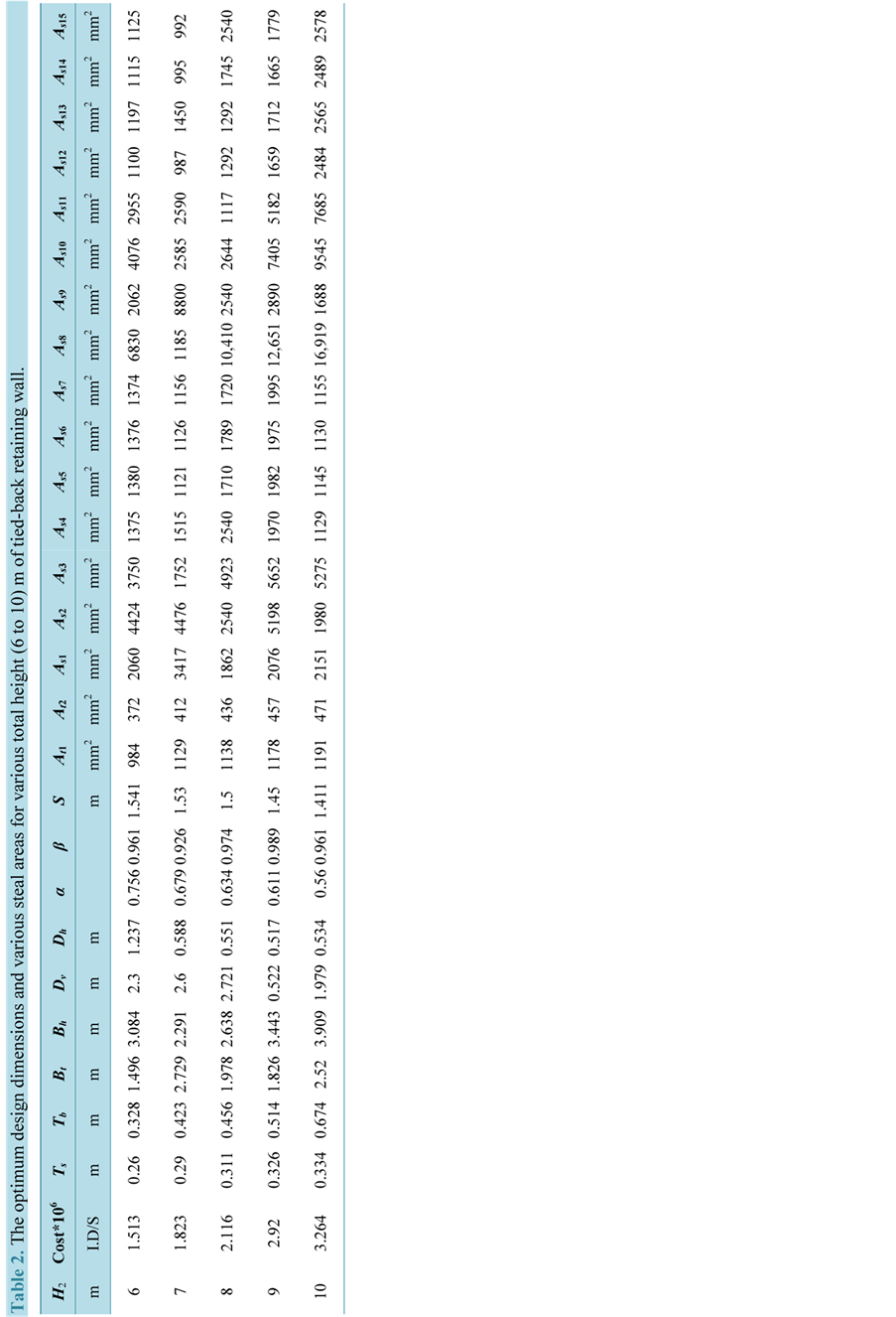
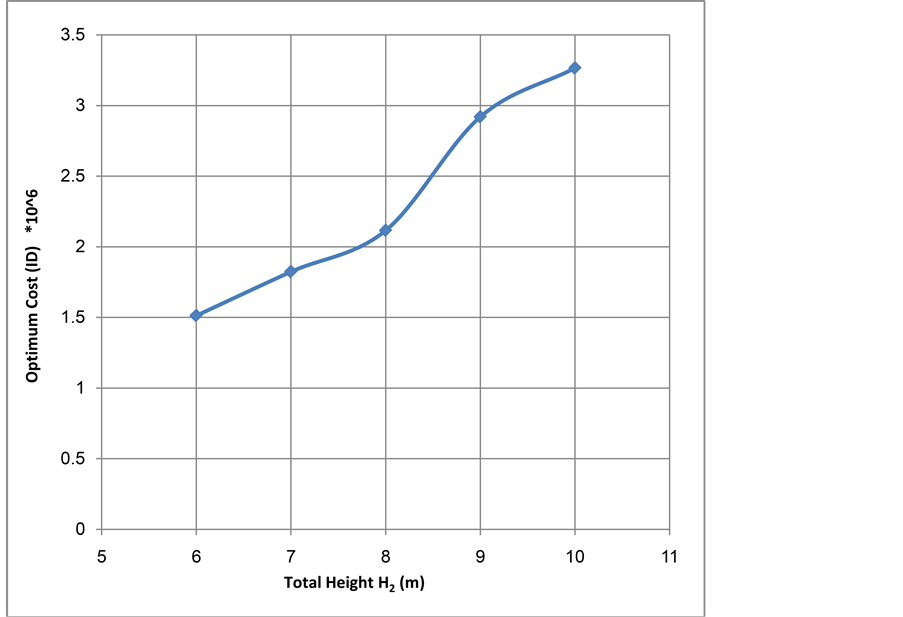
The optimal solution has been summarized in Table 2 and Figure 3 in which the height represents the total height of tied back retaining wall H2.
It can be noticed from this table and figure that the total cost of wall increases as the total height H2 increases. The data from this table and figure also shows nonlinear relationship between the total cost of wall and the total height H2. This relation usually depends on many factors like material properties and the different unit prices as will be discussed in following sections. The total height of tied back retaining wall has affected on the optimum stem thickness Ts which increases with the increase of total height H2. Also the thickness of the base Tb increases as the wall height increases.
4.2. The Effect of Pressure Coefficient
In order to examine the effect of backfill properties 
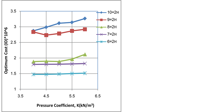
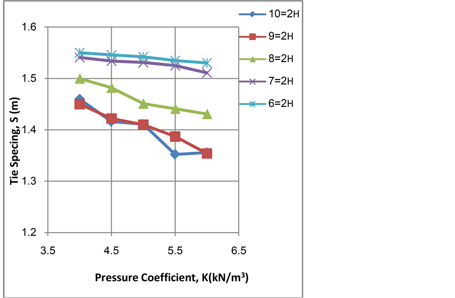
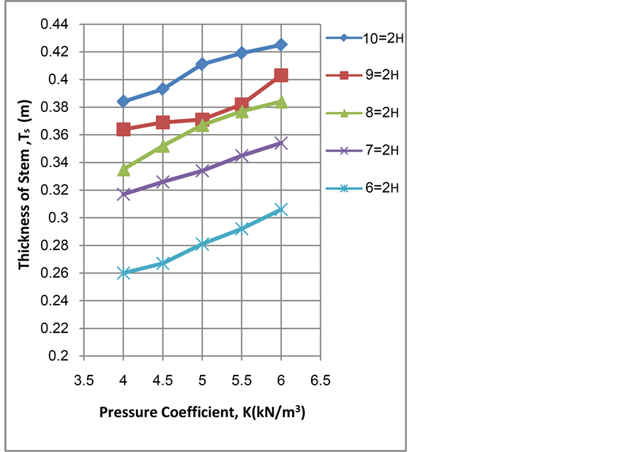
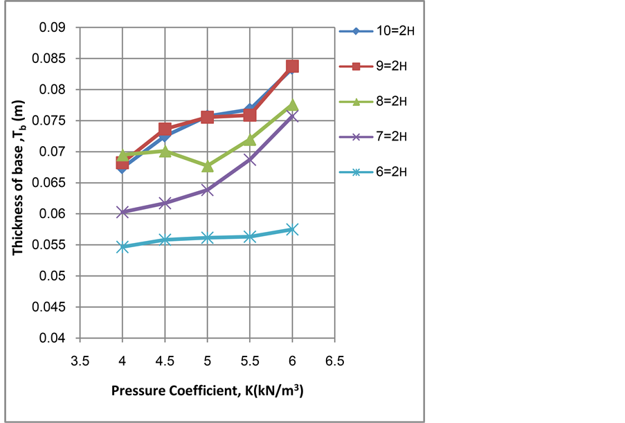
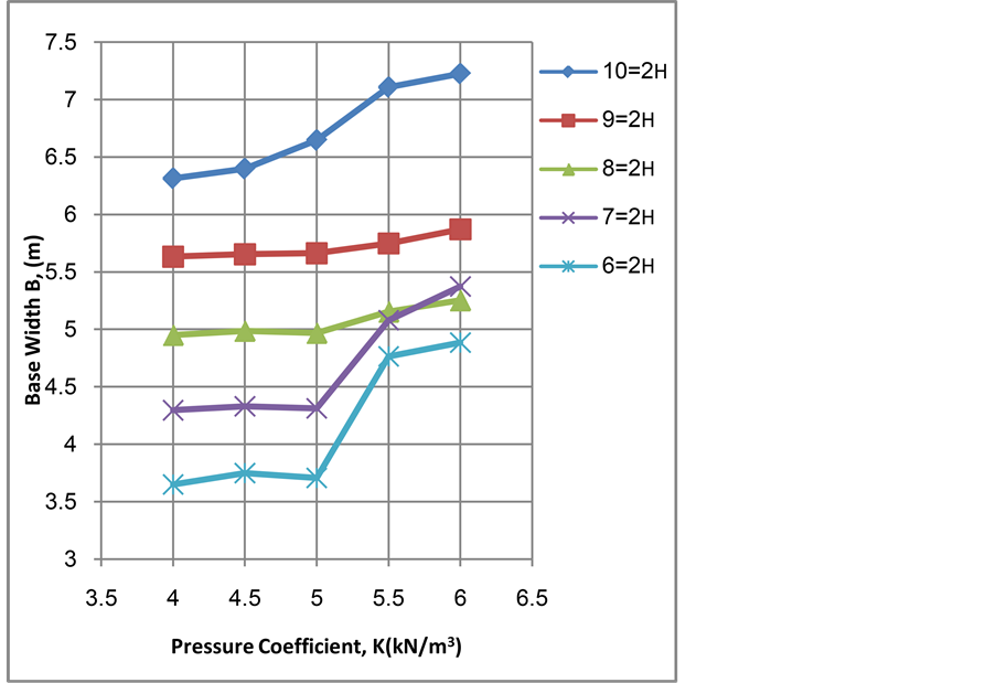
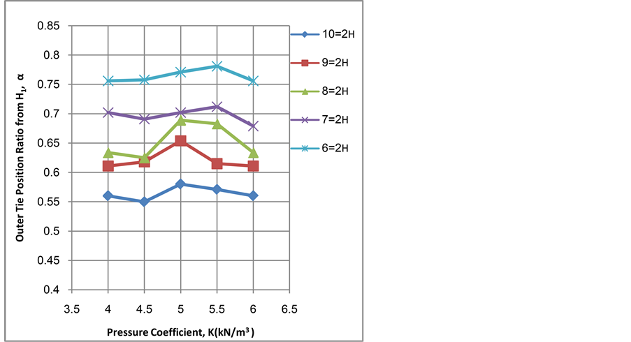
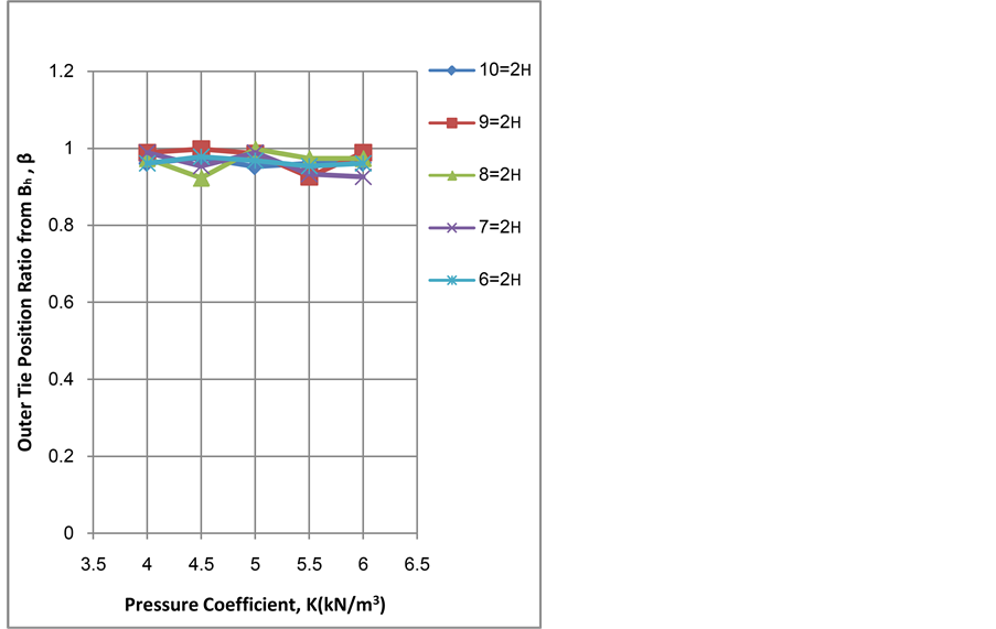
It is clear from Figure 4 that the minimum cost increases according to the increase of wall height. The influence of pressure coefficient increases as the wall becomes higher. From Figure 5 it is clear that the tie spacing is inversely proportional to wall height and it can be noticed that the effect of pressure coefficient vanishes as the wall becomes higher. It is clear from Figure 6 that the stem thickness increases according to the increase of wall height. The increasing of pressure coefficient leads to increase the stem thickness in same rate as the wall becomes higher. From Figure 7, it is clear that the base thickness increases with the increase of wall height. Also it can be noticed, in general, that increasing pressure coefficient seems to have little effect on base thickness up to 5 kN/m3 and the effect appears after that. It can be seen that the effect of height vanishes for wall heights 9 m and 10 m where the curves coincide. It can be realized from Figure 8 that the base width is proportional to wall height. Also there is no effect of pressure coefficient up to 5 kN/m3 and after that the influence of pressure coefficient is increasing obviously. It is clear from Figure 9 that the outer tie position ratio from H1, α, is inversely proportional to wall height and it seems not to alter as the pressure coefficient varies. It is clear from Figure 10 that the increase in wall height and pressure coefficient has a very little effect on the outer tie position ratio from Bh, β, it seems to be constant, about (0.92 to 1) times Bh.
4.3. The Effect of Materials Properties
The properties of concrete, reinforcing steel, and tie steel play an important role on the optimum design. Their effects have arisen not only in unit price of each material but also in their specifications that influence the optimal design as will be shown in this section.
In order to examine the effect of concrete compressive strength on the optimum results different grades of concrete are considered. Grades (25, 30, 40, and 50 MPa), which indicate the cylinder compressive strength, are
Table 2. The optimum design dimensions and various steal areas for various total height (6 to 10)m of tied-back retaining wall.
investigated. The remaining parameters are considered to have the same values of Section 4.1. Since practically the increase in grade of concrete leads to increase its cost, so the effect of unit cost of concrete is combined with the influence of concrete compressive strength here. The unit costs of concrete considered in this study for the specified compressive strengths (25, 30, 40, and 50 MPa) are (150,000, 250,000, 500,000, 700,000) I.D/m3 respectively.
Figure 3. Optimum cost versus total wall height, H2.
Figure 4. Optimum cost versus pressure coefficient, K, for different values of wall height, H2.
Figure 5. Tie spacing, S, versus pressure coefficient, K, for different values of wall height, H2.
Figure 6. Stem thickness, Ts, versus pressure coefficient, K, for different values of wall height, H2.
Figure 7. Base thickness, Tb, versus pressure coefficient, K, for different values of wall height, H2.
Figure 8. Base width, B, versus pressure coefficient, K, for different values of wall height, H2.
Figure 9. Outer tie position ratio from H1, α, versus pressure coefficient, K, for different values of wall height, H2.
Figure 10. Outer tie position ratio from Bh, β, versus pressure coefficient, K, for different values of wall height, H2.
For steel reinforcement yield strengths of (276, 350, 415, and 460 MPa) are used, and also the same information data of Section 4.1 are utilized.
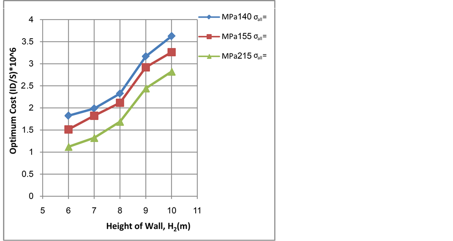
Considering the allowable stress of tie steel, the values of allowable stresses are given by BS449: Part 2: 1969 [12] . The values of 140, 215 in addition to 155 MPa, that is used in Section 4.1, are chosen in order to illustrate the effect of its variation on the optimum dimensions. The results obtained by varying the properties of materials are shown in Figures 11-13.
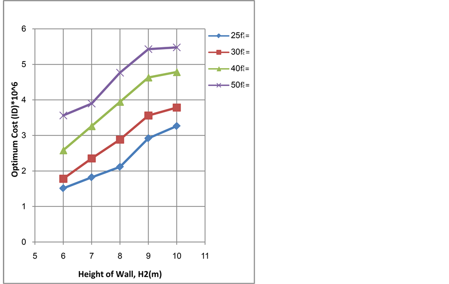
Figure 11. Optimum cost versus total height, H2, for different compressive strength values,
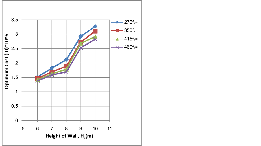
Figure 12. Optimum cost versus total height, H2, for different yield strength values, fy.
It can be realized that the compressive strength of concrete has an effect on the optimum thickness of stem and base. Increasing the concrete compressive strength leads to a reduction in the stem thickness and a reduction in the base thickness, consequently different steel areas are changed in each section.
Hence, it is clear from Figure 11 that the increasing of the concrete compressive strength leads to increase the minimum cost. Results reveal that the increase of steel strength leads to an effect on the dimensions and steel areas in the optimum sections, and the increase of the yield steel strength leads to a decrease in the minimum cost as notice from Figure 12. Therefore, the results indicate that it is economical to use steel of high strength in design.
It is clear from Figure 13 that the increase of the allowable stress of tie steel leads to decrease the minimum cost. Therefore, it is economical to use tie steel section with high allowable stress in design.
5. Proportions of Tied Back Retaining Wall
Dimensions of tied back retaining wall should be adequate for structural stability and to satisfy design requirements. So there is a need for tentative dimensions that may be used by the designer in the absence of other data though overly conservative.
Based on the used pressure coefficient values (4 to 6) kN/m3 and the wall total height (6 to 10) m, the developed program is utilized to find the values or ranges of some parameters relating to tied back retaining wall which give an optimum of such retaining structures. Tables 3-8 show some the results of this study.
6. Conclusions
The following conclusions may be drawn from the present study:
1) The minimum cost of tied back retaining wall increases as the total height H2 increases in a nonlinear relationship. This relation usually depends on many factors like material properties and the different unit prices.
2) The ranges of optimum dimensions as ratios from the wall height H2 for a tied back retaining wall are
Figure 13. Optimum cost versus total height, H2, for different allowable stress values, σall.
Table 3. The optimum values of tie spacing to wall height ratio, S/H2.
Table 4. The optimum values of stem thickness to wall height ratio, Ts/H2.
Table 5. The optimum values of base thickness to wall height ratio, Tb/H2.
Table 6. The optimum values of base width to wall height ratio, B/H2.
Table 7. The optimum values of upper tie position ratio, α.
Table 8. The optimum values of upper tie position ratio, β.
(0.135 to 0.257) for the distance between ties S, (0.038 to 0.051) for the thickness of the wall Ts, (0.055 to 0.083) for the thickness of the base Tb, and (0.609 to 0.794) for the width of the base B.
3) The outer tie position ratio, α, is from (0.56 to 0.781) times H1 and the outer tie position ratio, β, seems to be constant, about (0.92 to 1) times Bh.
4) It can be realized from Figures 4-13 that, there is a real irregularity in the trends of the relationships. This can attribute to the nature of the objective function, since the minimization of the cost is the main task of the program. The big number of design variables and selecting the optimum results from different methods are other minor reasons.
5) From cost point of view it is preferable to use low strength concrete and steel of high yield strength in the design of tied back retaining wall.
6) The increase of the allowable stress of tie steel leads to the decrease of the minimum cost. Therefore, it is economical to use tie steel section with high allowable stress in design.
Cite this paper
Nabeel A. Jasim,Ahmed M. Al-Yaqoobi, (2016) Optimum Design of Tied Back Retaining Wall. Open Journal of Civil Engineering,06,139-155. doi: 10.4236/ojce.2016.62013
References
- 1. Rao, S.S. (2009) Engineering Optimization: Theory and Practice. 4th Edition, John Wiley & Sons, Inc., Hoboken, New Jersey.
http://dx.doi.org/10.1002/9780470549124 - 2. Al-Janabi, A.I. (1983) The Structural Analysis of Tied Back Retaining Walls by Finite Element Method. M.Sc. Thesis, Universuty of Basrah, Basrah, Iraq.
- 3. Ceranic, B. and Fryer, C. (1999) A Constrained Simulated Annealing Approach to the Minimum Cost Design of Reinforced Concrete Cantilever Retaining Walls. Proceedings of 3rd World Congress on Structural and Multi-Disciplinary Optimization, New York, 593-595.
- 4. Ghazavi, M. and Heidarpour, A. (2003) Optimization of Counterfort Retaining Walls. Fourth International Conference of Earthquake Engineering and Seismology, Tehran, 2003.
- 5. Yepes, V., Alcala, J., Perea, C. and Vidosa, F. (2007) A Parametric Study of Optimum Earth-Retaining Walls by Simulated Annealing. Engineering Structures, 30, 821-830.
http://dx.doi.org/10.1016/j.engstruct.2007.05.023 - 6. Magbo, C.C., Sule, S. and Nwofor, T.C. (2012) Design Curves for Optimal Design of Anchored Sheet Pile Walls in Cohessionless Soils. Canadian Journal on Environmental, Construction and Civil Engineering, 3, 104-112.
- 7. Sable, K.S. and Patil, A. (2012) Comparision between Optimization and Conventional Catilever Retaining Wall by Using Optimtool in Matlab. International Journal of Engineering and Advanced Technology (IJEAT), 1, 255.
- 8. Goldberg, D.E. (1989) Genetic Algorithms in Search, Optimization, and Machine Learning. Addison-Wesley Publishing Company, USA.
- 9. Sivanandam, S.N. and Deepa, S.N. (2008) Introduction to Genetic Algorithms. Verlag, Berlin Heidelberg.
- 10. Bowles, J.E. (1986) Analytical and Computer Methods in Foundation Engineering. MsGraw-Hill, New York.
- 11. American Concrete Institute (2011) Building Code Requirements for Structural Concrete (ACI 318M-11) and Commentary, ACI Committee 318.
- 12. British Standards Institution (1969) The Use of Structural Steel in Building. BS 449, Part 2.


