Modern Mechanical Engineering
Vol.08 No.01(2018), Article ID:82741,16 pages
10.4236/mme.2018.81007
Thermal-Mechanical Coupled FE Analysis for Rotary Shaft Seals
György Szabó, Károly Váradi
Department of Machine and Product Design, Budapest University of Technology and Economics, Budapest, Hungary

Copyright © 2018 by authors and Scientific Research Publishing Inc.
This work is licensed under the Creative Commons Attribution International License (CC BY 4.0).
http://creativecommons.org/licenses/by/4.0/


Received: December 11, 2017; Accepted: February 25, 2018; Published: February 28, 2018
ABSTRACT
The aim of this paper is to model the steady-state condition of a rotary shaft seal (RSS) system. For this, an iterative thermal-mechanical algorithm was developed based on incremental finite element analyzes. The behavior of the seal’s rubber material was taken into account by a large-strain viscoelastic, so called generalized Maxwell model, based on Dynamic Mechanical Thermal Analyses (DMTA) and tensile measurements. The pre-loaded garter spring was modelled with a bilinear material model and the shaft was assumed to be linear elastic. The density, coefficient of thermal expansion and the thermal conductance of the materials were taken into consideration during simulation. The friction between the rotary shaft seal and the shaft was simplified and modelled as a constant parameter. The iterative algorithm was evaluated at two different times, right after assembly and 1 h after assembly, so that rubber material’s stress relaxation effects are also incorporated. The results show good correlation with the literature data, which state that the permissible temperature for NBR70 (nitrile butadiene rubber) material contacting with ~80 mm shaft diameter, rotating at 2600/min is 100˚C. The results show 107˚C and 104˚C for the two iterations. The effect of friction induced temperature, changes the width of the contact area between the seal and the shaft, and significantly reduces the contact pressure.
Keywords:
Coupled FE Analysis, Thermal-Mechanical Coupling, Rotary Shaft Seals, NBR Rubber, Viscoelasticity

1. Introduction
The most frequently used type of seals for the sealing of rotating shafts is the rotary shaft seals. Their complex design allows them to be used versatile in engines, drive trains, gearboxes, hydro-units, compressors, household- and industrial appliances [1] . The first rotary shaft seal was patented in 1938 by Walter Simmer [2] . The schematic representation of a modern rotary shaft seal can be seen in Figure 1.
The basic functions of these kinds of seals are to provide static tightness between the outer casing of the seal and the bore of the housing, and to provide static and dynamic tightness between the rotating shaft and the sealing lip, additionally, to prevent dust and dirt to ingress from the outside. The sealing mechanism of rotary shaft seals is composed of many individually important features [3] . First of all, the sealing lip is assembled onto the shaft with an overlap, which provides the static tightness between the shaft and the seal. The sealing lip design allows the seal to compensate eccentricity and run out of the shaft by a certain extent enhanced by a tension spring. The narrow neck region of the seal allows the lip to be flexible. The angle of the sealing lip on the oil side of the seal is larger than the one on air side. The reason for this is to generate steeper contact pressure rise on oil side, in order to prevent oil leakage of the system. The asymmetric contact pressure distribution and the circumferential force lead to a characteristic deformation of the seal lip contact surface [2] . These deformations, along with the rotating shaft, create a so called micro-pump effect, transferring the media back towards the oil side. The relative spring position is important because it affects the width of the contact area. All said above and the hardness of the seal’s rubber material have an influence on the total radial force, which must not be large, in order to keep friction low and to prevent excessive material wear, but must be large enough to provide sealing.
Many researchers have studied the behavior of rotary shaft seals. Their models can be distinguished between microscale and macroscale models. Microscale models usually simulate a small part of the seal system, which is physically accurate and close to reality, while macroscale models use higher scale physical models and base on simplified empirical approaches [4] .
Figure 1. Schematic representation and features of modern rotary shaft seals (a) with metal casing, (b) with rubber casing [3] .
Stakenborg first investigated the mechanical behavior of the sealing lip, and found, that the contact conditions governing the sealing mechanism are influenced by temperature [5] . With Ostayen, they studied the temperature-distribution in the contact zone of radial shaft seals [6] . They found, that much larger proportion of the heat generated in the contact zone dissipates through the shaft, and small amount of heat dissipates through the seal.
Kang and Sadeghi used microscale model utilizing elastohydrodynamic (EHD) theory to simulate the temperature distribution in the contact zone of the seal system [7] . They showed that the surface temperature of the sealing lip is higher than that of the shaft.
Lee and his co-workers studied the effect of thermal deformation, due to friction power generated in the contact zone [8] , and found that there is only a small influence on the contact pressure by thermal deformation. The authors used constant Mooney-Rivlin coefficients independent of the temperature distribution. In [9] and [10] the temperature distribution was taken into account. The authors used an iterative thermal mechanical model to calculate the contact pressure and friction between seal and shaft more accurately. [11] gives a detailed view in the contact temperature of rotary seals.
The dependence of the friction on temperature, lubricating conditions, load and relative speed is often neglected, however friction plays an inevitable role in the generated heat in RSS systems. A detailed empirical method on the dependence of friction on temperature can be found in [12] and it showed that the resulting overall friction is made up by dry and fluid friction. [13] and [14] also showed the dependence of coefficient of friction on lubricating conditions, and how much friction varies in dry, wet and mixed conditions.
In [15] a numerical EHD lubrication model was presented, with which simulations were performed. The results showed, that there is an optimal roughness amplitude of the shaft and deviating from it the coefficient of friction increases. Additionally, it shows that the increase of shaft roughness amplitude induces flow variations which can lead to leakage. In [16] it is shown, that the most influencing parameter on sealing mechanism is the seal lip roughness amplitude. Wenk and colleagues created a multi-scale model that incorporates measured surface roughness data of used radial shaft seals [17] . It is shown, that the surface roughness alters the ideal pressure distribution between the lip and shaft in a way that it alters significantly in both circumferential and axial directions. Furthermore, the study reveals the existence of striated angles in the surface of the lip, which may be generated by wear of the seal in tangentially sheared state. These two effects impact the reverse pumping tendency of the seal.
The aim of this paper is to create a numeric model, that is capable of modelling the steady-state condition of a rotary shaft seal. Ignoring the transient warming-up process, and taking into account the friction as a simplified, constant parameter. The implemented algorithm is based on coupled thermal-mechanical, incremental finite element (FE) analyzes.
2. Material Model
The large-strain viscoelastic material model used for the investigation of the rubber’s mechanical behavior in this FE analysis was previously developed and presented in a detailed manner in the authors’ previous articles [18] and [19] . To identify the parameters for the rubber’s material model, uniaxial tension, equal biaxial tension and pure shear test were performed, supplemented with Dynamic Mechanical Thermal Analysis (DMTA) data. The developed material model is based on a generalized Maxwell model. The response of the model can be seen in Figure 2. For the garter spring a bilinear material model was used to model the pre-loaded spring, which was developed by Z. Márton [20] . The thermal properties of the NBR rubber and the shaft were taken from P. Szűcs’ thesis [21] .
The summary of the mechanical properties of the shaft and the spring parts
Figure 2. Comparison of the response of the rubber’s large-strain viscoelastic material model (a) to the measured DMTA data, (b) to the measured data in uniaxial tension, pure shear and equal biaxial modes.
can be found in Table 1. For the thermal analysis, the material properties are summarized in Table 2, and the convection parameters between the different bodies are presented in Table 3 assuming axisymmetric models.
3. FE Model
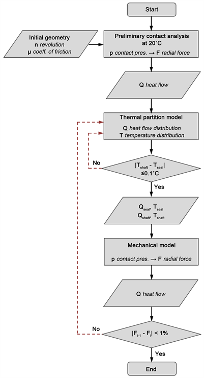
The aim of the analysis was to create a finite element model, that is capable of determining the steady-state thermal and mechanical behavior of a rotary shaft seal (RSS) and shaft assembly during normal operating conditions. To achieve this an iterative procedure was developed by the authors which involves an initial contact analysis, followed by iterative thermal and mechanical finite element analyzes. All of the FE analyzes were incremental.
As a first step an axisymmetric, initial contact analysis of the RSS system was performed. Input parameters were the initial geometry, the coefficient of friction, which was assumed to be 0.4 [9] , and the rotational speed of the shaft. For the NBR rubber material, the allowed rotational speed is ~2600/min when it is used with a shaft of an outside diameter of 80 mm [2] [3] . As a result of this initial contact analysis, the contact pressure distribution is determined. Integrating the normal contact pressure on the contact length, and multiplying it by the circumference of the shaft, the complete radial force of the seal can be calculated.
(1)
Table 1. Material properties of the shaft and spring parts.
Table 2. Summary of the thermal properties of the materials.
Table 3. Summary of other thermal properties.
(2)
Multiplying the total radial force by the circumferential speed of the shaft and the coefficient of friction one can get the total heat flow generated by friction.
(3)
(4)
This total heat flow was divided by an iterative thermal partition analysis in order to determine what percentage of the total heat flow contributes to heat the RSS system and the shaft. The boundary condition of the analysis was, that the temperature of the seal and the shaft is identical in the contact zone. The results of this analysis showed, that less than 1% of heat dissipates through the seal, and more than 99% of it heats the shaft directly.
The obtained temperature data was then mapped onto the parts of the mechanical model as a temperature load. As the material model of the rubber is temperature dependent, and the thermal expansion of the parts were taken into consideration, the result of the mechanical model is the contact pressure distribution between the seal and the shaft modified by the aforementioned factors. This contact pressure distribution was again used to calculate the total heat flow, and this modified heat flow was divided by the thermal partition analysis, where the procedure started over. The iteration of the results ended when the change of the total radial force became less than 0.5%. The flow chart of the procedure can be seen in Figure 3.
This method allows to calculate the steady-state thermal condition of the RSS system, and to take into account the temperature dependent mechanical behavior of the rubber material, thus to get a complex view of the operation of the RSS system. Disadvantage of the method is that it does not incorporate the change in the friction coefficient due to the change in temperature, speed and load.
Figure 4 shows the mesh of both the thermal and the mechanical models for initial position of the seal, before assembly. Quadratic and triangular axisymmetric elements were used. The average element size is 0.5 mm for the shaft, 0.2 mm for the metal insert and 0.1 mm for the spring. The contacting edge of the shaft was refined with 0.02 mm size elements. The radial shaft seal had 0.1 mm average element size, locally refined with 0.04 mm elements on the contacting edges. In the proximity of the sealing lip 0.01 mm elements were used. Very close to the lip 0.001 mm elements were used to enhance accuracy. The neck of the RSS system was refined with 0.04 mm size elements. Frictional contact was used between the seal and the shaft with a coefficient of friction of 0.4 [20] . The contact between the seal and the metal insert was bonded, and between the seal and the spring it was frictional with 0.1 coefficient friction. The radius of the sealing lip’s fillet is 0.025 mm. The simulations were carried out in ANSYS Workbench 18.2 software [22] .
3.1. Thermal Model
The thermal model is used in the iteration process to divide the total heat flow
Figure 3. Flow chart of the developed iterative procedure for steady-state thermal and mechanical analysis of rotary shaft seals.
between the rotary shaft seal and the shaft. The total heat flow is divided if the temperatures in the contact zone are equal. It is found that less than 1% of the heat goes into the seal, and the vast majority, more than 99% of the heat transfers to the shaft. This is because of the better thermal conductivity of the steel material, as it can transfer more heat.
The thermal boundary conditions can be seen in Figure 5 and in Figure 6. On the upper edge of the seal thermal convection was applied, to take into account the effect of the housing. Onto the right side of the seal thermal convection was applied to simulate the effect of the ambient temperature. Onto the outer edges of the seal’s left side, in order to simulate the cooling oil’s effect thermal convection was applied. The heat flow is applied on the contacting area of the seal lip. For the shaft, the contacting surface was divided into three sections. From the left, the convection to oil, from the right the convection to air was simulated. In between the heat flow was taken into account. The ambient temperature was set to 20˚C, while the oil temperature was 80˚C. The applied material parameters for the thermal model can be seen in Table 2, and the convection parameters are in Table 3.
3.2. Mechanical Model
The mechanical model was used to map the temperature load onto the parts, and take into account the effects of temperature, such as thermal expansion and temperature dependent material behavior.
Figure 4. Mesh of thermal and mechanical models.
Figure 5. Thermal boundary conditions of the rotary shaft seal.
Figure 6. Thermal boundary conditions of the shaft.
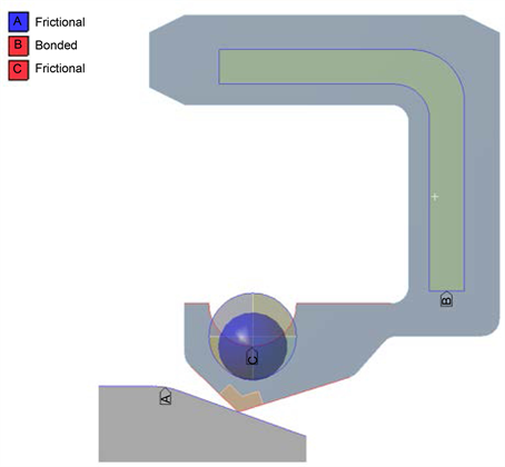
The boundary conditions of the mechanical model can be seen in Figure 7 and Figure 8. During the simulation, first the spring was installed and seated on its place in the seal, to add necessary pre-load to the seal after installation. Second, the seal was assembled to the shaft. This was done by moving the shaft 5 mm to the right, while the RSS was held fixed on its upper edge. As the simulation is axisymmetric, that shaft was only allowed to move in horizontal direction. To enhance convergence a chamfer was added to the shaft, to help the installation process. Three contacts were defined in the model as seen in Figure 9. One bonded contact between the seal and the metal insert of the seal. One frictional contact between seal and the spring with μ = 0.1, and one frictional contact between the seal’s sealing lip and the outside edge of the shaft.
Two kinds of iterations were carried out. For the first one, the contact pressure was evaluated right after assembly, after temperature load was applied. For the second one, the contact pressure was evaluated 1 h after assembly and temperature load had been applied. By this, the time-dependent rubber material’s stress-relaxation properties could be addressed, so that the steady-state condition of the seal could be further approximated. The results of the two iterations were then compared.
4. Results
4.1. Results at t = 0 s (after Assembly)
Figure 10 shows the contact pressure distribution for the first iteration. The preliminary contact analysis’ and the converged iteration’s pressure distributions are compared. It is seen that for the initial contact analysis the contact length is ~0.1 mm and the maximal contact pressure is ~3.4 MPa. This result represents the rubber seal’s behavior at room temperature, so no temperature load was assumed. Compared to this, for the converged iteration the contact length comes to ~0.12 mm and the maximal contact pressure is ~2.5 MPa. This is purely because of the temperature dependent behavior of the rubber material. As the material softens at high temperatures the contact pressure decreases. This behavior can also be followed on the material’s DMTA (Dynamic Mechanical Thermal Analysis) curve. The softer rubber material means, that due to the more or less equal amount of preload generated by the spring, more material comes in
Figure 7. Boundary conditions of the rotary shaft seal.
Figure 8. Boundary conditions of the shaft.
contact with the shaft in the contact zone, hence the width of the zone enlarges.
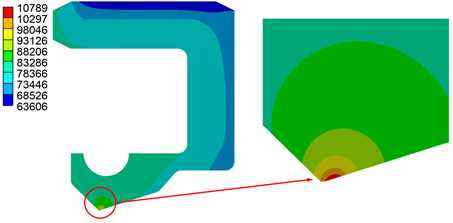
Figure 11 and Figure 12 show the temperature distribution of the thermal model of the rotary shaft seal and the shaft for the converged iteration. It is seen, that the maximal values are identical. The maximal temperature is present in a small environment of the contact zone. On the sealing lip area of the RSS system the temperature is ~80˚C, the minimal temperature occurs to be ~60˚C, on the casing of the sealing, where it contacts with the housing. The results for the second type of iteration, where the contact pressure was evaluated 1 h after assembly are very similar to the ones presented below, so only the temperature results of the first iteration is shown.
Figure 9. Applied contacts for the mechanical model.
Figure 10. Contact pressure distribution for the preliminary contact analysis and for the converged iteration for the first iteration (evaluated after assembly).
The calculated parameters of the first iteration are summarized in Table 4. One can see, that the steady-state temperature for the converged iteration is ~108˚C. This correlates well with the literature data that state, that the allowed temperature maximal temperature for NBR rubber material is 100˚C [1] and [3] . Further increasing the rotational speed of the shaft or applying too much pre-load on the sealing lip would generate more heat that eventually deteriorates
Figure 11. Temperature distribution of the rotary shaft seal for the converged iteration.
Figure 12. Temperature distribution of the shaft for the converged iteration.
Table 4. Results of the iteration, evaluated 1s after temperature load is applied.
the material and causes the seal to fail.
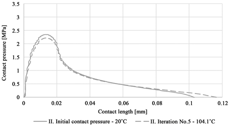
4.2. Results at t = 3600 s (1 h after Assembly)
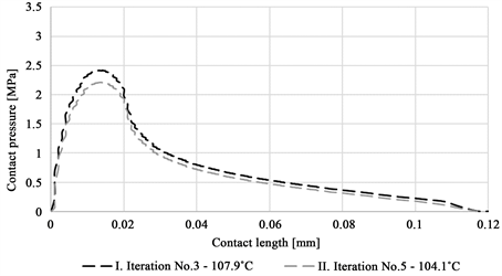
Figure 13 shows the contact pressure distribution of the second iteration, where the total radial force was evaluated 1 h after assembly. The results show that the initial contact pressure analysis’ pressure distribution curve and the converged analysis’ curve, are very much alike. The enlargement of the contact zone and the decrease of maximum contact pressure can also be observed for this case. The less significant drop in maximum contact pressure comes from the fact, that the rubber material is viscoelastic and the time-temperature equivalence principle applies. This means, that the material’s behavior for long time periods are similar to that of high temperatures [23] .
Table 5 summarizes the iteration parameters. In Figure 14 the pressure
Figure 13.Contact pressure distribution for the preliminary contact analysis and for the converged iteration for the second iteration (evaluated 1 h after assembly).
Figure 14. Comparison of the contact pressure distribution for the two types of converged iteration.
Table 5. Results of the iteration, evaluated 1 h after temperature load is applied.
distribution of the two iterations are compared. It is seen that the shape of the two curves are almost identical, the curve for the second iteration gives lower values. This can be attributed to the stress relaxation behavior of the rubber material was taken into account as the contact pressure was evaluated 1 h after assembly. Compared to the effect of temperature, the effect of stress-relaxation plays a smaller role in the steady-state condition of the contact pressure distribution, thus the arising total radial force, nonetheless further improves the accuracy of the iterative method as the steady state temperature comes to ~104˚C.
5. Conclusions
For the analysis of rotary shaft seals, an iterative algorithm based on incremental finite element analyzes was implemented. The FE analysis is a one way coupled thermal-mechanical analysis, where the initial parameters are determined by a preliminary contact analysis. The FE models incorporate the modeling of the steel spring which was modelled by a bilinear isotropic hardening material model and responsible for the adequate pre-load of the sealing lip.
Summarizing the results one can conclude, that the effect of temperature cannot be neglected when analyzing rotary shaft seals during operation. The friction generated heat alters the mechanical strength of the material―softens it―and has a great impact on the overall behavior of the seal.
With modifying the iteration process so that it takes into account the long term behavior of the rubber, the results can be further improved. Nevertheless, the number of iterations and thus the computational time increases and the accuracy of the results only improves to a minor extent, which means that the application of the second iteration algorithm may not be beneficial overall.
The authors’ intention is to further refine the model, by measuring the friction between the rotating shaft and the sealing lip, depending on temperature, load, relative speed and lubricating conditions, to be able to model the generated heat in the contact zone, and to incorporate wear to the model.
Acknowledgements
Hereby we would like to express our gratitude to Prof. Dr. Balázs Magyar at the Technical University of Kaiserslautern for letting us utilize the measured data and results of their researches’.
Cite this paper
Szabó, Gy. and Váradi, K. (2018) Thermal-Mechanical Coupled FE Analysis for Rotary Shaft Seals. Modern Mechanical Engineering, 8, 95-110. https://doi.org/10.4236/mme.2018.81007
References
- 1. Freudenberg Sealing Technologies (2015) Technical Manual: Simmerrings and Rotary Seals. https://www.fst.com/-/media/files/fst,-d-,com/technical-manuals/en/fst_technical_manual_2015_en.ashx
- 2. SKF (2013) Industrial Shaft Seals. http://www.skf.com/binary/83-129139/Industrial-shaft-seals---10919_2-EN.pdf
- 3. Simmer, W. (1938) Aus elastischem Werkstoff bestehende Dichtung für umlaufende Wellen oder hin und her gehende Stangen. Patentschrift DE729128C.
- 4. Frolich, D., Magyar, B. and Sauer, B. (2014) A Comprehensive Model of Wear, Friction and Contact Temperature in Radial Shaft Seals. Wear, 311, 71-80. https://doi.org/10.1016/j.wear.2013.12.030
- 5. Stakenborg, M.J.L. (1988) On the Sealing Mechanism of Radial Lip Seals. Tribology International, 21, 335-340. https://doi.org/10.1016/0301-679X(88)90110-7
- 6. Stakenborg, M.J.L. and Ostayen, R.A.J. (1989) Radial Lip Seals, Thermal Aspects. Tribological Design of Machine Elements, 14, 79-88. https://doi.org/10.1016/S0167-8922(08)70183-4
- 7. Kang, Y.S. and Sadeghi, F. (1997) Numerical Analysis of Temperature Distribution at the Lip Seal-Shaft Interface. Journal of Tribology, 119, 273-278. http://doi.org/10.1115/1.2833188
- 8. Lee, C., Lin, C., Jian, R. and Wen, C. (2006) Simulation and Experimentation on the Contact Width and Pressure Distribution of Lip Seals. Tribology International, 39, 915-920. http://doi.org/10.1016/j.triboint.2005.09.002
- 9. Meyer, S., von Estorff, O., Feldmann, M. and Wollesen, V.M. (2006) Test on Rotary Sfaft Lip Type Seals and Finiite Element Simulation for Validation of Material Laws for Elastomers. 14th International Sealing Conference, Stuttgart, 10-11 October 2006, 522-533.
- 10. Plath, S., Meyer, S. and Wollesen, V.M. (2005) Friction Torque of a Rotary Shaft Seal Lip Type Seal—A Comparison between Test Results and Finite Element Simulation. Mechanika, 4, 55-59.
- 11. Daubner, A. and Haas, W. (2009) Simulation der Temperatur im und am Reibkontakt, Computational Fluid Dynamics. NAFEMS Magazine, 62-71.
- 12. Engelke, T. (2011) Friction Torque of a Rotary Shaft Lip Type Seal—A Comparison Between Test Results and Finite Element Simulation. Ph.D. Thesis, Gottfried Wilhelm Leibniz University Hannover, Hannover.
- 13. Deleau, F., Mazuyer, D. and Koenen A. (2009) Sliding Friction at Elastomer/Glass Contact: Influence of the Wetting Conditions and Instability Analysis. Tribology International, 42, 149-159. https://doi.org/10.1016/j.triboint.2008.04.012
- 14. Bódai, G. and Goda, T.J. (2014) Sliding Friction of Wiper Blade: Measurement, FE Modeling and Mixed Friction Simulation. Tribology International, 70, 63-74. https://doi.org/10.1016/j.triboint.2013.07.013
- 15. El Gadari, M., Fatu, A and Hajjam, M. (2015) Shaft Roughness Effect on Elasto-Hydrodynamic Lubrication of Rotary Lip Seals: Experimentation and Numerical Simulation. Tribology International, 88, 218-227. https://doi.org/10.1016/j.triboint.2015.03.013
- 16. El Gadari, M., Fatu, A. and Hajjam, M. (2016) Effect of Grooved Shaft on the Rotary Lip Seal Performance in Transient Condition: Elasto-Hydrodynamic Simulations. Tribology International, 93, 411-418. https://doi.org/10.1016/j.triboint.2015.09.031
- 17. Wenk, J.F., Stephens, L.S., Lattime, S.B and Weatherly, D. (2016) A Multi-Scale Finite Element Contact Model Using Measured Surface Roughness for a Radial Lip Seal. Tribology International, 97, 288-301. https://doi.org/10.1016/j.triboint.2016.01.035
- 18. Szabó, Gy. and Váradi, K. (2017) Large Strain Viscoelastic Material Models for Deformation, Stress and Strain Analysis of O-Rings. Periodica Polytechnica (submitted).
- 19. Szabó, Gy. and Vádadi, K. (2017) Failure Mechanism of O-Ring Seals under Extreme Operating Conditions. Modern Mechanical Engineering, XXX, 121-120.
- 20. Márton, Z. (2011) Contact Behaviour of an Elastomeric Radial Shaft Seal (Budapest). MSc. Thesis, Budapest University of Technology and Economics, Budapest.
- 21. Szucs, P. (2014) Modellierung der Warmeentwicklung am mehrachsigen Dichtprüfapparat (Budapest). MSc. Thesis, Budapest University of Technology and Economics, Budapest.
- 22. ANSYS Inc. (2017) ANSYS Help 18.2. ANSYS Inc., Canonsburg.
- 23. Urzhumcev, Y.S. and Maximov, R.D. (1982) Prognostika deformativnosti polimernyh materialnov (Deformation Prognosis of Polymer Materials). Riga.


