Modern Mechanical Engineering
Vol.2 No.3(2012), Article ID:22205,6 pages DOI:10.4236/mme.2012.23014
Design Optimization of Cam & Follower Mechanism of an Internal Combustion Engine for Improving the Engine Efficiency
1Research and Development, MAN Trucks India Pvt. Ltd., Pune, India
2Department of Mechanical Engineering, Rajarambapu Institute of Technology, Islampur, India
3Department of Mechanical Engineering, M. E. Society’s College of Engineering, Pune, India
4KIT College of Engineering, Kolhapur, India
Email: malimaheshr@yahoo.com, shgawande@gmail.com
Received March 29, 2012; revised May 5, 2012; accepted May 14, 2012
Keywords: Follower & Cam; Point Contact; Vibration Analysis; Finite Element Approach [FEA]
ABSTRACT
The current cam and follower mechanism in four stroke internal combustion engine employs a flat follower. In this work an attempt is made to change the flat face of follower to a curved face follower, so that the required point contact can be achieved. As line contact between existing cam and follower mechanism results in high frictional losses which results in low mechanical efficiency. It is observed that the frequency of vibration in the existing and modified cam and follower mechanism remains almost same. The finite element approach is used to perform the analysis.
1. Introduction
Cam and follower mechanism is preferred over a wide variety of internal combustion engines because due to the cam and follower it is possible to obtain an unlimited variety of motions. Again the cam and follower has a very important function in the operation of many classes of machines, especially those of the automatic type, such as printing presses, shoe machinery, textile machinery, gear-cutting machines, screw machines etc. The cam may be defined as a machine element having a curved outline or a curved groove, which, by its oscillation or rotation motion, gives a predetermined specified motion to another element called the follower. In other word, cam mechanism transforms a rotational or oscillating motion to a translating or linear motion. In fact, cam can be used to obtain unusual or irregular motion that would be difficult to obtain from other linkage. The variety of different types of cam and follower systems that one can choose from is quite broad which depends on the shape of contacting surface of the cam and the profile of the follower. The existing cams used in internal combustion engines are made in a variety of forms which have a line contact with follower. As line contact between current cam and follower mechanism results in high frictional losses which results in low mechanical efficiency. Hence in this work an attempt is made to change the flat face of follower to a curved face follower, so that the required point contact can be achieved to minimize frictional losses.
Valves in distribution systems of internal combustion engines must ensure a suitable filling of cylinders in gasoline-air mixture for SI engines and in air for Compression ignition engines. On the other hand, for high engine speeds, valves may not have time to return to initial positions. It follows a power loss and in certain cases interference between the valve head and piston causing a broken engine [1,2]. The dynamic behavior of the system camshaft, follower, push-rod and valve is in a great importance in the good working of the system [3]. From design phases, engineers can predict this dynamic behavior as function of the different parameters of the engine valve train components. Many researchers who were interested in this research field work on different aspect like variable valve timing. Through computer modeling, experimental validation, and robust optimal design strategies David [4] showed that it is possible to develop optimal design to produce optimal valve train systems. Choi [5] was interested in the elaboration of camshaft lobes profiles using implicit filtering algorithm helping parameter identification and optimization in automotive valve train design. Cardona [6] presented a methodology to design cams for motor engine valve trains using a constrained optimization algorithm in order to maximize the time integral of the valve area opened to gas flow. He observed that profile errors can have a large influence on the dynamic performance of such high-speed follower cam systems. Kim [7] used a lumped mass-springdamper to predict the dynamic behavior of cam-valve system which gives concordant results compared with experimental tests for the evaluation of contact forces in the system. Jeon [8] stated that with experimental and simulation results that optimizing a cam profile can increase the valve lift area while reducing the cam acceleration and the peak pushrod force. It can also avoid the jump phenomenon of the follower observed at certain. Teodorescu [9] presented an analysis of a line of valve trains in a four-cylinder, four-stroke in-line diesel engine in order to predict the vibration signature taking into account frictional and contact forces.
According to Khin [10] a cam mechanism usually consists of two moving elements, the cam and the follower, mounted on a fixed frame. A cam may be defined as a machine element having a curved outline or a curved groove, which, by its oscillation or rotation motion, gives a predetermined specified motion to another element called the follower. By proper location of the follower pivot, it becomes virtually impossible to jump the follower, no matter how steep the cam surface. The extreme limiting condition is to make the pressure angle small enough to prevent the cam normal force from passing through the follower pivot. Therefore, the side thrust will not exit with the property designed oscillating roller follower. Whereas as Desai [11] the computer aided kinematic and dynamic analysis of cam and follower mechanism becomes very important for desired and required performance of the internal combustion engines. The kinematic analysis of mechanism helps in answering many questions related to motion of the follower and dynamic analysis is used to visualize the actual behavior of follower. Also according to Yuan [12] it is observed that the cam is opening and closing the valve at 1200 rpm. Hence the complete valve cycle is completed in 1/3 camshaft revolution, or 0.01 sec. Rejab [13] work on evaluation of profiles for disk cams with in-line roller followers to obtained points on a cam with roller followers. From analysis it is observed the coordinates of the centre of the follower are required at small increments of the cam angle in which analysis can be easily programmed and depend only on the follower coordinates and not the follower type.
Hence in order to consider the effect of profile of the follower, in this work an attempt is made to convert the existing line contact [as shown in Figure 1] into modified point contact to improve engine mechanical efficiency by reducing frictional losses.
2. Problem Definition and Objective
Most of the internal combustion engines used in various applications such as automotive to power generation have roller cam and follower mechanisms, having a line contact between the cam and follower as shown in Figure 1. In order to improve the mechanical efficiency of the mechanism it is observed that to change the line contact to a point contact. Hence in this work an attempt is made to convert the flat face of follower to a curved face profile with inclination of curved face angle 24˚.
3. Modal Analysis
Modal analysis of roller follower is performed by Ansys software to determine the vibrations characteristics such as natural frequencies and mode shapes.
4. Solid Modeling of Follower
To perform finite element analysis of roller follower, the solid model of the same is essential. Figure 2 shows a solid model of roller follower.
5. Finite Element Analysis Procedure
Roller follower first modeled in PRO/E WILDFIRE which is excellent CAD software, which makes modeling so easy and user friendly. The model is then transferred in IGES format and exported into the Analysis software ANSYS 11.0. The Follower is analyzed in ANSYS in
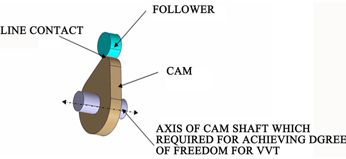
Figure 1. Existing cam and follower mechanism.
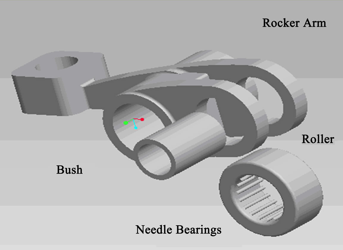
Figure 2. Solid model of roller follower.
three steps. First is preprocessing which involves modeling, geometric clean up, element property definition and meshing. Next step includes solution of problem, which involves imposing boundary conditions on the model and then solution runs. Next in sequence is post processing, which involves analyzing the results plotting different parameters like stress, strain, natural frequency. The Figure 3 shows step by step procedure involved in the analysis.
5.1. Finite Element Mesh Generation and Contact Element Type
The objective in building a solid model is to mesh that model with nodes and elements. Once the creation of solid model is completed, set element attributes and establishing meshing controls, which turn the ANSYS program to generate the finite element mesh. For defining the elements attributes, the user has to select the correct element type. This is most important task in finite element analysis because it decides the accuracy and computational time of analysis.
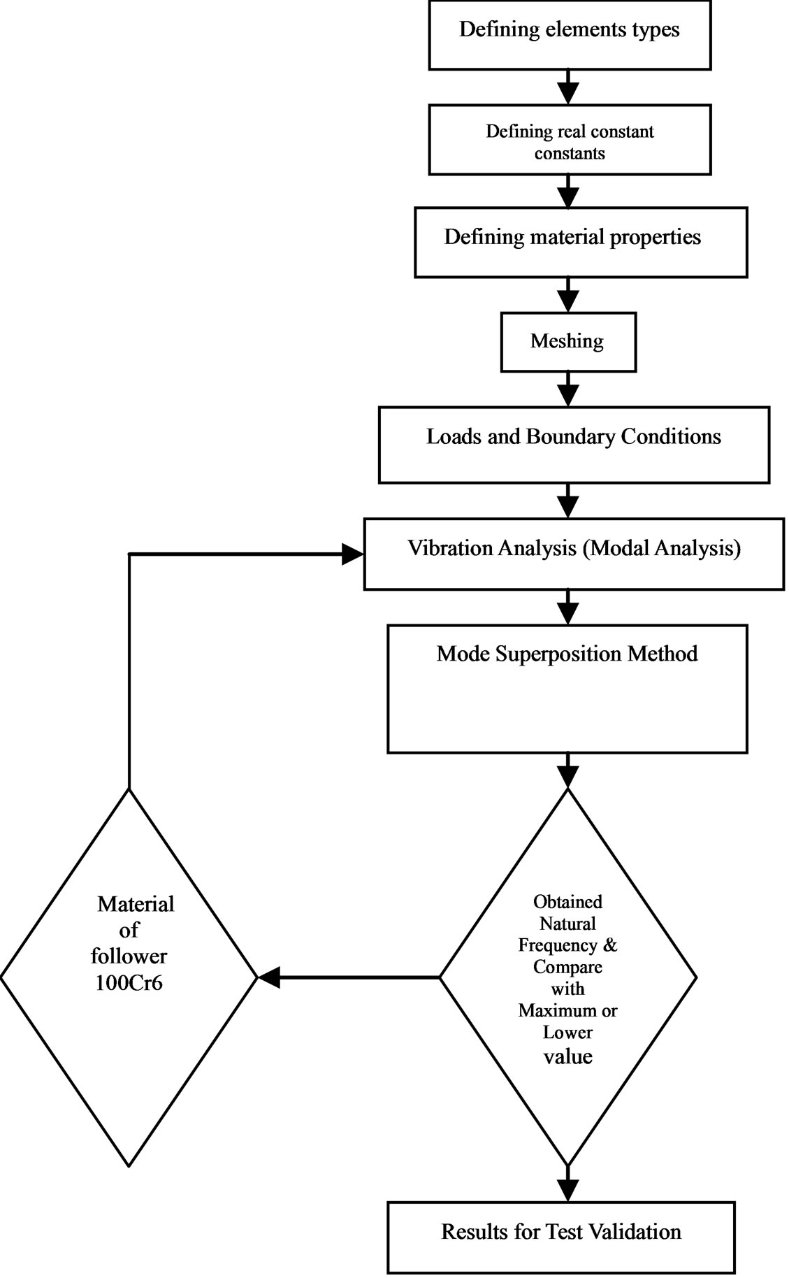
Figure 3. Finite element analysis procedure.
In this work Solid 90 element was used as element type. Solid 90 is a higher order version of the 3-D eight node thermal element (Solid 70). The element has 20 nodes with a single degree of freedom, temperature, at each node. The 20 node elements have compatible temperature shapes and are well suited to model curved boundaries. The 20 node thermal element is applicable to a 3-D, steady-state or transient thermal analysis. In this work Solid 90 is used for meshing of body of follower. The type of meshing used for follower is FREE mesh which is controlled by two parameters assigned to each mesh surface or volume that affect the size the elements generated. The meshed model and contact region is shown in Figure 4.
5.2. Boundary Conditions
A free modal analysis was performed to determine the natural frequencies of the existing follower and modified follower by Ansys software. Block Lancoz solver was used and expansion pass settings were set as 12 modes to extract and 12 modes to expand. Zero to infinity range was set to calculate the natural frequencies for existing and modified follower as shown in Figures 5 and 9.
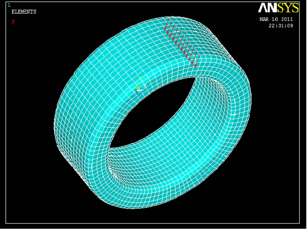
Figure 4. Meshed model of follower.
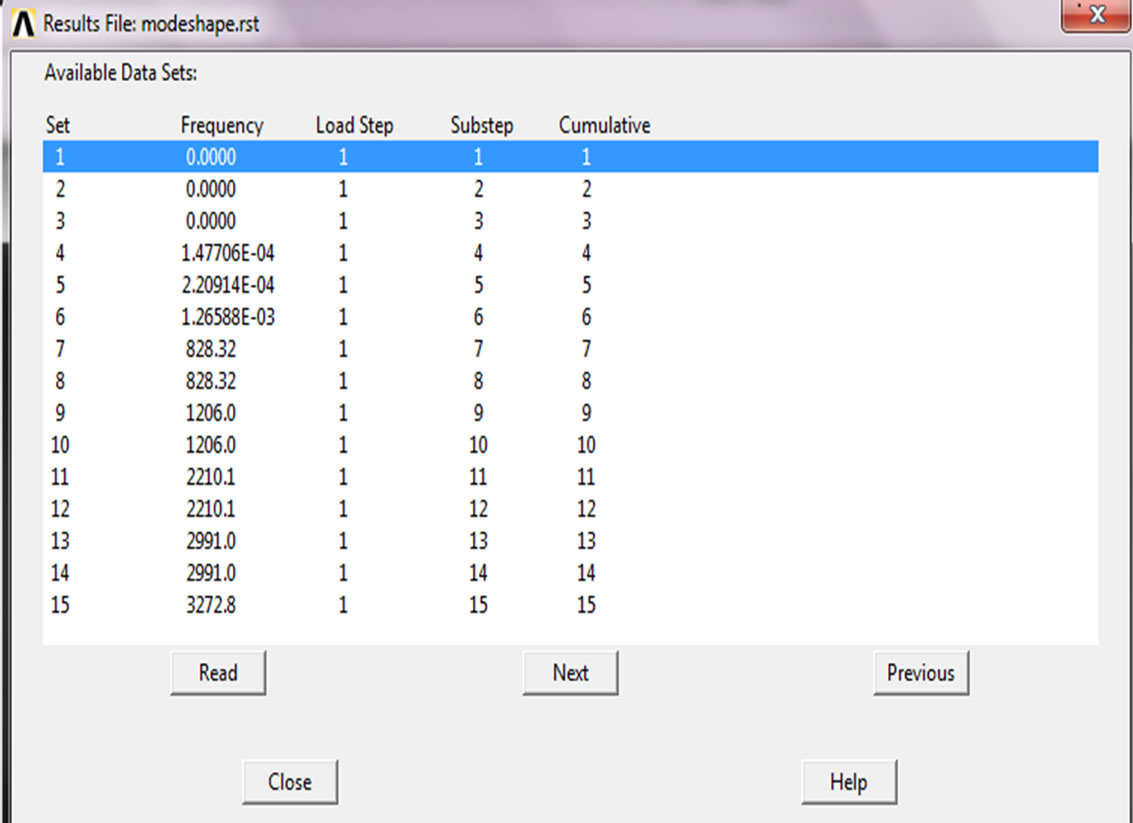
Figure 5. First 15 modes of vibration.
5.3. Analysis
In this section detail of finite element analysis and element behavior is given.
5.3.1. Natural Frequency of Existing Follower with Line Contact
The Figure 5 shows the frequency range for 15 sets of the existing follower with line contact which is fixed and this same frequency range used in the modified roller follower.
Figure 6 shows the modal analysis at the 828.32 Hz frequency and element behavior. Red colour zone indicates the deformation of existing roller follower having range from 16.015 mm [min.] to 17.436 mm [max.]. Blue colour zone indicates the deformation of existing roller follower having range from 4.642 mm [min.] to 6.064 mm [max.]. Figure 7 shows the modal analysis at the 1206 Hz frequency & element behavior. Red colour zone indicates the deformation of existing roller follower having range from 22.439 mm [min.] to 25.173 mm [max.]. Blue colour zone indicates the deformation of existing roller follower having range from 0.569 mm [min.] to 3.304 mm [max.]. Figure 8 shows the modal analysis at the 3272.8 Hz frequency & element behavior. Red colour zone indicates the deformation of existing roller follower having range from 21.649 mm [min.] to 23.41 mm [max.]. Blue colour zone indicates the deformation of existing roller follower having range from 7.558 mm [min.] to 9.319 mm [max.]. All these frequency range were used in existing follower and same frequency range and steps were followed in modified follower.
5.3.2. Natural Frequency of a Modified Roller Follower
Figure 9 shows the frequency range for 15 sets which were used in the existing follower with line contact are used in the modified roller follower.
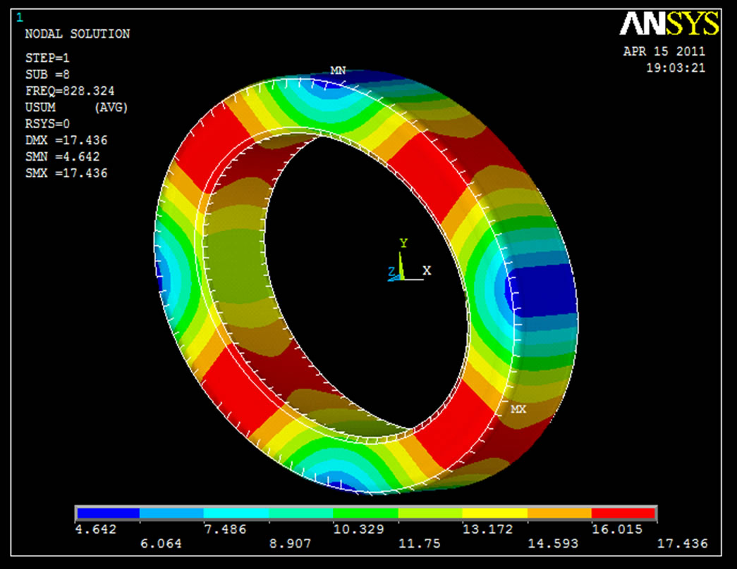
Figure 6. Nodal displacement solution 7th frequency (828.32 Hz).
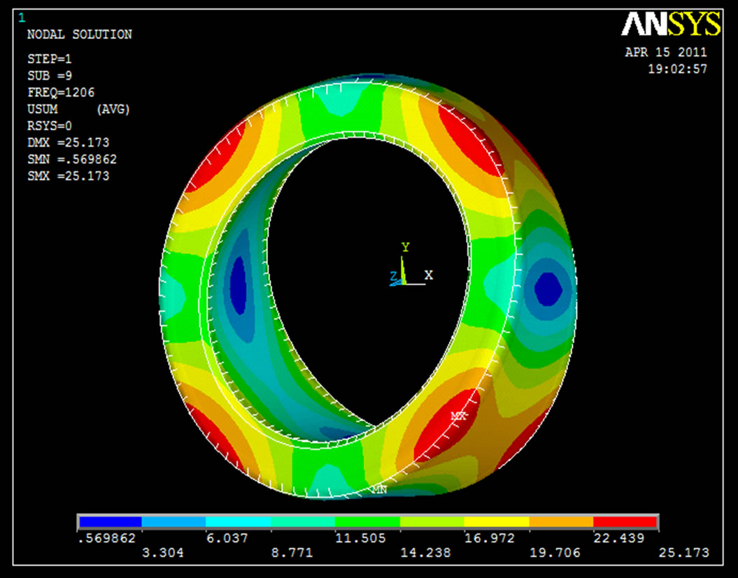
Figure 7. Nodal displacement solution 10th frequency (1206 Hz).
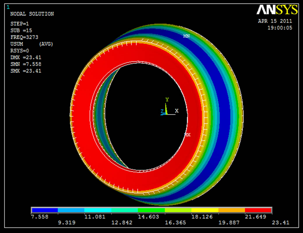
Figure 8. Nodal Displacement Solution 15th Frequency (3272.8Hz).
Figure 9. First 15 modes of vibration.
Figure 10 shows the Modal Analysis and element behavior of modified follower under frequency of 953.60 Hz. Red colour zone indicates the deformation of modified roller follower having range from 13.898 mm [min.] to 15.256 mm [max.]. Blue colour zone indicates the deformation of modified roller follower having range from 3.034 mm [min.] to 4.392 mm [max.]. Figure 11 shows the Modal Analysis and element behavior of modified follower under frequency of 1284.2 Hz. Red colour zone indicates the deformation of modified roller follower having range from 18.201 mm [min.] to 20.416 mm [max.]. Blue colour zone indicates the deformation of modified roller follower having range from 0.477 mm [min.] to 2.692 mm [max.]. Figure 12 shows the modal
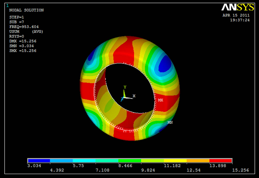
Figure 10. Nodal displacement solution 7th frequency (953.60 Hz).
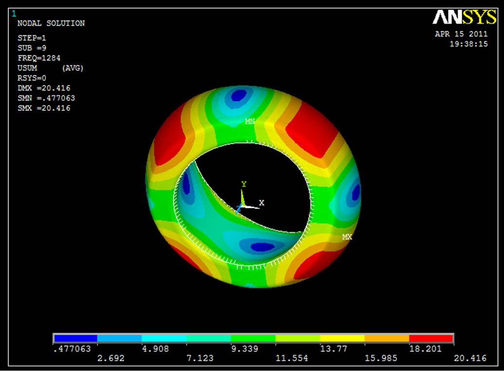
Figure 11. Nodal displacement solution 10th frequency (1284.2 Hz).
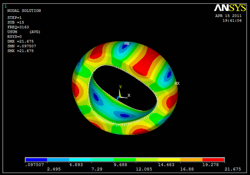
Figure 12. Nodal displacement solution 15th frequency (3162.7 Hz).
analysis and element behavior of modified follower under frequency of 3162.7 Hz. Red colour zone indicates the deformation of modified roller follower having range from 19.278 mm [min.] to 21.675 mm [max.]. Blue colour zone indicates the deformation of modified roller follower having range from 0.0975 mm [min.] to 2.495 mm [max.].
6. Results and Discussion
Modal analysis of existing and modified follower is carried out. As per the conditions initially frequency range was fixed and then the Modal analysis is performed. Frequency range of modified roller follower shows a very good match with the frequency range of existing roller follower. The obtained frequency range of existing roller follower is 828.32 Hz (Figure 6) to 3272.8 Hz (Figure 8) and for modified roller is 953.60 Hz (Figure 10) to 3162.7 Hz (Figure 12). As frequency range of modified roller follower is within the frequency range of existing roller follower. Thus, the modified design proves to be safe. From modal analysis it is observed that the maximum values of deformation for modified roller follower is 21.675 mm, while for existing roller follower is 23.41 mm for the obtained frequency. This shows modified roller follower deforms comparatively less as compared existing roller follower. This indicates change of the flat face of roller follower to a curved face roller follower mechanism results in low frictional losses due to point contact which results in improved in mechanical efficiency of internal combustion engine by 65% to 70%.
7. Conclusion
In this work finite element approach is used to optimize the shape of flat face of existing follower into a curved face of modified follower, so that the required point contact can be achieved. Frequency range of modified roller follower shows a very good match with the frequency range of existing roller follower. The obtained frequency range of existing roller follower is 828.32 Hz (Figure 6) to 3272.8 Hz (Figure 8) and for modified roller is 953.60 Hz (Figure 10) to 3162.7 Hz (Figure 12). As frequency range of modified roller follower is within the frequency range of existing roller follower, the modified design proves to be safe. From modal analysis it is observed that the maximum values of deformation for modified roller follower is 21.675 mm, while for existing roller follower is 23.41 mm. This shows modified roller follower deforms comparatively less as compared existing roller follower. This indicates change of the flat face of roller follower to a curved face roller follower mechanism results in low frictional losses due point contact which results in improved in mechanical efficiency of internal combustion engine by 65% to 70%.
REFERENCES
- H. Heisler, “Advanced Engine Technology,” 2nd Edition, Butterworth-Heinmann, Oxford, 2002.
- M. Husselman, “Modelling and Verification of Valve Train Dynamics in Engines,” M.Sc. Thesis, Stellenbosch University, Stellenbosch, 2005.
- R. L. Norton and R. G. Mosier, “Cam Design and Manufacturing Handbook,” Industrial Press, Inc., New York, 2002.
- J. W. David, C. Y. Cheng, T. D. Choi, C. T. Kelley and J. Gablonsky, “Optimal Design of High Speed Mechanical Systems,” North Carolina State University, Raleigh, Tech. Rep. CRSC-TR97-18, 1997.
- T. D. Choi, C. T. Eslinger, O. J. Kelley, J. W. David and M. Etheridge, “Optimization of Automotive Valve Train Components with Implicit Filtering,” Optimization and Engineering, Vol. 1, No. 1, 2000, pp. 9-27. doi:10.1023/A:1010071821464
- A. Cardona, E. Lens and N. Nigro, “Optimal Design of Cams,” Multibody System Dynamics, Vol. 7, No. 3, 2002, pp. 285-305. doi:10.1023/A:1015278213069
- W. J. Kim, H. S. Jeon and Y. S. Park, “Contact Force Prediction and Experimental Verification on an OHC Finger-Follower Type Cam Valve System,” Experimental Mechanics, Vol. 31, No. 2, 1991, pp. 150-156. doi:10.1007/BF02327568
- H. S. Jeon, K. J. Park and Y.-S. Park, “An Optimal Cam Profile Design Considering Dynamic Characteristics of a Cam Valve System,” Experimental Mechanics, Vol. 29, No. 4, 1989, pp. 357-363. doi:10.1007/BF02323851
- M. Teodorescu, M. Kushwaha, H. Rahnejat and D. Taraza, “Elastodynamic Transient Analysis of a Four-Cylinder Valve Train System with Camshaft Flexibility,” Proceedings of the Institution of Mechanical Engineers, Part K: Journal of Multi-Body Dynamics, Vol. 219, No. 1, 2005, pp. 13-25. doi:10.1243/146441905X9962
- K. M. Chin, “Design and Kinematics Analysis of CamFollower System,” Proceedings of International Conference on Sustainable Development: Issues and Prospects for the GMS, London, 12-14 November 2008, pp. 12-14.
- H. D. Desai and V. K. Patel, “Computer Aided Kinematic and Dynamic Analysis of Cam and Follower,” Proceedings of the World Congress on Engineering, London, 30 June-2 July 2010, pp. 1-6.
- Y. L. Lai, J. P. Hung and J. H. Chen, “Roller Guide Design and Manufacturing for Spatial Cylindrical Cams,” World Academy of Science, Engineering and Technology, Vol. 38, 2008, pp. 142-148.
- M. R. M. Rejab, M. M. Rahman, Z. Hamedon, M. S. M. Sani, M. M. Noor and K. Kadirgama, “An Evaluation of Profiles for Disk Cams with In-Line Roller Followers,” Proceedings of MSTC08, Kuala Lumpur City Centre, Malaysia, 16-17 December 2008, pp. 608-614.