Open Journal of Radiology
Vol.2 No.4(2012), Article ID:25523,4 pages DOI:10.4236/ojrad.2012.24024
Predicting and Suppressing Oversensing of a Pacemaker in Plain X-Ray Photography
1Department of Radiology, National Hospital Organization Tokyo Medical Center, Tokyo, Japan
2Department of Clinical Engineering, National Hospital Organization Tokyo Medical Center, Tokyo, Japan
3Department of Radiological Technology, Nihon Institute of Medical Science, Moroyama, Japan
4Department of Radiology, Japanese Red Cross Medical Center, Tokyo, Japan
5Graduate Division of Medical Health Sciences, Graduate School of Komazawa University, Tokyo, Japan
Email: *myhp.na@water.ocn.ne.jp
Received October 9, 2012; revised November 7, 2012; accepted November 17, 2012
Keywords: Oversensing; Pacemaker; C-MOS; General X-Ray Equipment for Diagnosis
ABSTRACT
We conducted experiments of oversensing generation of pacemaker (PM) and X-irradiation direction dependency of PM, and examined the oversensing suppression method, using 8 different types of PMs. It was found out from this experiment that oversensing would occur when some conditions (X-irradiation direction, X-irradiation intensity) are met. Oversensing occurred with the most low irradiation conditions (kV × mA) when PM was irradiated at 90˚ (vertically to C-MOS; Complementary Metal Oxide Semiconductor). The acuter the angle of irradiation is (α > 90˚ < α), the higher the irradiation conditions (kV × mA) at which oversensing start to occur. In plain X-ray photography, oversensing was confirmed under the irradiation conditions of (cervical spine, thoracic spine, lateral thoracic spine, rib, shoulder joint, collarbone, humerus, and chest).Once the irradiation angle and irradiation conditions (kV × mA) are available, oversensing is predictable to some extent. Our findings will help to predict oversensing generation of plain X-ray photography and suppress oversensing. Oversensing can be suppressed in most of the radiography by lowering tube current to 100 mA, but a 1.0 mm High-Density Tungsten Sheet must be put on PM in high tube voltage radiography.
1. Introduction
In 2005, the first case of the pacemaker-related defect was reported in Japan claiming that a pacemaker induced a partial electric oversensing in X-ray computed tomography CT [1-11]. Ministry of Health, Labor and Welfare issued the reminder to medical institutions titling “Precautions for the use of X-ray CT and implantable cardiac pacemakers with regard to their interactions” [9-11].
In 2009, the precautions were revised [11], and recommended to monitor pulses at the fixed pacing mode or to stop X-ray irradiation in the patient with a pacemaker because X-ray irradiation temporarily suppresses the pacing, and may induce bradyarrhythmia with dizziness or fainting.
As of 2011, the reports of oversensing and reset of the cardiac pacemaker still have been observed [6]. Therefore, we report the result of the experiment of oversensing generation of PM and X-irradiation direction dependency of PM, both of which were adjusted for the actual plain X-ray photography, as well as the result of the examination of the oversensing suppression method, using 8 different types of pacemakers (hereafter, PMs).
2. Materials and Methods
2.1. Oversensing Generation Experiment of PM
We examined the models that generate oversensing by using 8 different types of pacemakers (ST.JUDE. MEDECAL: VictoryModel5610, IdentityModel5380, ZephyrModel5826; AFFIRMITYDR: S/N328983, S/N423 536, S/N 54458; Medtronic: Adapta S Model ADDRS1, Kappa Model KDR921) and Atrium electrode lead, Ventricular electrode lead (ST.JUDE MEDECAL/Medtronic). Medtronic 2090 and ST.JUDE MEDECAL Merlin were used as a programmer.
Pacemaker was set at a lower rate of 60 ppm with minimum sensitivity.
TF-6TL-6 (Toshiba medical systems corporation) was use as a plain X-ray photography method and the PM on the clavicle of the chest phantom (Kyoto Kagaku, Japan) was irradiated. Irradiation conditions were as follows: Source-surface distance (SSD): 1 m; tube voltage: 120 kV; tube current: 200 mA (Figure 1). Acceptance criteria was that it should be considered as “occurred” if oversensing occurs once or more after 3 times of X-ray irradiation.
2.2. Experiment of Direction Dependence of X Irradiation on PM
PM was X-radiated as is shown in Figure 2. Irradiation angle was set by every 30˚ from 0˚ to 180˚. Irradiation time was 100 msec. Tube voltage and tube current were raised until oversensing started to occur (The maximum limit of plain X-ray photography equipment was 120 kV and 320 mA).
2.3. PM Irradiation Experiment of Plain X-Ray Photography
PM implanted in a patient’s body can be irradiated by a plain X-ray photography of (cervical spine, thoracic spine, lateral thoracic spine, rib, shoulder joint, collarbone, humerus, and chest). We used PM on the thoracic phantom and performed plain X-ray photography for each PM. Irradiation conditions are shown in Table 1. Two kinds of tube currents and irradiation times were used. It is as consistent at 100 mA as the usual photography condition, and is lengthened with irradiation time.
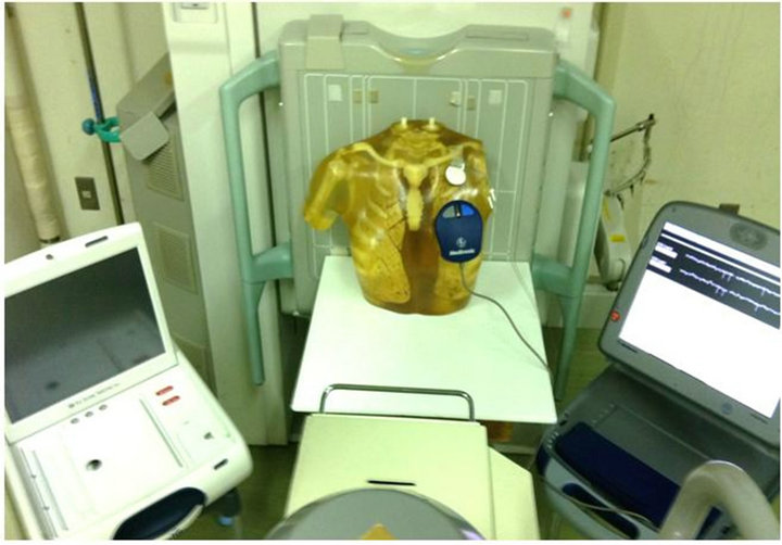
Figure 1. Oversensing experiment of PM by X-rays of X-ray diagnosis equipment 8 kinds of PMs were used to examine the PM that generates oversensing. Pacemaker was set at lower rate at 60 ppm with minimum sensitivity. TF-6TL-6 (Toshiba medical systems corporation) was use as a plain X-ray photography method and the PM on the clavicle of the chest phantom (Kyoto Kagaku, Japan) was irradiated. Irradiation conditions were as follows: Source-surface distance (SSD): 1 m; tube voltage: 120 kV; tube current: 200 mA.
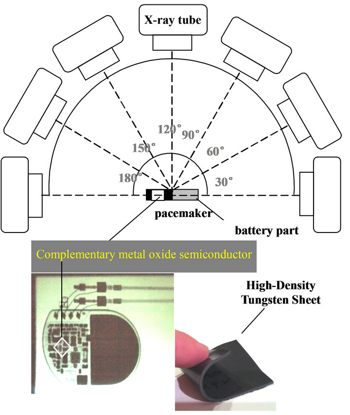
Figure 2. Direction dependency of X irradiation of PM and High-Density Tungsten Sheet.
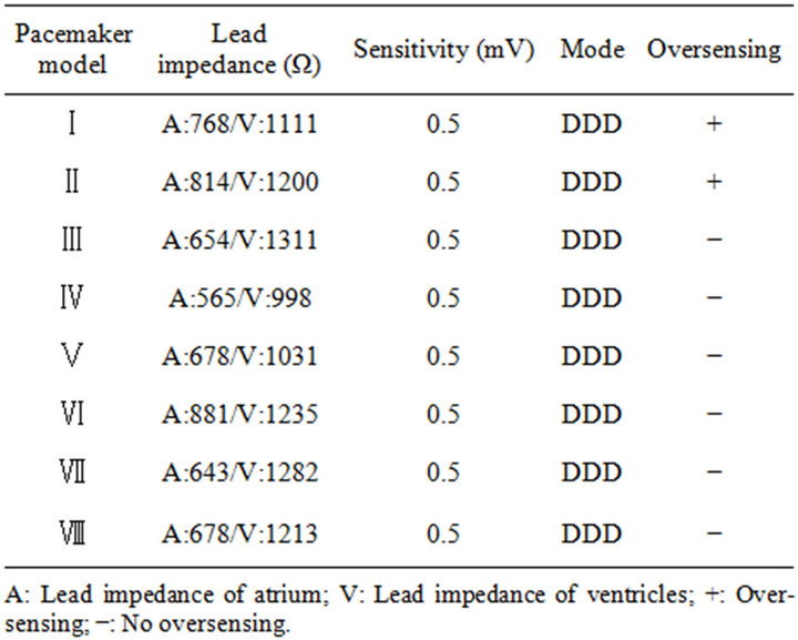
Table 1. Oversensing generation experiment of PM, 2 (I, II) out of 8 (I-VIII) models of PM generated oversensing.
The limit of the lengthened irradiation time becomes equal to the cumulative dose (mA × sec) of the usual irradiation conditions.
2.4. Experiment of Oversensing Suppression by Pacemaker Protection
Plain X-ray photography was conducted with a 1 mm High-density Tungsten Sheet placed on PM under the same irradiation conditions of (2) and (3).
3. Result
3.1. Oversensing Generation Experiment of PM
As is shown in Table 1, oversensing occurred in 2 (I, II) out of 8 (I-VIII) kinds of PMs. Atrial pacing (hereafter, AP) and ventricular pacing (hereafter, VP) of PMs that didn’t generate oversensing were normally functioning (Figure 3).
As is shown in Figure 4, AP of the PM (I) which generated oversensing changed to atrial sensing (hereafter, AS). AS is usually displayed only when the self-cardiac beats from the heart are perceived. However, AS in this experiment was caused by oversensing from X-ray. AS stops pacing from PM to an atrium. The normal value of the time from VP to AP in this experiment is 990 msec. However, due to oversensing, the time from VP to AP was 1807 msec.
As is shown in Figure 5, AP was no longer displayed
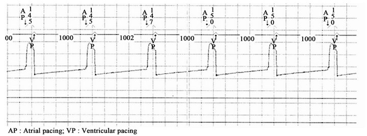
Figure 3. Result of oversensing generation experiment of PM (III-VIII), Atrial pacing (AP) and ventricular pacing (VP) of PM which didn’t generate oversensing were normal.
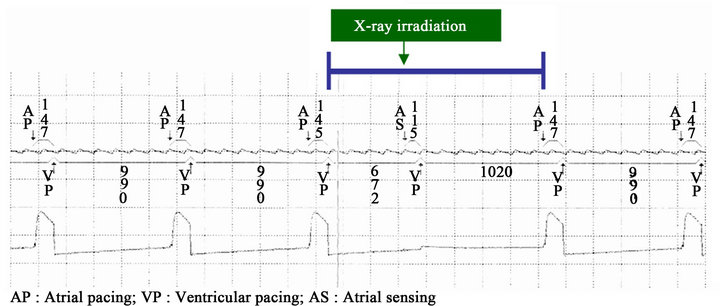
Figure 4. Result of oversensing generation experiment of PM (I).
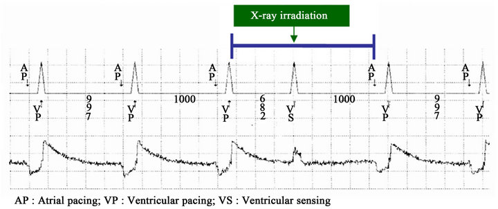
Figure 5. Result of oversensing generation experiment of PM (II).
with PM (II) which generated oversensing, and VP changed to ventricular sensing (hereafter, VS). VS is usually displayed only when the self-cardiac beats from the heart are perceived. However, VS in this experiment was caused by oversensing from X-ray. VS stops pacing from PM to the ventricle. The normal value of the time from VP to AP in this experiment is 997 - 1000 msec. However, due to oversensing, the time from VP to AP was 1682 msec.
3.2. X-Ray Irradiation Direction Dependency of PM
As is shown in Figure 6, PM is most likely to occur oversensing when X ray is irradiated perpendicularly [PM (I) 90˚, PM (II) 90˚]. Oversensing is less likely happen when X ray is irradiated obliquely [PM (II) 120˚, PM (II) 60˚, PM (I) 60˚, PM (I) 60˚, PM (I) 150˚, PM (II) 150˚, PM (I) 30˚, PM (II) 30˚].
However, PM (I, II) which was irradiated at right angles (0˚, 180˚) did not generate oversensing. In this experiment, oversensing was more likely to occur at more higher tube voltage and higher tube current.
PM (I) with 90˚ started to generate oversensing at 120 kV/50 mA, 110 kV/64 mA, 100 kV/80 mA, 90 kV/100 mA, 80 kV/160 mA, and 70 kV/200 mA. PM (II) with 90˚ started to generate oversensing at 120 kV/50 mA, 110 kV/80 mA, 100 kV/80 mA, 90 kV/100 mA, 80 kV/125 mA, and 70 kV/160 mA. Both PM (I) with 90˚ and PM (II) with 90˚ don’t generate oversensing under 120 kV/40 mA. Also, if the irradiation conditions and the angle of plain X-ray photography are plotted on this figure, generating of oversensing of PM can be expected.
3.3. PM Irradiation Experiment of Plain X-Ray Photography
As is shown in Table 2, 2 models (I, II) of the pacemaker generated oversensing under the irradiation conditions of (cervical spine, thoracic spine, lateral thoracic spine, rib, shoulder joint, collarbone, humerus, and chest). PMs (III-VIII) didn’t generate oversensing. PMs (I-II) suppressed oversensing generation in the experiment in which tube voltage was lowered to 100 mA (cervical spine, thoracic spine, lateral thoracic spine, rib, shoulder joint, collarbone, and humerus). However, it was impossible to suppress the oversensing of the chest. But in the experiment in which High-Density Tungsten Sheet was placed on PM, it was possible to suppress oversensing under any irradiation conditions.
4. Discussion
In this experiment, oversensing occurred in 2 out of 8 models of PM, which indicates that the mechanism of oversensing generation of PM is model-dependent on X-ray. PM is originally equipped with a Complementary Metal Oxide Semiconductor (C-MOS) circuit which is considered to be a cause of oversensing. A semiconductor is used for C-MOS circuit. A pair of a positive hole and a negative electron is generated once X-rays are irradiated onto the PN junction (i.e., the junction between a p-type semiconductor and an n-type semiconductor) of a semiconductor. This occurrence mechanism generates extra electricity at the PN junction and induces oversensing. In this experiment, oversensing does not occur unless X-ray intensity (kV × mA) exceeds the threshold (Table 2).
Due to the change of angle of X-ray irradiation, the definition of occurrence of oversensing and irradiation conditions (kV × mA) have changed (Figure 6). Thus, PM has a direction dependency on X-ray. Oversensing occurred with the most low irradiation conditions (kV × mA) when PM was irradiated at 90˚ (vertically to CMOS semiconductor). The acuter the angle of irradiation is (α > 90˚ < α), the higher the irradiation conditions (kV × mA) at which oversensing start to occur. The cause is attributable to the structure of PM, which is covered with titanium alloy, and the inside of which is densely-packed with a lithium iodine battery, precision circuits and connectors. These materials are considered to become factors to cause the decrease of X-rays depending on the difference of X-ray angles. The angles of the plain X-ray irradiation in a hospital vary with the body parts or conditions of patients. Also, the angle of PM that is implanted in a patient’s body is not uniform. As such, it can be considered that oversensing occurs when several conditions (direction and intensity of X-ray) are synchronized. Therefore, once the irradiation angle and irradiation conditions (kV × mA) are available, oversensing is predictable to some extent. Oversensing of PM can be predicted if conditions of plain X-ray photography (cervical spine, thoracic spine, lateral thoracic spine, rib, shoulder joint, collarbone, humerus, and chest) and angle are plotted into Figure 6. For example, the gray area indicates the irradiation conditions of PM (I) 90˚ in which oversensing is less likely to occur. In fact, oversensing did not occur under humerus irradiation conditions in the actual experiment. Moreover, oversensing generation was suppressed in most of the X-ray photography by lowering tube current down to 100 mA. According to Figure 6, it can be predicted that oversensing won’t occur until the tube voltage becomes 90 kV at 100 mA. In addition, PM (II) 60˚ and 120˚ on Figure 6 indicate that oversensing won’t occur until the tube voltage becomes 100 kV at 100 mA. As just described, a certain degree of oversensing can be predicted by matching with irradiation angles of each PM.
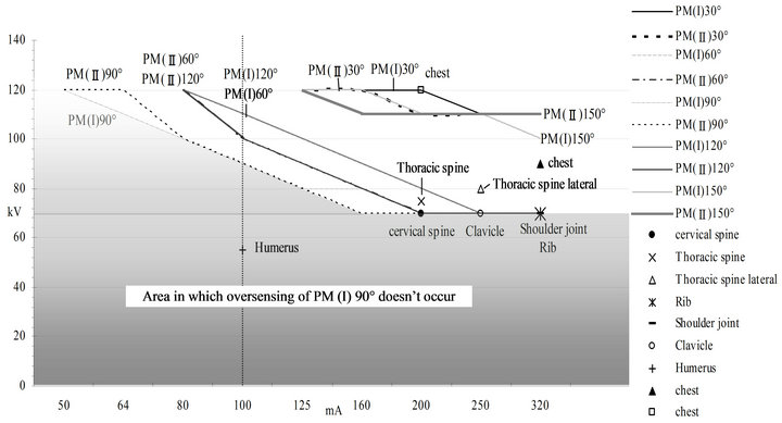
Figure 6. Result of the experiment of direction dependency of X irradiation of PM and irradiation conditions of plain X-ray photograph.
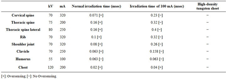
Table 2. PM (I, II) irradiation experiment of plain X-ray photography.
Oversensing could not be suppressed only for a chest X-ray. Figure 6 indicates that oversensing can occur when tube voltage is high at 120 kV unless tube current is set low at 40 mA. Moreover, if a chest X-ray is conducted at 40 mA, the irradiation time becomes longer in order to obtain the same cumulative dose (mA × msec). Shorter irradiation time is desired since a chest X-ray produces blur to angiopneumography due to heat beats. Therefore, a chest X-ray is not recommendable at 40 mA. For the other types of plain X-ray photography, heart beats don’t cause any problem, which means longer irradiation time won’t be a problem at all. As is shown in Table 2, 1 mm High-Density Tungsten Sheet which was put on PM suppressed oversensing during a chest X-ray. It can be considered that X-rays were attenuated to the lower than the threshold that could cause oversensing while they passed through High-Density Tungsten Sheet. The reason for using High-Density Tungsten Sheet was that it has a lead equivalence of from 1.1 mmPb to 1.2 mmPb per 1 mm thickness and has a higher shielding ability than lead. In addition, it was because the sheet is flexible and can easily be cut out with scissors for the size and the form of a PM implanted inside of the body and can minimize the shielding part and maximize the interpretation-feasible area.
We had three limitations in this study. The first one was that we had not enough PMs. Second, we tried only one kind of thickness of High-Density Tungsten Sheet. Third, we had a difficulty to predict the irradiation angle because the angle of PM implanted in a patient was unclear.
5. Conclusions
This time we used several kinds of PMs to conduct the experiment of oversensing that was caused by X-ray from X-ray diagnostic device and examined X-ray direction dependency as well as oversensing suppression of PMs.
As a result, two (I, II) out of eight models were confirmed with oversensing, which revealed that PM has a machine dependency. Due to the change of angle of Xray irradiation, the definition of occurrence of oversensing and irradiation conditions (kV × mA) have changed (Figure 6). Thus, PM has a direction dependency on X-ray. In plain X-ray photography, oversensing was confirmed under the irradiation conditions of (cervical spine, thoracic spine, lateral thoracic spine, rib, shoulder joint, collarbone, humerus, and chest). It was found out from this experiment that oversensing would occur when some conditions (X-irradiation direction, X-irradiation intensity) are met. Our findings will help to predict oversensing generation of plain X-ray photography and suppress oversensing. Oversensing can be suppressed in most of the radiography by lowering tube current to 100 mA, but 1.0 mm High-Density Tungsten Sheet must be put on PM in high tube voltage radiography. From the results of the experiment so far, it is evident that oversensing starts to occur in the lower tube current with the higher tube voltage and in the higher tube current with the lower tube voltage.
Oversensing of PM may cause harmful effects on human body such as bradyarrhythmia and resultant vertigo or fainting [1-12]. I really would like to expect that the data of this experiment would be of some help to the safety of plain X-ray photography.
REFERENCES
- C. H. McCollough, J. Zhang, A. N. Primak, W. J. Clement and J. R. Buysman, “Effects of CT Irradiation on Implantable Cardiac Rhythm Management Devices,” Radiology, Vol. 243, No. 3, 2007, pp. 766-774. doi:10.1148/radiol.2433060993
- O. Nakamura, G. Nakaya, S. Ogashiwa, A. Hashimoto and M. Kondou, “Experimental Study of the Influence on Pacemakers of X-Rays from Angiocardiography Equipment,” Japanese Journal of Radiological Technology, Vol. 64, No. 3, 2008, pp. 335-341. doi:10.6009/jjrt.64.335
- N. Umezawa, M. Hirose and T. Shinbo, “Verification of Irradiation Conditions of X-Rays That Influence Implantable Cardiac Pacemakers,” Japanese Journal of Radiological Technology, Vol. 64, No. 7, 2008, pp. 795-804. doi:10.6009/jjrt.64.795
- N. Oda, H. Nakajima, H. Abe, S. Koyama and S. Kakeda, “Effect of Diagnostic X-Rays of Implantable Cardiac Pacemakers and Implantable Cardioverter Defibrillators, and It’S Management,” Japanese Journal of Radiological Technology, Vol. 64, No. 7, 2005, pp. 805-813. doi:10.6009/jjrt.64.805
- S. Yamaji, S. Imai and F. Saito, “Does High-Power Computed Tomography Scanning Equipment Affect the Operation of Pacemakers?” Circulation Journal, Vol. 70, No. 2, 2006, pp. 190-197. doi:10.1253/circj.70.190
- T. Ushijima, Y. Yamao, N. Nagasawa, M. Matsuzuki and T. Sasou, “Partial Electrical Reset of CT Irradiation on Implantable Cardiac Devices: Relationship between Reset and Tube Voltage, Tube Current, and Rotation Time,” Japanese Journal of Radiological Technology, Vol. 67, No. 6, 2011, pp. 648-653. doi:10.6009/jjrt.67.648
- N. G. Blamires and J. Myatt, “X-Ray Effects on Pacemaker Type Circuits,” Pacing and Clinical Electrophysiology, Vol. 5, No. 2, 1982, pp. 151-155. doi:10.1111/j.1540-8159.1982.tb02206.x
- M. Niehaus and J. Tebbenjohanns, “Electromagnetic Interference in Patients with Implanted Pacemakers or Cardioverter-Defibrillators,” Heart, Vol. 86, No. 3, 2001, pp. 246-248.
- Pharmaceuticals and Medical Devices Safety Information, No. 213, 2005, pp. 3-4.
- Pharmaceuticals and Medical Devices Safety Information, No. 221, 2006, pp. 12-15.
- Pharmaceuticals and Medical Devices Safety Information, No. 263, 2009, pp. 34-36.
- D. L. Hayes, P. J. Wang, D. W. Reynolds, M. Estes 3rd, J. L. Griffith, et al., “Interference with Cardiac Pacemakers by Cellular Telephones,” The New England Journal of Medicine, Vol. 336, 1997, pp. 1473-1479. doi:10.1056/NEJM199705223362101
NOTES
*Corresponding author.