World Journal of Engineering and Technology
Vol.06 No.04(2018), Article ID:87872,13 pages
10.4236/wjet.2018.64050
PSC Bridge Subjected to Combined Post Tension and Post Compression―A Case Study
Sujith Shetty Sundar1*, Suraj Sathyanrayana Rao2
1Department of Civil Engineering, MSRIT, Bengaluru, India
2Department of Civil Engineering, UVCE, Bengaluru, India

Copyright © 2018 by authors and Scientific Research Publishing Inc.
This work is licensed under the Creative Commons Attribution International License (CC BY 4.0).
http://creativecommons.org/licenses/by/4.0/


Received: August 26, 2018; Accepted: October 16, 2018; Published: October 19, 2018
ABSTRACT
Starting from the ideas of Conventional Post Tensioning we present a heuristic argument of advantages of combined actions of post compression along with post tensioned technique for a PSC member through a Design Example. Our aim was to assess the characterization of a pre stressed member if it was to be under the Load effects of post compressing a bar with post tensioned method through hydraulic jacks as the reinforcements in the tensioned zone of conventional PSC bridge were to be compressed in order to induce internal tensile stress similar to internal compressive stresses developed due to conventional post tensioned design. The results ultimately concluded that post compressing a Slender bar by a pre stressing force in the compression zone by a value equal to 0.1 - 0.7 times the pre stressing force in the tension zone would eventually lead to cancelling out of tensile and compressive stresses, thereby forming the desired section which is comparatively smaller in size but can account for sustainability. The anchorage at the top end was provided by special slender steel rods to eliminate the compressive stresses. All the dead loads were counteracted by the action of prestress and the bridge section was able to carry only live load which is deduced through examples in the article.
Keywords:
Combined Post Tension and Post Compression, Prestress Concrete, Design of Bridges

1. Introduction
Prestressing is the establishment of internal stresses in a structure or system to increase the durability of its performance. In pre stressed concrete the induced stresses are in such a magnitude that they can counteract on the applied external loads. The prestress developed by the means of hydraulic jacks introduces compressive stress below the neutral axis and thus gets back the structure into its original shape once it gets acted upon by the external loads [1] [2] [3] [4] .
1) Pre tensioning: In which the tendons are tensioned before the concrete is placed, tendons are temporarily anchored and tensioned and the pre stress is transferred to the concrete after it is hardened.
2) Post tensioning: In which the tendon is tensioned after the concrete has hardened.
Tendons are held up in holes provided with sheaths at different known locations along the section and are tensioned using hydraulic jacks once the member is hardened of concrete [5] [6] .
A different process of pre stressing which is known by the name of post compression was used in early 20th century by Kurt Billig [7] . Post-compressing a structure has the same principle of post-tensioning a structure with exception of stresses developed as a post compressed reinforcement experiences axial tension. Concepts of post compressing system in concrete structures were developed theoretically with a practical example in the early 1970s by Reiffenstuhl [7] [8] [9] , a German civil engineer as in 1977 a 76 m Single span bridge for road traffic was built in Upper Austria by him. The main feature of this pre stressed Concrete Bridge is the use of a new structural element; that of post compressed reinforcement. It consists of high strength steel bars of round cross section which at first lies unbound in sheaths. After stressing of conventional tendons in post tensioning, the high strength steel tendons are provided above neutral axis with eccentricities and are stressed in compression by means of hydraulic jacks and then anchored in the structure and grouted. One of the advantages out of many is that post compressing a slender bar would ultimately lead to the more economically optimized section as compared to that of the section that was obtained during design of conventional post tensioned process and would eventually act as an economical buffer in long span projects. The aim of this paper is to establish the fact of effectiveness of inculcating post compression along with conventional post tensioning for long span PSC Structures by analyzing a given design example. Mathematical expressions were deducted by analyzing concepts of post compression along with certain ideas from previously published research articles [10] [11] [12] .
2. Background
Previous research on the use of advancement in pre stressed concrete in long span precast structures is limited. Further, to the best of the authors knowledge, only few research exists on the efforts of advancement of pre stressed concrete in terms of using tendons to stress at its compressed region. It can be noted from the research works of T. M. Yoo, J. H. Doh, H. Guan [13] that The addition of the pre stressing force in a deep beam increases the shear capacity of the beam counteracting the effect of the web opening and research on high strength concrete deep beams with various openings remains relatively unexplored and needs more focused research in the future. A research report published by Vakas K. Rahmani, A. R. Mundhada [14] reveals that from spans 9 m to 12 m, pre stressed Concrete flat slab becomes economical and as the span increases its economic efficiency increases and also in addition pre stressing delivers a structure that is better from limit state of serviceability and durability point of view. A Notable catch in the conventional method of pre stressing is that even though it’s quite evident the methods of prestressing have far better results in the durability of structures compared to RC structures, but there’s not been a quite advancement in increasing the load carrying capacity of PSC structures by decreasing its overall depth. A Research article submitted by Adekunle Philips Adewuyi and Shodolapo Oluyemi [15] Franklin thus weighs in the method of using conventional post tensioning the structure along with a new method known as post compression as from the literature review it was noted that in their study of simple beam, the pre stressing forces in the post tensioned tendons were self-supporting yet being quadratic ally related to eccentricities until the value of 0.7 beyond which the relationship didn’t hold good. Prestressing force ratio and the eccentricity ratio have direct consequences on the eccentricities, as eccentricity reduces with increase in post compression force value. Hence deducing from all these statements we provide an agreement of the use of post compression technique in long span girders by comparing a case study of a conventional PSC Transport Bridge [16] [17] incorporating conventional post tensioned deign and modern post compression design.
3. Mode of Action
The mode of action of the beam subjected to post compressed reinforcement is shown in Figure 1. The upper and the middle beams develop stresses that are conventional by the introduction of dead load (self-weight) and traffic load in first beam and by post tensioning by hydraulic jacks in middle one. The lower beam is armed with post compressed reinforcement. The compressive forces are introduced into the beam by end anchorage (Figure 2 and Figure 3) produces tensile stresses uniformly distributed over the depth. The forces of deflection are upward and they produce the same stresses as that of post tensioning. Adequate use of both post-tensioned and post compressed reinforcement leads to a large bending moment counteracting external loads, with only a small portion of normal force due to pre stressing. By means of the post compressed reinforcement it is possible almost to double the bending Moment capacity of a cross section of ordinary pre stressed concrete which is illustrated briefly.
4. Objective
The case study deals with the design and analysis of a PSC T-beam bridge, which provides access between two important villages using conventional
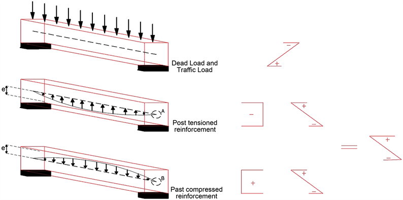
Figure 1. Showing the mode of action of pre stressed structure when subjected to dead load, traffic load, post tensioning and post compression (courtesy: IABSE Structures C-12/80 IABSE PERIODICA 1/1980).
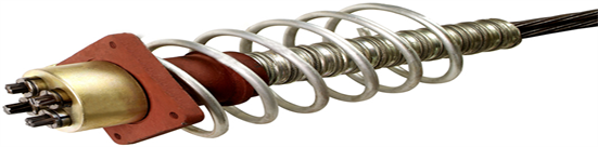
Figure 2. Providing a glimpse of conventional anchorage in post tensioning.
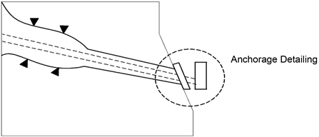
Figure 3. Providing a glimpse of anchorage for post compressed bars.
post-tensioning methods and a non-conventional post compressing methods. The proposed site for bridge construction is shown in Figure 4 and the details of bridge as are of Table 1.
5. Methodology (Materials and Process Involved)
5.1. Anchorage
The process for anchorage for post compressed slender bar is as shown in Figure 5.

Figure 4. Proposed PSC bridge location.

Table 1. Salient features of PSC bridge.
Single anchorage of each compressed bar was chosen for the reason of easy access. The compressed bar (diameter 36 mm S 1080/1320) transfers its force by means of a thread and nut assembly into the anchor plate. The plate is fixed in the beam’s concrete with the help of 8 button headed cold-drawn stressing steel wires (diameter 12.2 mm, S 1370/1570 with undulated ends). The anchorages of the post-compressed bars should be given care as they shouldn’t force the concrete in its vicinity to move out and this can be done easily, e.g. By setting the anchorages of the bars between anchorages of tendons.
5.2. Flexural Analysis in Service
Analysis of a PSC Structure forms the critical part in the getting to know their different characteristics under the action of critical loads. The most important analysis for a design can be made in Flexure as well as Shear, although Flexural Analysis forms the crucial stage to introspect the durability and overturning resistance of a PSC structure. In our analysis much of the consideration is given in determination in stress distribution in PSC beam under the serviceability condition to note down its moment carrying capacity. A rational pre stressing force for both approximation (post-tensioning and post compression) is deduced considering the independent and time dependent loses at transfer and service conditions. Limits are set on the deformation control as the span/depth ratios and level of pre stress are narrowed down. The concrete stresses that re developed during transfer and serviceability condition are also restricted in order to control

Figure 5. Detailing of end anchorage of post compressed rebar.
the longitudinal cracks and creep formation. In order to minimize the inelastic deformation of the beam there is also a limit on the value of effective prestress after the time independent loses have occurred.
Consider an simply supported isometric beam of length L width B and depth H which has been reinforced with post tensioned tendons and post compressed high strength steel bars at eccentricities et and ec at bottom and top from the neutral axis respectively as shown in Figure 6. The beam is subjected to various internal and external loads such as the self-weight of the beam (gk), superimposed dead load (DL), superimposed live load (LL). The cross sectional area of the beam is denoted by Ac and the sectional modulus at top and bottom of the surface is denoted as ZTOP and ZBOT respectively. The notation Cg refers to centroid of the concrete section and CT and CB denotes the centriods of reinforcement at post compression and post tensioned regions respectively.
The stresses at the extreme top and bottom fibres at transfer are
(1)
(2)
The stresses in the extreme top and bottom fibres of the concrete section at service are given by:
(3)
(4)
where µ and α are residual pre stress ratios after time dependent losses have taken place in relation to the pre stressing forces PT and PB.
MT and MS are the maximum bending moments at transfer and service respectively
(5)
Combination of Equations (1) and (3) yields:
(6)
where .
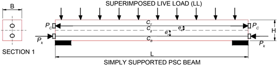
Figure 6. Pre stressed concrete beam reinforced with straight post-tensioned and post-compressed tendons.
A similar operation on Equations (2) and (4) yields
(7)
= bottom and top fibre stress, respectively at transfer stage;
= bottom and top fibre stress, respectively at service stage;
= allowable compressive stress at transfer and service stage, respectively;
= allowable flexural tensile stress at transfer and service stage respectively.
Also the top and bottom elastic section moduli can be obtained from Equations (6) and (7), respectively as follows
(8a)
(8b)
Also, the following general assumptions may be considered for a more reasonable approximation:
(9a)
(9b)
If and , and Equations (9a) and (9b) are applied to Equations (6) and (7), the top andbottom elastic section moduli can be obtained as
(10a)
(10b)
5.3. General Assumptions and Sign Conventions
The analysis part of the design of PSC Bridge is made considering various assumptions as well as sign conventions, as the stress distribution along the length of the beam is considered to be linear in nature and both the concrete and steel tendons are assumed to act as elastic members in the vicinity of working stresses under the action of loading. The effects of creep and shrinkage are considered to develop after the member is subjected to constant sustained load. Sagging moments developed due to the action of compressive stresses are considered to be positive while on the other hand hogging moments due to tensile stresses are considered to be negative in nature. Eccentricity values which are above the centroid are deemed positive (post tensioned process) while those below the centroid are deemed negative (post compression technique).
The dead load carried by the girder and member shall consists of weight of the super structure which is supported wholly or in part by the girder or member including its own weight.
The design live load consists of standard wheeled or tracked class AA vehicle loading (according to Indian Road Congress Specifications) with a provision for impact or dynamic action shall be made by an increment of the live load by an impact allowance expressed as a fraction or a percentage of the applied load. In our case it is assumed to be 10%.
6. Design of the PSC Structure
Post Tension Design
The Design of the PSC Bridge was done through CSI Bridge 2017 versioned software. In order to account for variability, the shape of the bridge was considered to be parabolic in nature with sloping at mid section from both left and right ends [5] [6] . The PSC Bridge consisted of two abutments at the ends for support and 3 columns with bent cap at center of the span for bearing purposes (Figure 7(a) and Figure 7(b) and Figure 8). The designed bridge was checked on safety for earthquake and wind load vibrations and respective design response spectrum was also noted down. The Horizontal Ultimate moments and the Vertical Shear forces were also noted down (Figures 9-11).
 (a)
(a)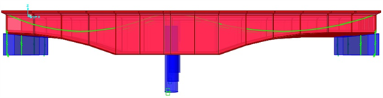 (b)
(b)
Figure 7. (a) Extruded view of the PSC bridge. (b) Extruded view of the PSC bridge showing abutments and column with bent cap.

Figure 8. Deformed shape of the bridge under the action of loading.
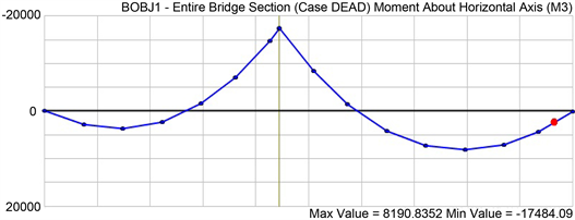
Figure 9. Graph showing ultimate horizontal moment under the action of loading.
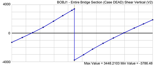
Figure 10. Graph showing ultimate vertical shear force under the action of loading.
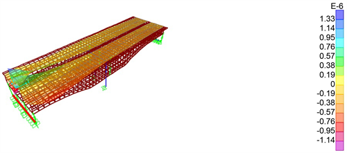
Figure 11. Extruded view showing the analysed influence lines along the span of the bridge.
Through Analysis it was noted that the area of the steel required was found to be
The respective section moduli for the bridge was found to be
Comparing these values theoretically with post compression design we get the values as follows
Additional moment of 2 M∙nm is added as extra moment as a product of truck load during analysis, thus
4 conditions to check for minimum section
And from other conditions considering the loss ratios (µ and α) and prestressing ratios (λ and β) we get,
where, µ and α = 0.9 and λ = 0.5, β = 2. Considering fti = −1 N/mm2 and fts = 0 N/mm2.
Hence here
It can be seen that relatively both the section moduli in case of combined action of post compressed design were less that to the traditional post tensioned design even though the moment induced were increased significantly. Also the stresses developed were far lesser and are shown as below.
Stress developed in section
7. Discussion
Through analysis and verifying the results it can be noted that for practical applications the prestress ratio should lie in the range of 0.1 ≤ λ ≤ 0.8 as it was also found out that the prestressing ratio are independent of the eccentricity ratio (β) in case of post compression technique whereas in conventional post tensioned method the eccentricity ratio was found to be viable in the range 0 ≤ β ≤ 4. Figure 12 and Figure 13 were plotted to find the variation in the action of prestress in both conventional post tensioned design (Figure 12) and combined post compression and post tensioned design (Figure 13). Careful look into the graph provides the information that the variation is of the parabolic nature up to prestressing ratio value of 0.7 and becomes linear above it for both cases. Also the prestressing variation is quite less in post compressioned design when compared to the values obtained in conventional design.
8. Results and Conclusion
The Bridge has been designed as a PSC Bridge using both Conventional post-tensioned and post-compressed methods. And comparing the results, the following conclusions can be drawn out.
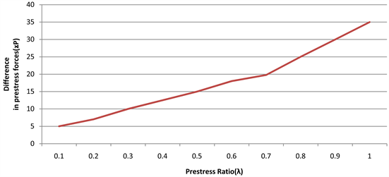
Figure 12. Graph representing the variation of prestress with prestress ratio (λ) on horizontal axis.
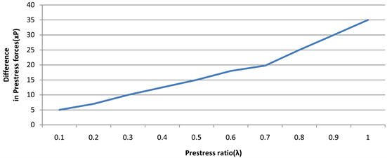
Figure 13. Graph representing the variation of prestress with eccentricity ratio (β) on horizontal axis with post compression design.
The depth of the main girder can be reduced in case of combined action of post compression and post tensioned reinforcements since the section moduli in the former case is comparatively lower when compared with conventional post tensioned design, even though the Horizontal ultimate moment remains the same. There is overall reduction of loading on pile due to combined post tensioning and post compressed reinforcement, as a result.
There is a provision for elimination of one pier by increasing the span (i.e. from 35 m to 70 m) and in turn resulting in 5% - 6% cost reduction. Very suitable and cost effective in case of Long span structures.
It is clearly evident from both graphs (Figure 12 and Figure 13) that the eccentricities in the section decreases as post compressed reinforcement are introduced and in turn the overall depth of the PSC structure can be reduced by an adequate amount.
Conflicts of Interest
The authors declare no conflicts of interest regarding the publication of this paper.
Cite this paper
Sundar, S.S. and Rao, S.S. (2018) PSC Bridge Subjected to Combined Post Tension and Post Compression―A Case Study. World Journal of Engineering and Technology, 6, 767-779. https://doi.org/10.4236/wjet.2018.64050
References
- 1. Nawy, E.G. (1996) Pre Stressed Concrete: A Fundamental Approach. 5th Edition, Prentice Hall, Upper Saddle River.
- 2. Collins, M.P. and Mitchell, D. (1991) Pre Stressed Concrete Structures. Prentice Hall, Upper Saddle River.
- 3. Sriskandan, K. (1989) Prestressed Concrete Road Bridges in Great Britain: A Historical Survey. Proceedings of the Institution of Civil Engineers, Vol. 86, April 1989, 269-302.
- 4. Smyth, W.J.R. (1996) UK Concrete Bridges since 1940. Proceedings of the Institution of Civil Engineers, Vol. 116, August 1996, 432-448. https://doi.org/10.1680/istbu.1996.28752
- 5. Dunker, K.F. and Rabbat, B.G. (1992) Performance of Pre Stressed Concrete Highway Bridges in the United States—The First 40 Years. PCI Journal, 37, 48-64. https://doi.org/10.15554/pcij.05011992.48.64
- 6. Naaman, A.E. and Breen, J.E. (1990) External Prestressing in Bridges. SP 120, American Concrete Institute, Detroit.
- 7. Reiffenstuhl, H. (1978) The Alm Bridge in Austria—The First Bridge in Pre Stressed Concrete with Postcompressed Reinforcement. Notes 74, Federation Internationale de la Precontrainte.
- 8. Reiffenstuhl, H. (1982) Das Vorspannen von Bewehrungen auf Druck; Grundsatzliches und Anwendungsmoglichkeiten. Beton- und Stahlbetonbau, 77, 69-73. https://doi.org/10.1002/best.198200100
- 9. Reiffenstuhl, H. (1989) The Pedestrian Bridge over the Rupert-Mayer-Straβe in Munich: Pre Stressed Concrete Structure with Pre-Compressed Reinforcement. Bauingenieur, 64, 159-163.
- 10. Indian Road Congress Code 6-2010 for Bridge Construction.
- 11. IS 1343-1980 Indian Standard Code of Practice for Pre Stress Concrete.
- 12. IS 456-1980 Indian Standard Code of Practice for Reinforced Concrete.
- 13. Yoo, T.M., Doh J.H., Guan, H. and Fragomeni, S. (2007) Experimental Work on Reinforced and Prestressed Concrete Deep Beams with Various Web Openings. https://www.researchgate.net/directory/publications
- 14. Rahmani, K. and Mundhada, A.R. (2013) Comparative Study of RCC and Prestressed Concrete Flat Slabs Vakas. International Journal of Modern Engineering Research, 3, 1727-1730.
- 15. Adewuyi, A.P. and Franklin, S.O. (2011) Analytical Investigation of Prestressed Concrete Structures Incorporating Combined Post-Tensioned and Post-Compressed Reinforcements. Journal of Engineering and Applied Sciences, 6, 55-61.
- 16. Klaiber, F.W., Wipf, T.J., Dunker, K.F., Abu-Kishk R.B. and Planck, S.M. (1989) Alternate Method of Bridge Strengthening. Iowa Department of Transportation Project Report HR-302, Engineering Research Institute of Iowa State University, Ames.
- 17. Zheng, W.Z., An, J.B. and Wang, Y. (2002) Research on Design Theory of Tension and Compression Double-Action Prestressed Concrete Structure. China Journal of Highway and Transport, 15, 35-42.