Open Access Library Journal
Vol.02 No.11(2015), Article ID:68819,10 pages
10.4236/oalib.1102008
Dispersion and Growth-Rate Characteristics of a Sinusoidally Corrugated Slow-Wave Structure in Presence of Cylindrical Electron Beam
Maryam Garjasi1, Shahrooz Saviz2
1Central Tehran Branch, Islamic Azad University, Tehran, Iran
2Plasma Physics Research Center, Science and Research Branch, Islamic Azad University, Tehran, Iran

Copyright © 2015 by authors and OALib.
This work is licensed under the Creative Commons Attribution International License (CC BY).
http://creativecommons.org/licenses/by/4.0/


Received 20 October 2015; accepted 4 November 2015; published 11 November 2015

ABSTRACT
A theory of relativistic traveling wave tube (RTWT) with magnetized cold plasma-filled corrugated waveguide with solid electron beam is given. The entire system influenced a strong longitudinal magnetic field that magnetized plasma and electron beam. The characteristic of the dispersion relation is obtained by numerical solutions. The effect of electron beam density, corrugated period, waveguide radius on the dispersion relation and growth rate is analyzed. Some useful results are given.
Keywords:
RTWT, Solid Electron Beam, Cold Plasma, Dispersion Relation, Growth Rate
Subject Areas: Applied Physics, Theoretical Physics

1. Introduction
Relativistic travelling wave tube (RTWT) is an important high-power microwave (HPM) apparatus which has been developed in the past 20 years [1] - [3] . Pierce and co-workers [4] - [6] employed the coupled-wave analysis in their pioneering work. The analysis of TWT is improved by using linear theories based on the Maxwell’s equations in a sheath helix [7] [8] . The coupled-wave Pierce theory recovers the near-resonant limit. Both coupled- wave and field theories of TWT have discussed in [9] . Freund and coworkers developed the field theories of beam-loaded helix TWTs for tape helix model. Freund and coworkers [8] have described the numerical comparison between the complete dispersion equation and the Pierce model in helix TWT and shown that the coupled- wave theory breaks down for sufficiently high currents. The complete field theory is more exact than the coupled-wave theory. In TWT, sinusoidal corrugated slow wave structure (SWS) is used to reduce the phase velocity of the electromagnetic wave to synchronize it with the electron beam velocity, so that a strong interaction between the two can take place [10] [11] . TWT is extensively applied in satellite and airborne communications, radar, particle accelerators, cyclotron resonance and electronic warfare system. The plasma injection to TWT has been studied recently which can increase the growth rate and improve the quality of transmission of electron beam. We investigate the effect of cold plasma and electron beam on the growth rate [12] - [17] . It is shown that the plasma has different behaviors in different density limits. On the other hand, it is shown that in the strong magnetic field limit, the maximum growth rate and frequency of all modes are constant at different values of cyclotron frequency and beam energy.
An analytical and numerical study is made on the dispersion properties of a cylindrical waveguide filled with plasma. An electron beam and static external magnetic field are considered as the mechanisms for controlling the field attenuation and possible stability of the waveguide [23] - [27] .
In this paper, a RTWT with magnetized cold plasma-filled corrugated waveguide with solid electron beam is studied. The dispersion relation of corrugated waveguide is derived from a solution of the field equations. By numerical computation, the dispersion characteristics of the RTWT are analyzed in detail in different cases of various geometric parameters of slow wave structure.
In Section 2, the physical model of the RTWT filled with cold is established in an infinite longitudinal magnetic field. In Section 3, the dispersion relation of the RTWT is derived. In Section 4, the dispersion characteristics of the RTWT are analyzed by numerical computation.
2. Physical Model
The analysis presented in this paper is based on the SWS shown in Figure 1. The SWS reduces speed of the wave is a sinusoidal cylindrical waveguide that consists of an axially symmetric. The speed wave is reduced after collision with wave guide reaching the speed of the electron beam (synchronism), so the wave is amplified.
 (1)
(1)
 (2)
(2)
Cylindrical waveguide whose wall radius , varies sinusoidal according to the relation (1), h is the corrugation amplitude,
  is the corrugation wave number, and
  is the length of the corrugation period,
  is the waveguide radius and
  is the axial number wave.
A finite solid relativistic electron beam with density  and radius
  goes through the cylindrical waveguide, which is loaded completely with a cold, uniform and collisionless plasma of density
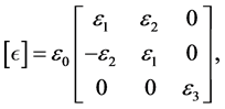
 . The entire system is immersed in a strong, longitudinal magnetic field, which magnetizes both the beam and the plasma. Because dielectric constant is an anisotropic so it will be a tensor. In the beam-plasma case in a linearized scheme, the dielectric tensor, in cylindrical coordinates, may be given by:
 (3)
(3)

Figure 1. Slow wave structure and solid electron beam model of a plasma-filled relativistic travelling wave tube.
We assume that  is very strong that
  and
and  is negligibly small.
 (4)
(4)
Here,  is the plasma frequency,
  is the beam frequency, ω is the angular frequency of the electromagnetic wave,
  is the electron beam energy, v is the velocity of the beam, and K is the Boltzmann constant.
3. Dispersion Equation
In the above physical model, its Maxwell equations can be written as:
 (5)
(5)
 (6)
(6)
 (7)
(7)
 (8)
(8)
Suppose that every variable can be regarded as:
 (9)
(9)
From Equations (5) and (6), we can obtain:
 (10)
(10)
 (11)
(11)
Now Substituting Equation (4) into Equation (11), we have:
 (12)
(12)
From Equation (10), we have:
 (13)
(13)
Substituting Equation (4) into Equation (13), we obtain:
 (14)
(14)
From Equations (11) and (14), the wave equation is obtained in the area of plasma-beam as follows:
 (15)
(15)
 (16)
(16)
 (17)
(17)
 (18)
(18)
We investigate ground state (n = 0) to solve the equation. Substituting Equation (17) into Equation (15), we have:
 (19)
(19)
 (20)
(20)
 (21)
(21)
The field components must satisfy the following continuity equations (first boundary condition):


As a result, the field components are obtained as follows:

where
 .
.
At the perfectly conducting corrugated waveguide surface (second boundary condition), the tangential electric field must be zero,
 (22)
(22)
Substituting Equations (17), (18) and (19) into Equation (22), we investigate second boundary condition in ground state (n = 0) to achieve the dispersion equation.
 (23)
(23)
Using the factorization of Equation (23) and substituting  and
and , we obtain:
 (24)
(24)
 (25)
(25)
A is a vector with element  and D is a matrix with element
 . With the help of derivative of Bessel functions and substituting Equation (1), the dispersion relation can be obtained and written as [18] - [22] .
 (26)
(26)
4. Numerical Result and Discussion
The analysis of the dispersion relation is obtained by Equation (26). First, we consider the dispersion analysis in the absence of the electron beam.
Figure 2 shows the variation of normalized frequency Re  versus wave number
  for several values of the corrugation periods
 . As seen in Figure 3, the effect of
  increases the frequency.
The effect of waveguide radius on the frequency of wave as a function of  is shown in Figure 4. As illustrated in this figure, the frequency decreases by increasing the waveguide radius. The phase velocity of the system decreases by increasing the radius. It maybe cause to the wave exit from the resonant condition.
Now, we consider the analysis of the growth rate in the presence of the electron beam.
It is clear that from Figure 5, the growth rate increases by increasing the corrugation period. This increasing in the corrugation period helps wave to include in the resonant condition and finally increases the growth rate.
As seen in Figure 6, the growth rate decreases by increasing the . The waveguide radius has the most important role in the determination of wave phase velocity. According to Figure 4, it seems that the phase velocity decreases by increasing the radius and as seem in Figure 6 the growth rate decreases by increasing the radius. By decreasing the phase velocity the wave exits from resonant condition.
The effect of the plasma density on the growth rate as a function of the wave number is shown in Figure 7. It is clear that in this frequency range the effect of plasma density decreases the growth rate of the system.
It is clear that from Figure 8 because of bunching effect, the increasing e-beam density increases the growth. As seen from Figure 9, because of the synchronism condition, the effect of  decreases the growth rate.

Figure 2. Variation of normalized frequency Re  with normalized wave number
  for several values of corrugation periods. The chosen parameters are as follows:
 ,
,  , h = 0.7 cm.

Figure 3. Variation of normalized frequency Re  with normalized wave number
  for several values of the plasma density. The chosen parameters are as follows:
 , h = 0.7 cm,
  ,
,  ,
, .
.

Figure 4. Variation of normalized frequency Re  with normalized wave number
  for several values of the waveguide radius. The chosen parameters are as follows:
 , m, h = 0.7 cm,
  ,
,  ,
, .
.

Figure 5. Variation of normalized growth rate Im  with normalized wave number
  for several values of the corrugation period. The chosen parameters are as follows: h = 0.7 cm,
  ,
,  ,
,  ,
,  ,
,  ,
, .
.

Figure 6. Variation of normalized growth rate Im  with normalized wave number
  for several values of the waveguide radius. The chosen parameters are as follows: h = 0.7 cm,
  ,
,  ,
,  ,
,  ,
,  ,
, .
.

Figure 7. Variation of normalized growth rate Im  with normalized wave number
  for several values of the plasma density. The chosen parameters are as follows: h = 0.7 cm,
  ,
,  ,
,  ,
,  ,
,  ,
, .
.

Figure 8. Variation of normalized growth rate Im  with normalized wave number
  for several values of the electron beam density. The chosen parameters are as follows: h = 0.7 cm,
  ,
,  ,
,  ,
,  ,
,  ,
, .
.
5. Conclusions
In this paper, useful results are obtained as follows.
1) The growth rate decreases by increasing the waveguide radius, plasma density and e-beam energy in the presence of the electron beam.
2) In the absence of the electron beam, the frequency increases by increasing the length of the corrugation period and plasma density.

Figure 9. Variation of normalized growth rate Im  with normalized wave number
  for several values of the electron beam energy. The chosen parameters are as follows: h = 0.7 cm,
  ,
,  ,
,  ,
,  ,
,  ,
, .
.
3) The frequency decreases by increasing the waveguide radius in the absence of the electron beam.
4) In the presence of the electron beam, the growth rate increases by increasing the corrugation period and e- beam density.
Cite this paper
Maryam Garjasi,Shahrooz Saviz, (2015) Dispersion and Growth-Rate Characteristics of a Sinusoidally Corrugated Slow-Wave Structure in Presence of Cylindrical Electron Beam. Open Access Library Journal,02,1-10. doi: 10.4236/oalib.1102008
References
- 1. Shiffler, D., Nation, J.A. and Graham, S.K. (1990) A High-Power, Traveling Wave Tube Amplifier. IEEE Transactions on Plasma Science, 18, 546-552.
http://dx.doi.org/10.1109/27.55926 - 2. Nusinovich, G.S., Carmel, Y., Antonsena Jr., T.M., Goebel, D.M. and Santoru, J. (1998) Recent Progress in the Development of Plasma-Filled Traveling-Wave Tubes and Backward-Wave Oscillators. IEEE Transactions on Plasma Science, 26, 628-645.
http://dx.doi.org/10.1109/27.700799 - 3. Kobayashi, S., Antonsen Jr., T.M. and Nusinovich, G.S. (1998) Linear Theory of a Plasma Loaded, Helix Type, Slow Wave Amplifier. IEEE Transactions on Plasma Science, 26, 669-679.
http://dx.doi.org/10.1109/27.700804 - 4. Pierce, J.R. and Field, L.M. (1947) Traveling-Wave Tubes. Proceedings of the IRE, 35, 108-111.
http://dx.doi.org/10.1109/JRPROC.1947.226216 - 5. Pierce, J.R. (1950) Travelling-Wave Tubes, Chapter 3. Van Nostrand Reinhold, New York.
- 6. Pierce, J.R. (1947) Theory of the Beam-Type Traveling-Wave Tube. Proceedings of the IRE, 35, 111-123.
http://dx.doi.org/10.1109/jrproc.1947.226217 - 7. Chu, L.J. and Jackson, J.D. (1948) Field Theory of Traveling-Wave Tubes. Proceedings of the IRE, 36, 853-863.
http://dx.doi.org/10.1109/JRPROC.1948.230932 - 8. Freund, H.P., Vanderplaats, N.R. and Kodis, M.A. (1993) Field Theory of a Traveling Wave Tube Amplifier with a Tape Helix. IEEE Transactions on Plasma Science, 21, 654-668.
http://dx.doi.org/10.1109/27.256785 - 9. Beck, A.H.W. (1958) Space-Charge Waves. Pergamon, New York.
- 10. Brillouin, L. (1953) Wave Propagation in Periodic Structures. Dover, New York.
- 11. Collin, R.E. (1960) Field Theory of Guided Waves. McGraw-Hill, New York.
- 12. Saviz, S. (2014) The Effect of Beam and Plasma Parameters on the Four Modes of Plasma-Loaded Traveling-Wave Tube with Tape Helix. Journal of Theoretical and Applied Physics, 8, 135.
http://dx.doi.org/10.1007/s40094-014-0135-7 - 13. Saviz, S. and Salehizadeh, F. (2014) Plasma Effect in Tape Helix Traveling-Wave Tube. Journal of Theoretical and Applied Physics, 8, 1.
http://dx.doi.org/10.1007/s40094-014-0125-9 - 14. Coaker, B. and Challis, T. (2008) Travelling Wave Tubes, Modern Devices and Contemporary Applications. Microwave Journal, 51, 32-48.
- 15. Saviz, S. and Shahi, F. (2014) Analysis of Axial Electric Field in Thermal Plasma-Loaded Helix Traveling-Wave Tube with Dielectric-Loaded Waveguide. IEEE Transactions on Plasma Science, 42, 917-923.
http://dx.doi.org/10.1109/TPS.2014.2306018 - 16. Zavyalov, M.A., Mitin, L.A., Perevodchikov, V.I., Tskhai, V.N. and Shapiro, A.L. (1994) Powerful Wideband Amplifier Based on Hybrid Plasma-Cavity Slow-Wave Structure. IEEE Transactions on Plasma Science, 22, 600-607.
http://dx.doi.org/10.1109/27.338273 - 17. Saviz, S. (2014) Plasma Thermal Effect on the Growth Rate of the Helix Traveling Wave Tube. IEEE Transactions on Plasma Science, 42, 2023-2029.
http://dx.doi.org/10.1109/TPS.2014.2329996 - 18. Miyamoto, K. (2000) Parameter Sensitivity of ITER Type Experimental Tokamak Reactor toward Compactness. Journal of Plasma and Fusion Research, 76, 166.
- 19. Xie, H.-Q. and Liu, P.-K. (2007) Theoretical Analysis of a Relativistic Travelling Wave Tube Filled with Plasma. The Chinese Physical Society, 16, 766.
- 20. Chen, F.F. (1984) Introduction to Plasma Physics and Controlled Fusion. Plenum Press, New York.
- 21. Krall, N.A. and Trivelpiece, A.W. (1973) Principles of Plasma Physics. McGraw-Hill, New York.
- 22. Goldston, R.J. and Rutherford, P.H. (1995) Introduction to Plasma Physics. Institute of Physics Publishing, Bristol.
http://dx.doi.org/10.1887/075030183X - 23. Abubakirov, E.B. and Konyushkov, A.P. (2010) Peculiarities of Backward-Wave Amplification by Relativistic High- Current Electron Beams. IEEE Transactions on Plasma Science, 38, 1285-1291.
http://dx.doi.org/10.1109/TPS.2010.2043120 - 24. Khalil, S.M. and Mousa, N.M. (2014) Dispersion Characteristics of Plasma-Filled Cylindrical Waveguide. Journal of Theoretical and Applied Physics, 8, 111.
- 25. Babkin, A.L., Chelpanov, V.I., Dubinov, A.E., Dubinov, E.E., Hizhnyakov, A.A., Konovalov, I.V., Komilov, V.G., Selemir, V.D. and Zhdanov, V.S. (1997) Powerful Electron Accelerator “COVCHEG”: Status, Parameters and Physical Experiments. Proceedings of the 11th IEEE International Pulsed Power Conference, Baltimore, 29 June-2 July 1997, 765-769.
- 26. Chelpanov, V.I., Dubinov, A.E., Dubinov, E.E. and Babkin, A.L. (1997) In: 1997 IEEE International Pulsed Power Conference, Digest of Technical Papers, Institute of Experimental Physics, Federation Nuclear Centre, Sarov.
- 27. Selivanov, I.A. and Shkvarunets, A.G. (1992) Harmonic Gyro-TWT Amplifier for High Power. In: High-Power Particle Beams, Proceedings of the 9th International Conference on IEEE, Washington DC, 25-29 May 1992.