Open Access Library Journal
Vol.02 No.01(2015), Article ID:67943,7 pages
10.4236/oalib.1101211
Effect of Implant Diameter and Length on Stress Distribution for Titanium and Zirconia Implants by Using Finite Element Analysis (FEA)
Ruhi Yeşildal1, Filiz Karabudak1*, Funda Bayındır2, Hamid Zamanlou1, Melike Pınar Yıldırım2, Nurdan Polat Sağsöz2, Sadri Şen1
1Department of Mechanical Engineering, Faculty of Engineering, Ataturk University, Erzurum, Turkey
2Faculty of Dentistry, Ataturk University, Erzurum, Turkey
Email: *filizkbudak@atauni.edu.tr
Copyright © 2015 by authors and OALib.
This work is licensed under the Creative Commons Attribution International License (CC BY).
http://creativecommons.org/licenses/by/4.0/


Received 11 November 2014; revised 19 December 2014; accepted 5 January 2015
ABSTRACT
Purpose: The purpose of this study was to analyze stress distribution patterns in implant res- torations created in different length and diameter made of titanium and zirconia by using three dimensional finite element analysis (FEM) with straight and 15˚ angled abutment. Materials and Methods: For titanium models; Ti-6Al-4V for implant fixture, connection element and abutments (straight and 15˚ angled abutment), yttrium tetragonal zirconium polycrystal (Y-TZP) for zirco- nium framework, Felds phatic porcelain for superstructure material and for zirconia models; Y-TZP for implant fixture, connection element, abutments (straight and 15˚ angled abutment) and zirconium framework, Felds phatic porcelain for superstructure material were used. The implants and their superstructures were modeled using CAD software Creo Elements-Pro5.0 and the man- dibula was modeled using MIMICS 13.1 software. Optimum finite element modelled was obtained using 3-matic segmentation of MIMICS. The solid models of mandibular incisors were transferred to mesh model in FEM (ANSYS/Workbench 12.1) to analyze. The models simulated implants were placed in vertical position in the lost incisor of anterior mandible. First model simulated the tita- nium and zirconia implants with a diameter of 3.8 mm and lengths of 9.0 mm, 10.5 mm, 12.0 mm and 15.0 mm for each model. Second model simulated titanium and zirconia implants with a diameter of 4.6 mm and lengths of 9.0 mm, 10.5 mm, 12.0 mm and 15.0 mm for each model. Third model simulated titanium and zirconia implants with a diameter of 5.8 mm and lengths of 9.0 mm, 10.5 mm, 12.0 mm and 15.0 mm for each model. This process was repeated for implants with 15˚ angled abutment. Loading of implants, respectively in an axial, a lingual and a mesio-distal direc- tion with average masticatory forces of 114.6 N, 17.1 N and 23.4 N simulated in an oblique direc- tion. The values of equivalent Von Mises Stress at the implant-bone interface were calculated for all variations using finite element analysis. Results: A comparison between titanium and zirco- nium implants with maximum stress for implants of the same length but different diameters, same diameters with different lengths and straight and 15˚ angled abutment showed nearly similar variances. Conclusion: With in the limitations of this study, increasing implant diameter is better than decreasing implant diameter both for titanium and zirconium models but raising implant length is worse than decreasing implant length with applied masticatory forces.
Keywords:
Zirconia, Titanium, MIMICS, Felds Phatic Porcelain, Stress Analysis, Implant Length, Implant Diameter, Angled Abutment
Subject Areas: Dentistry, Mechanical Engineering

1. Introduction
For centuries, people have practiced with missing teeth implantation for removal [1] . Expectation from implant supported dentures increased over the time and now implant supported restorations in the absence of a single tooth have gained importance [2] .
Implantation refers to non-living materials into the body and placed in living tissue. Dental implants which open a socket in the jaw bone for missing tooth are generally made of titanium materials; the use of zirconia (Y-TZP) is concerned with the durability, corrosion resistance and aesthetics expectations. It is extremely a reactive material. In the air and the liquid, they are almost coated with oxides and have corrosion-resistant. Responding to the aesthetic expectations in front teeth zirconium is more useful than titanium. Due to the light permeable of zirconium teeth, creation of the aesthetic appearance is very similar to natural tooth structure, even in metal porcelain which has been made very good, it has a matte artificiality. Therefore, zirconium is particularly preferred in the front teeth. Zirconia has been proven highly bio-compatible in many studies [3] , and the accumulation of bacteria has been reported less than titanium [4] . In this sense, the implant material should provide the needs of the patient mechanical resistance, aesthetic appearance and should have biocompatibility and Osseointegration of dental implant.
Osseointegration is a process of bone formation, a function of adaptation that provides a lifetime of repair [5] .
“Biocompatibility” is capable of representing the appropriate response according to the official definition at the end of a specific application of a material [6] . Biomaterials used as the material’s tensile strength, modulus of elasticity and percentage elongation values as well as compatibility with bone. According to scientific studies different titanium (Ti) alloys are preferred because of their high strength in spite of its low density and modulus of elasticity excellent biocompatibility close to the bone biomaterial [7] .
In this study, on a mandible obtained from the solid model of titanium and zirconium material with a missing central incisor using straight abutment and angled abutment, the localization was formed in bone implants in order to examine the amount of stress distribution and displacement using finite element method. CreoElements- Pro5.0 and MIMICS 13.1 software is used for solid models.
The finite element method is a numerical method, especially in the mechanics of solids, fluid mechanics, heat transfer and vibration to solve complex engineering problems, such as an advanced method used in the computer environment [8] . The method is based on modeling; the calculations can be done on a smaller structure of complex structures. The basic idea of the finite element method and the problem is to find a solution by simplifying a complex problem. The benefits of FEM include increased accuracy, enhanced design and better insight into critical design parameters, virtual prototyping, fewer hardware prototypes, a faster and less expensive design cycle, increased productivity, and increased revenue [9] .
Mimics calculates surface 3D models from stacked image data such as Computed Tomography (CT), Micro CT, Magnetic Resonance Imaging (MRI), Confocal Microscopy and Ultrasound, through image segmentation. Solid models are taken from MIMICS and are separated to finite element model in 3-matic and are transferred to ANSYS software to analysis.
3-Matic is truly unique software able to combine CAD tools with pre-processing (meshing) capabilities. To do this, it works a triangulated (STL) files; it is extremely suitable for organic/freeform 3D data such as the anatomical data resulting from the segmentation of medical images (from MIMICS). With 3-matic you can conduct 3D measurement and analysis, design an implant or surgical guide, or prepare a mesh for finite element modeling.
2. Materials and Methods
In this study, on a mandible obtained from the solid model of titanium and zirconium material with a missing central incisor using straight abutment and 15˚ angled abutment, the localization formed in bone implants in order to examine the amount of stress distribution and displacements using the finite element method with different length and different diameters of implants.
For the creation of geometric models of a patient’s mandible (New Tom FP, Quantitative, Radiology, Verona, Italy) were screened using cone beam computed tomography. Three-dimensional digital images scanned from the patient received MIMICS 13.01 software after performing the necessary procedures and a smooth surface modelling process was completed in the mandible. The process allows you to fix 3-D models accurately and provides a flexible way to build easily. Powerful segmentation tools are medical CT/MRI images to segment, parsing, 3-dimensional data in a large range of facilities, the opportunity to transform the output formats and engineering applications. At this stage, the mandible bone model was modelled using the software MIMICS 13.1 CT imaging (MRI) data.
Regarding the size of the dental implants placed in the mandible, the implants will be placed depending on the region. Modelled dental implants depending on the height of the bone in mandible for first model simulating the titanium and zirconia implants with a diameter of 3.8 mm and lengths of 9.0 mm, 10.5 mm, 12.0 mm and 15,0 mm for each model. Second model simulating titanium and zirconia implants with a diameter of 4.6 mm and lengths of 9.0 mm, 10.5 mm, 12.0 mm and 15.0 mm for each models. Third model simulating titanium and zirconia implants with a diameter of 5.8 mm and lengths of 9.0 mm, 10.5 mm, 12.0 mm and 15.0 mm for each models. This process was repeated for implants with 15˚ angled abutment (UMG: BioHorizons AG, Birmingham, Alabama/America).
Implant and superstructure models which is created by the Creo Elements-Pro5.0 software in STL format transferred to MIMICS 13.01 and embeded to mandible bone to make them ready for analysis. Defining the physical properties of the each materials’ values are presented in Table 1 (elastic modulus and poission ratio).
The finite element model (mesh) of all the structures obtained with the aid of Mimics 3-Matic programs and mesh models analysis was performed by transferring the models to ANSYS software.
The mandible, the implant, abutment, zirconium implant and superstructure and the crown have been acknowledged that the materials are connected with each other without interruption. Implants in the mandible are assumed to be 100% osseointegrated.
Models of four node tetrahedron elements formed as possible. Close to the center of regions of structure in models, mesh density was increased appropriately. With this modelling technique in order to facilitate the best possible computing nodes and to form a network structure the highest quality components were decided on. Mandible models make it difficult to process and analyses the steep and narrow regions that have become more organised. Solid models (Figure 1, Figure 2), each with three degrees of freedom are modelled according to the type SOLID 72 of ANSYS element library, which is divided into finite elements (Figure 3).
They are connected to fixed points in space, and define the boundaries of the model analysis should be carried out. All of the models used in this study, are in contact with the mandible to maxilla points at zero degrees of freedom and fixed contact points. Contacts during chewing for each model, the upper surface of the crown is chosen to mimic the anterior region. Respectively, 114.6 N in the axial direction, 23.4 N in the vestibule direction and 17.1 N in the mesiodistal direction loading were applied as shown in Figure 4 (Kayabasi et al., 2006) [14] .

Table 1. Mechanical properties of materials used in the study.

Figure 1. Solid models of (a) implant; (b) connection element; (c) straight abutment; (d) angled abutment; (e) zirconia framework; (f) crown; (g) mandibula; (h) mandibula-implant complex.
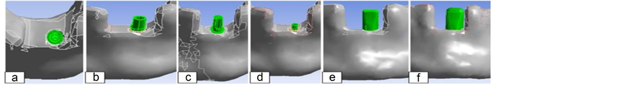
Figure 2. Location of model to mandibula.

Figure 3. Finite element models of (a) mandibula; (b) mandibula-implant complex; (c) implant; (d) straight abutment; (e) angled abutment; (f) connection element; (g) zirconia framework; (h) crown.
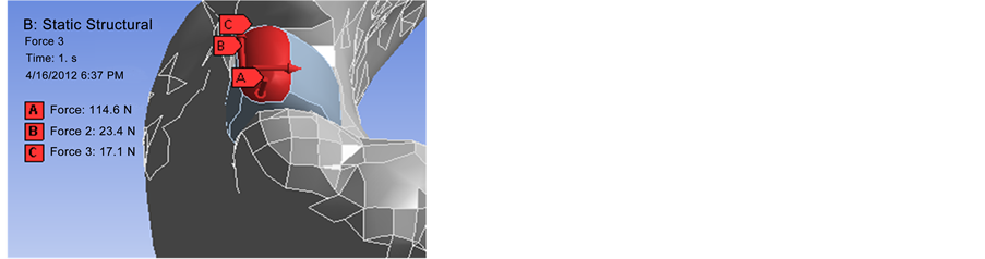
Figure 4. Masticatory forces applied to bone.
3. Results
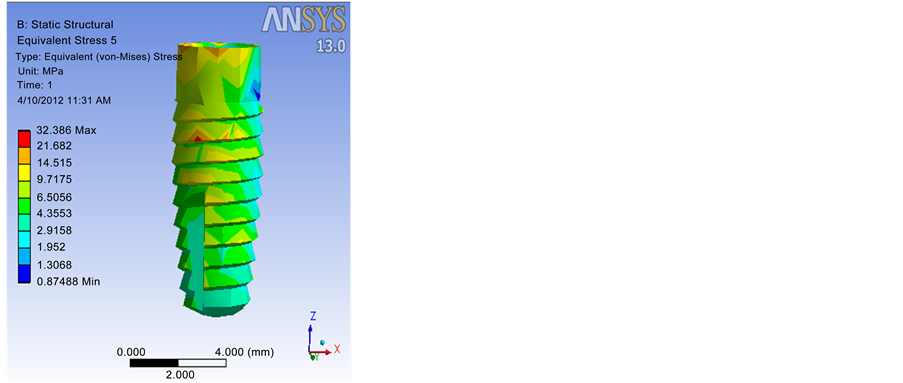
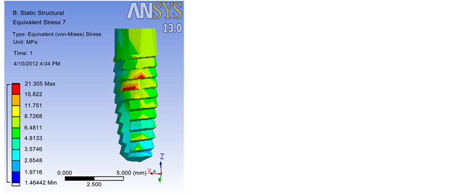
In this study, a flat implant placed in the anterior mandible in place of the missing tooth straight or angled abutments (abutment) was prepared. As a result of force on the implant, abutment, zirconium sub-structure, crown and mandible at axial, vestibule and mesiodistal direction maximum Von Misses stress values s that occurred were the findings (Table 2, Figure 5, Figure 6).
Table 2. Von Misses stress values that occurred.
 (a) Straight Abutment (b) 15˚ Angled Abutment
Figure 5. Stress distribution located at the implant for two Ti-6Al-4V models. (a) Straight abutment; (b) 15˚ angled abutment.

 (a) Straight Abutment (b) 15˚ Angled Abutment
Figure 6. Stress distribution located at the implant for two Y-TZP models. (a) Straight abutment; (b) 15˚ angled abutment.
4. Discussion
In direct proportion all models measured displacements to the stresses have increased. All fixed points of substitutions made the localization of the implant into the area where the highest value decreased in a linear fashion. This displacement shows that a fixed point, has emerged, and fixing points for the lower jaw bone and attempts to indicate strain. However, the value of displacement is very small and is not taken into account. Kayabasi et al. (2007) [14] , static, dynamic and fatigue behavior of the implant investigated. Finite element analysis, implant supported fixed partial prosthesis, bone tissue and implant-assisted composition on the fatigue behavior of the stress distributions have been chosen to examine the effect of static and dynamic loads. Small structures of the upper molar, bone, studies have used three-dimensional model. Implant and abutment for the Ti-6Al-4V alloy, cobalt chrome metal roof, porcelain occlusal feldsdspatik used for the material. Respectively lingual, axial and mesiodistal direction, N, 1.17 N, and 23.4 N, 114.6 implant is attributed three-dimensional flat and curved (75˚) in the direction imposed on the average masticatory forces. Evaluate the value of the maximum tensile loading conditions tested system of implant-abutment abutment and prosthetic screws reached the observed resistance to flow. As a result, the decision of the implant is resistant to conclude all the static and dynamic conditions.
Kohal et al. (2002) [15] , used a type of commercially pure titanium (CPTI) and partially yttrium stabilized zirconia (YPSZ) implants made from stress distribution patterns used to analyze the 3-dimensional finite ele- ment analysis method. 2 units of upper jaw implant cortical and cancellous bone surrounded by a 3-dimensional finite element analyse models of incisor made. For pure titanium metal implant supported porcelain crowns and partial-yttrium stabilized zirconia (YPSZ) to implant a ceramic crown modelled. As a result, researchers, part- yttrium stabilized zirconia implants of pure titanium implants is similar to the distribution in the upper jaw, and in particular emphasized the aesthetic could be an alternative.
In this study, the mandible was used as distinct from the work of one power plant is modelled lost tooth. 17.1 N, the average masticatory forces applied to the model, but the direction of the load affected vestibule. Ti-6Al-4V implant and Y-TZP is used as the material complex. Angled abutment 15˚ inclined abutment is used in the models used. Kayabasi et al. (2007) [14] have carried out work where both static and dynamic loading were examined in this study, only static analysis.
In our study, the Ti-6Al-4V material as well as Y-TZP was used. Different implant diameters and four different variations in implant size were created. Which material would be better in incisors were analyzed. With Tri-Matic segmentation of MIMICS mesh quality is increased. Cancellous and cortical bone of the mandible hasn’t been made. Because of cancellous bone has a very low modulus of elasticity and the result will not have much been effected. Angled abutments during placement of the implant and the correct placement are used for aesthetic appearance. In our study, the angled abutments stress results could be observed.
5. Conclusions
According to the loading conditions tested, the maximum values of the yield stress, bending and compressive resistances cannot be reached.
Low modulus of elasticity of materials with lower stress distributions was observed.
The straight abutment and 15˚ angled abutment of Y-TZP implants showed similar stress distribution to straight abutment of Ti-6Al-4V implants and 15˚ angled abutment. As a result, zirconia implants have been concluded as a viable alternative in the maxilla and mandible especially in aesthetic areas.
With this application, the design and the time that it may be possible to prevent permanent damage from the loss of the implant were determined.
Before inserting the implant into the patient complex, less cost and time were spent designed by computer and it was concluded that the desired results can be achieved.
With the limitations of this study, increased implant diameter is better than decreased implant diameter both for titanium and zirconium models but increased implant length is worse than decreased implant length with applied masticatory forces.
Acknowledgements
The authors would like to thank the Scientific Research Project by Atatürk University for funding the project by grant no: 2009/323 and Atatürk University Deparment of Mechanical Engineering and also Faculty of Dentistry.
Cite this paper
Ruhi Yeşildal,Filiz Karabudak,Funda Bayındır,Hamid Zamanlou,Melike Pınar Yıldırım,Nurdan Polat Sağsöz,Sadri Şen, (2015) Effect of Implant Diameter and Length on Stress Distribution for Titanium and Zirconia Implants by Using Finite Element Analysis (FEA). Open Access Library Journal,02,1-7. doi: 10.4236/oalib.1101211
References
- 1. Misch, C.E. (2005) Dental Implant Prosthetics.
- 2. Piconi, C. and Maccauro, G. (1999) Zirconia as Biomaterials. Biomaterials, 20, 1-25.
http://dx.doi.org/10.1016/S0142-9612(98)00010-6 - 3. Tchikawa. Y., Akagawa, Y., Nikai, H. and Tsuru, H. (1992) Tissue Compability and Stability of a New Zirconia Ceramic in Vivo. The Journal of Prosthetic Dentistry, 68, 322-326.
http://dx.doi.org/10.1016/0022-3913(92)90338-B - 4. Scarano, A., Piatelli, M., Caputi, S., Favero, G.A. and Piatelli, A. (2004) Bacterial Adhesion on Commercially Pure Titanium and Zirconium Oxide Disks. Journal of Periodontology, 75, 292-296.
http://dx.doi.org/10.1902/jop.2004.75.2.292 - 5. Geng, J., Tan, K.B.C. and Liu, G. (2001) Application of Finite Element Analysis in Implant Dentistry: A Review of the Literature. The Journal of Prosthetic Dentistry, 85, 585-598.
http://dx.doi.org/10.1067/mpr.2001.115251 - 6. Schmalz, G. (1994) Use of Cell Cultures for Toxicity Testing of Dental Materials-Advantages and Limitations. Journal of Dentistry, 22, 6-11.
http://dx.doi.org/10.1016/0300-5712(94)90032-9 - 7. Taddei, E.B. (2005) Characterization of Ti-35Nb-Zr-5Ta Alloyed Produced by Powder Metallurgy. Materials Science Forum, 498-499, 34-39.
- 8. Cooper, L.F. (1998) Biologic Determinants of Bone Formation for Osseointegration: Clues for Future Clinical Improvements. The Journal of Prosthetic Dentistry, 80, 439-449.
http://dx.doi.org/10.1016/S0022-3913(98)70009-5 - 9. Papavasiliou, G., Kamposiora, P., Bayne S.C. and Felton, D.A. (1996) Three-Dimensional Finite Element Analysis of Stress-Distribution around Single Tooth Implants as a Function of Bony Support, Prosthesis Type, and Loading during Function. The Journal of Prosthetic Dentistry, 76, 633-640.
http://dx.doi.org/10.1016/S0022-3913(96)90442-4 - 10. Dubois, G., Daas, M., Bonnet, A.S. and Lipinski, P. (2007) Biomechanical Study of a Prosthetic Solution Based on an Angled Abutment: Case of Upper Lateral Incisor. Medical Engineering Physics, 29, 989-998.
http://dx.doi.org/10.1016/j.medengphy.2006.10.017 - 11. ASTM C848 (2011) Standard Test Method for Young’s Modulus, Shear Modulus, and Poisson’s Ratio for Ceramic Whitewares by Resonance. 88.
- 12. ASTM F417 (1996) Test Method for Flexural Strength (Modulus of Rupture) of Electronic-Grade Ceramics (With-drawn 2001). 78.
- 13. Pelosi, G. (2007) The Finite-Element Method, Part I: R. L. Courant: Historical Corner.
- 14. Kayabasi, O., Yuzbasioglu, E. and Erzincanli, F. (2006) Static, Dynamic and Fatigue Behaviors of Dental Implant Using Finite Element Method. Advances in Engineering Software, 37, 649-658.
http://dx.doi.org/10.1016/j.advengsoft.2006.02.004 - 15. Kohal, R.J., Papavasiliou, G., Kamposiora, P., Tripodakis, A. and Strub, J.R. (2002) Three-Dimensional Computerized Stress Analysis of Commercially Pure Titanium and Yttrium-Partially Stabilized Zirconia Implants. The International Journal of Prosthodontics, 15, 189-194.
NOTES

*Corresponding author.