Intelligent Control and Automation, 2011, 2, 233-240
doi:10.4236/ica.2011.23028 Published Online August 2011 (http://www.SciRP.org/journal/ica)
Copyright © 2011 SciRes. ICA
Fuzzy PID Controllers Using FPGA Technique for Real
Time DC Motor Speed Control
Basil Hamed, Moayed Al-Mobaied
Electrical Engineering Department, Islamic University of Gaza, Gaza, Palestine
E-mail: bhamed@iugaza.edu
Received April 3, 2011; revised June 10, 2011; accepted June 17, 2011
Abstract
The design of intelligent control systems has become an area of intense research interest. The development
of an effective methodology for the design of such control systems undoubtedly requires the synthesis of
many concepts from artificial intelligence. The most commonly used controller in the industry field is the
proportional-plus-integral-plus-derivative (PID) controller. Fuzzy logic controller (FLC) provides an alterna-
tive to PID controller, especially when the available system models are inexact or unavailable. Also rapid
advances in digital technologies have given designers the option of implementing controllers using Field
Programmable Gate Array (FPGA) which depends on parallel programming. This method has many advan-
tages over classical microprocessors. In this research, A model of the fuzzy PID control system is imple-
mented in real time with a Xilinx FPGA (Spartan-3A, Xilinx Company, 2007). It is introduced to maintain a
constant speed to when the load varies. The model of a DC motor is considered as a second order system
with load variation as an example for complex model systems. For comparison purpose, two widely used
controllers “PID and Fuzzy” have been implemented in the same FPGA card to examine the performance of
the proposed system. These controllers have been tested using Matlab/Simulink program under speed and
load variation conditions. The controllers were implemented to run the motor as real time application under
speed and load variation conditions and showed the superiority of Fuzzy-PID.
Keywords: DC Motor, Fuzzy Logic Control, PID Controller, Real Time, FPGA
1. Introduction
Due to its excellent speed control characteristics DC
motor has been widely used in industry even though its
maintenance costs are higher than the induction motor,
the speed of DC motor can be adjusted to a great extent
so as to provide easy control and high performance [1,2].
At present, Proportional-Integral-Derivative “PID” con-
troller, due to its simplicity, stability, and robustness, is a
type of controller that is most widely applied [2,3].
However, it is difficult to design when the accurate
model of plant is complicated or the environment of the
load on the plant is variable. For Dc motors, factors such
as unknown load characteristic and parameter variation
influence seriously the controlling effect of speed con-
troller. Fuzzy control does not strictly need any mathe-
matical model of the plant. It is based on plant operator
experience, and it is very easy to apply. Fuzzy Logic has
been successfully applied to a large number of control
applications. The most commonly used controller is the
proportional-plus-integral-plus-derivative controller, which
requires a mathematical model of the system. Fuzzy
logic controller provides an alternative to PID controller
since it is a good tool for the control of systems that are
difficult in modeling. The control action in fuzzy logic
controllers can be expressed with simple “if-then” rules.
Fuzzy control gives robust performance for a linear or
nonlinear plant with parameter variation. Hardware im-
plementation of the controller can be achieved in a num-
ber of ways to create new products [4]. The most popular
method of implementing Fuzzy controller is using a gen-
eral-purpose microprocessor or microcontroller. The
simple and usual way to implement these systems is to
realize it as a software program on general purpose
computers, these ways cannot be considered as a suitable
design solution [5]. Higher density programmable logic
device such as Field Programmable Gate Arrays (FPGAs)
can be used to integrate large amounts of logic in a single
B. HAMED ET AL.
234
IC. FPGAs are one of the fastest growing parts of the
digital integrated circuit market in recent times [6].
Rapid advances in digital technologies have given de-
signers the option of implementing a controller on a va-
riety of Programmable Logic Device (PLD), Field Pro-
grammable Gate Array (FPGA), etc. [6]. FPGA is suit-
able for fast implementation controller and can be pro-
grammed to do any type of digital functions. Applications
of FPGAs include industrial motor drivers, real time
systems, digital signal processing, computer hardware
emulation and a growing range of other areas. The novel
approach, which is proposed in this research, is: Design
and practical implementation of a real time Fuzzy-PID
controller using modern FPGA card (Spartan-3A, Xilinx
Company, 2007) for speed control of DC motor with
load variation as an application. This paper is organized
into six sections. Section 2 handles basic principles of
our DC motor. Section 3 focuses on Fuzzy logic sets.
Section 4 deals with FPGA and VHDL software imple-
mentation. Section 5 presents the design of the three
types of controllers; also, the simulation and results are
included. The last section concludes the design and the
implementation of the system.
2. DC Motor
DC motor shown in Figure 1 is the one of most common
motors which used in industrial motion control systems.
Figure 2 display the electric circuit of the armature
and the free body diagram of the rotor in DC motor. Ta-
ble 1 contains the motor parameters used in this paper.
Figure 1. DC motor.
Figure 2. Schematic representation of the considered DC
motor.
Table 1. Dc motor parameters.
Parameter Value
Moment of inertia of the rotor J = 0.00025 Nm/rad/s2
Damping (friction) of the mechanical
system b = 0.0001 Nm/rad/s
Terminal resistance RA = 0.5
Terminal inductance LA = 1.5 mH
Electromotive force constant K = 0.05 Nm / A
The input is the armature voltage V in Volts, and the
measured variables are the angular velocity of the shaft w
in radians per second. The motor torque, T, is related to
the armature current, i, by a constant factor K:
TKi (1)
The back electromotive force (emf) Vb, is related to
the angular velocity by:
d
K K
d
b
Vt
 (2)
From Figure 2 we can write the following equations
based on the Newton’s law combined with the
Kirchhoff’s law:
2
2
dd
d
d
θθ
J
b K i
t
t (3)
d
dd
iθ
LRi V- K
tt
 d
(4)
Using the Laplace transform, equations (3) and (4) can
be written as:

2
Js θs bsθ
s
KI s (5)
 
LsIsRIsV s-Ksθ
s
 (6)
From (6) we can express I(s):


Vs Ksθ
s
Is RLs
(7)
And substitute it in (5) to obtain:
  
2Vs Ksθ
s
JS θsbsθsK RLs
 (8)
This equation for the DC motor is shown in the block
diagram at Figure 3.
From the block diagram in Figure 3, it is easy to see
that the transfer function from the input voltage, V(s), to
the angular velocity.

 
2
a
sK
Gs Vs
RLsJsb K


(9)
Copyright © 2011 SciRes. ICA
B. M. HAMED ET AL.235
T(s)
Figure 3. A block diagram of the DC motor.
 
 
2
v
ωsK
Gs VsRLsJs bK


(10)
3. Fuzzy Logic
Fuzzy Logic (FL) is an approach to control engineering
problems, which mimics how a person would make deci-
sions, only much faster. FL incorporates a simple
rule-based “ IF X AND Y THEN Z “approach to a solv-
ing control problem rather than attempting to model a
system mathematically [7,8]. The FL model is empiri-
cally-based, relying on an operator’s experience rather
than his technical understanding of the system. In other
words fuzzy logic is used in system control and analysis
design, because it shortens the time for engineering de-
velopment and sometimes, in the case of highly complex
systems, is the only way to solve the problem [9,10].
Every Fuzzy system is composed of four principal blocks
as shown in Figure 4:
1) Knowledge base: Rules and parameters for mem-
bership functions.
2) Decision making unit: Inference operations on the
rules.
3) Fuzzification interface: Transformation of the crisp
inputs into degrees of match with linguistic variables.
4) Defuzzification interface: Transformation of the
Fuzzy result of the inference into a crisp output.
4. Field Programmable Gate Arrays
(FPGAs)
FPGAs shown in Figure 5, stands for Field Programma-
ble Gate Arrays are one type of programmable logic de-
vices (PLDs). It is based on an integrated circuit that can
be configured by the user in order to implement digital
logic functions of varying complexities. FPGAs can be
very effectively used for control purposes in processes
demanding very high loop cycle time. One of the funda-
mental advantage of FPGA over DSP or other micro-
processors is the freedom of programming parallelism
[11,12]. Since different parts of FPGA can be configured
to perform independent functions simultaneously, its
performance is just not tied to clock rate as in DSPs. This
F
UZZY
Figure 4. General structure of fuzzy inference system.
Figure 5. Structure of a Xilinx FPGA standard.
fact enables FPGA’s to score over general purpose com-
puting chips in the digital control systems implementa-
tion [13].
5. Controllers Design
This paper presents the process used to design three
kinds of widely used controllers (PID, Fuzzy, and
Fuzzy-PID) for the DC motor using FPGA technique.
Figure 6 contains the main block diagram for the sys-
tem.
To provide DC motor with the required voltage, we
need a PWM driver shown in Figure 7. PWM is a way
of digitally encoding analog signal levels. The duty cycle
of a square wave is modulated to encode a specific
analog signal level. The PWM signal is still digital
Figure 6. Block diagram for DC motor controller.
Copyright © 2011 SciRes. ICA
B. HAMED ET AL.
236
Figure 7. PWM signals.
because, at any given instant of time, the full DC supply
is either fully on or fully off. The voltage or current
source is supplied to the analog load by means of a
repeating series of on and off pulses. Figure 7 shows
three different PWM signals with PWM output at a 10%,
50%, and 90% duty cycles, respectively. These three
PWM outputs encode three different analog signal values,
at 10%, 50%, and 90% of the full strength of the Dc
voltage [13].
Three different controllers were developed in this pa-
per: PID controller, Fuzzy controller, and Fuzzy-PID
controller. Finally, a comparison will be made among
these controllers to find the best performer.
5.1. PID Controller
The block diagram of a PID controller algorithm is
shown in Figure 8.
It’s required to build a digital PID controller in the
FPGA card. There are many approaches are available to
convert from analogue to digital. In this proper we used
the Tus- tin approach. The equation which represents the
PID controller is:
 
d
dd
pi d
et
utKetK ettKt
 
(10)
There are many methods available to get the best val-
ues of Kp, Ki, and Kd. One approach is to use a technique
that was developed in the 1950’s but has stood the time
and is still used today. This is known as the Ziegler
Nichols tuning method [14].
A general rule of thumb in control design is to sample
at least 4 to 20 times the rise time of the system response,
so the sampling time will be chosen to 4.1 milliseconds.
Hence, the output of the PID controller will feed to the
plant speed register of the PWM.
The Simulink block diagram for the PID speed con-
troller for DC motor is shown in Figure 9. The controller
has been tested using Simulink in Matlab. The result of
PID controller is shown in Figure 10.
Figure 8. PID algorithm.
Figure 9. PID speed controller for Dc motor.
Figure 10. PID controller step response.
Copyright © 2011 SciRes. ICA
B. M. HAMED ET AL.237
5.2. Fuzzy Logic Controller “FLC”
FLC has been constructed Using VHDL and embedded
PicoBalze processor in FPGA. The block diagram for the
FLC for the DC motor is shown in Figure 11.
FLC has two inputs, which are: Error (E) and the Error
change (CE), and one output feeding to the plant speed
register of the PWM. Figure 12 illustrates the method
used in reaching the desired speed value. For example, at
stage A the Error is positive (desired speed –actual speed)
and the Change Error (Error - last Error) is negative,
which mean that the response is heading in the right di-
rection; hence, the FLC will go forward in this direction.
Using the same criteria at stage B, the Error is negative
and CE is big negative; hence, the response is heading in
wrong direction so FLC will change its direction to enter
Stage C, until reaching the desired speed.
In this paper, Mamdani approach in FPGA has been
used to implement FLC for the DC motor. FLC contains
three basic parts: Fuzzification, Base rule, and Defuzzi-
fication.
5.2.1. Fuzzifi cation
The Fuzzy set of the Error input which contains 7 Tri-
angular memberships is shown in Figure 13.
Figure 14 illustrates the Fuzzy set of the Change Error
input which contains 7 Triangular memberships.
Figure 15 illustrates the Fuzzy set of the output which
contains 7 Triangular memberships.
5.2.2. Cont rol B ase Rul e s
Table 2 presents the knowledge base defining the rules
for the desired relationship between the input and output
Figure 11. FLC speed controller for Dc motor.
Figure 12. Error and error change approach in FLC.
Figure 13. Error fuzzy set of FLC.
Figure 14. Change error fuzzy set of FLC.
Figure 15. Fuzzy set of FLC output entering to plant speed
register.
Table 2. Fuzzy controller base rules
E
CE NB NM NS ZE PS PM PB
NB NB NB NB NB NM NS ZE
NM NB NB NM NM NS ZE PS
NZ NB NM NS NS ZE PS PM
ZE NB NM NS ZE PS PM PB
PS NM NS ZE PS PS PM PB
PM NS ZE PS PM PM PB PB
PB ZE PS PM PB PB PB PB
variables in terms of the membership functions. The
control rules are represented as a set of:
IF Error is.. and Change Error isTHEN the output
will.
Figure 16 shows the surface of the base rules used in
FLC.
Copyright © 2011 SciRes. ICA
B. HAMED ET AL.
238
5.2.3. Defuzzification
The center of gravity “centroid” method was used in this
paper. Figure 17 shows the Simulink block diagram for
the Fuzzy speed controller for DC motor. The controller
has been tested using Simulink in Matlab. The result of
Fuzzy controller is shown in Figure 18.
5.3. Fuzzy-PID Controller
Here, another approach which depends on mixing the
PID controller with Fuzzy controller in FPGA using
VHDL code. Hence, the value of the PID parameters will
be evaluated using the Fuzzy controller. A complete de-
sign of the system is shown in Figure 19. The Fuzzy sets
Figure 16. Rules surface of FLC
Figure 17. Fuzzy logic speed controller.
Figure 18. Fuzzy controller step response.
for the output: Kp, Ki, and Kd is shown in Figure 20,
practically there are three different Fuzzy sets for these
parameters. The inputs of the controller used are the er-
ror and change of error as presented in the previous sec-
tion.
Table 3 presents the base rules of Fuzzy-PID control-
ler (Kp). Practically there are three base rules tables for
Kp, Ki, and Kd
Simulink block diagram for the Fuzzy-PID speed con-
troller for DC motor is shown in Figure 21.
Figure 19. Fuzzy-P ID contr oller for the induction motor.
Figure 20. Fuzzy sets for Kp, Ki, and Kd with different
memberships boundaries.
Table 3. Base rules for fuzzy-PID controller (Kp).
E
CE NB NM NS ZE PS PM PB
PB ZE PS PM PB PB PB PB
PM NS ZE PS PM PB PB PB
PS NM NS ZE PS PM PB PB
ZE NB NM NS ZE PS PM PB
NS NB NB NM NS ZE PS PM
NM NB NB NB NM NS ZE PS
NB NB NB NB NB NM NS ZE
Copyright © 2011 SciRes. ICA
B. M. HAMED ET AL.239
Figure 21. Fuzzy-PID logic speed controller.
The controller has been tested using Simulink in Mat-
lab. The result of Fuzzy-PID controller is shown in Fig-
ure 22.
5.4. Results Comparison
Table 4 shows controller’s comparison, hence it’s found
that the Fuzzy-PID controller is the best controller
among the other controllers.
All three controllers presented in this paper are im-
plemented in hardware using the FPGA card; then these
controllers have been tested with real time experiments.
An auxiliary program in the FPGA is implemented to test
the step response of these controllers. Then our program
displays the results on the LCD using the PicoBlaze proc-
essor technique as a real time tester. The LCD displays
Figure 22. Fuzzy-PID controller step response.
Table 4. Controllers comparison.
Controller Overshoot Settling time Steady state error
PID 4.82 0.0187 0
Fuzzy 2.43 0.014 0
Fuzzy-PID 0.965 0.00344 0
the desired speed, the overshoot, the settling time, and
the PID parameters for each controller as shown in Fig-
ures 23 and 24. The result of the real time experiment
we have is very close to the Matlab simulation. A digital
optical encoder with two channels is used to read the
speed of the motor, and it displays the direction of the
motor as shown in Figure 25. Many features were ap-
plied to the system as overload protection, motor direc-
tion switch and also we used three switches to enter the
controllers’ type and to specify the parameters of the PID
controller.
5.5. Modelsim Results
PWM algorithm was tested using Modelsim (VHDL
simulator) program, which is a powerful simulator estab-
lished by Xilinx Company. Using this simulator we can
specify the input and the output ports then the simulator
will test the VHDL code which shown in Figure 26.
6. Conclusions
In this paper, Fuzzy-PID controller has been selected to
Figure 23. FPGA card with LCD and controlling keys.
Figure 24. Real time experiments results on the LCD.
Copyright © 2011 SciRes. ICA
B. HAMED ET AL.
Copyright © 2011 SciRes. ICA
240
7. References control the speed of DC motor due to its advantages over
the traditional PID controller. The control scheme was
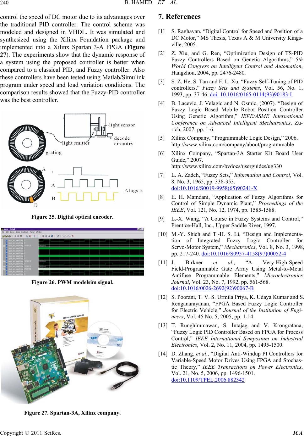
modeled and designed in VHDL. It was simulated and
synthesized using the Xilinx Foundation package and
implemented into a Xilinx Spartan 3-A FPGA (Figure
27). The experiments show that the dynamic response of
a system using the proposed controller is better when
compared to a classical PID, and Fuzzy controller. Also
these controllers have been tested using Matlab/Simulink
program under speed and load variation conditions. The
comparison results showed that the Fuzzy-PID controller
was the best controller.
[1] S. Raghavan, “Digital Control for Speed and Position of a
DC Motor,” MS Thesis, Texas A & M University Kings-
ville, 2005.
[2] Z. Xiu, and G. Ren, “Optimization Design of TS-PID
Fuzzy Controllers Based on Genetic Algorithms,” 5th
World Congress on Intelligent Control and Automation,
Hangzhou, 2004, pp. 2476-2480.
[3] S. Z. He, S. Tan and F. L. Xu, “Fuzzy Self-Tuning of PID
controllers,” Fuzzy Sets and Systems, Vol. 56, No. 1,
1993, pp. 37-46. doi: 10.1016/0165-0114(93)90183-I
[4] B. Lacevic, J. Velagic and N. Osmic, (2007). “Design of
Fuzzy Logic Based Mobile Robot Position Controller
Using Genetic Algorithm,” IEEE/ASME International
Conference on Advanced Intelligent Mechatronics, Zu-
rich, 2007, pp. 1-6.
[5] Xilinx Company, “Programmable Logic Design,” 2006.
http://www.xilinx.com/company/about/programmable
[6] Xilinx Company, “Spartan-3A Starter Kit Board User
Guide,” 2007.
http://www.xilinx.com/bvdocs/userguides/ug330
[7] L. A. Zadeh, “Fuzzy Sets,” Information and Control, Vol.
8, No. 3, 1965, pp. 338-353.
doi:10.1016/S0019-9958(65)90241-X
[8] E. H. Mamdani, “Application of Fuzzy Algorithms for
Control of Simple Dynamic Plant,” Proceedings of the
IEEE, Vol. 121, No. 12, 1974, pp. 1585-1588.
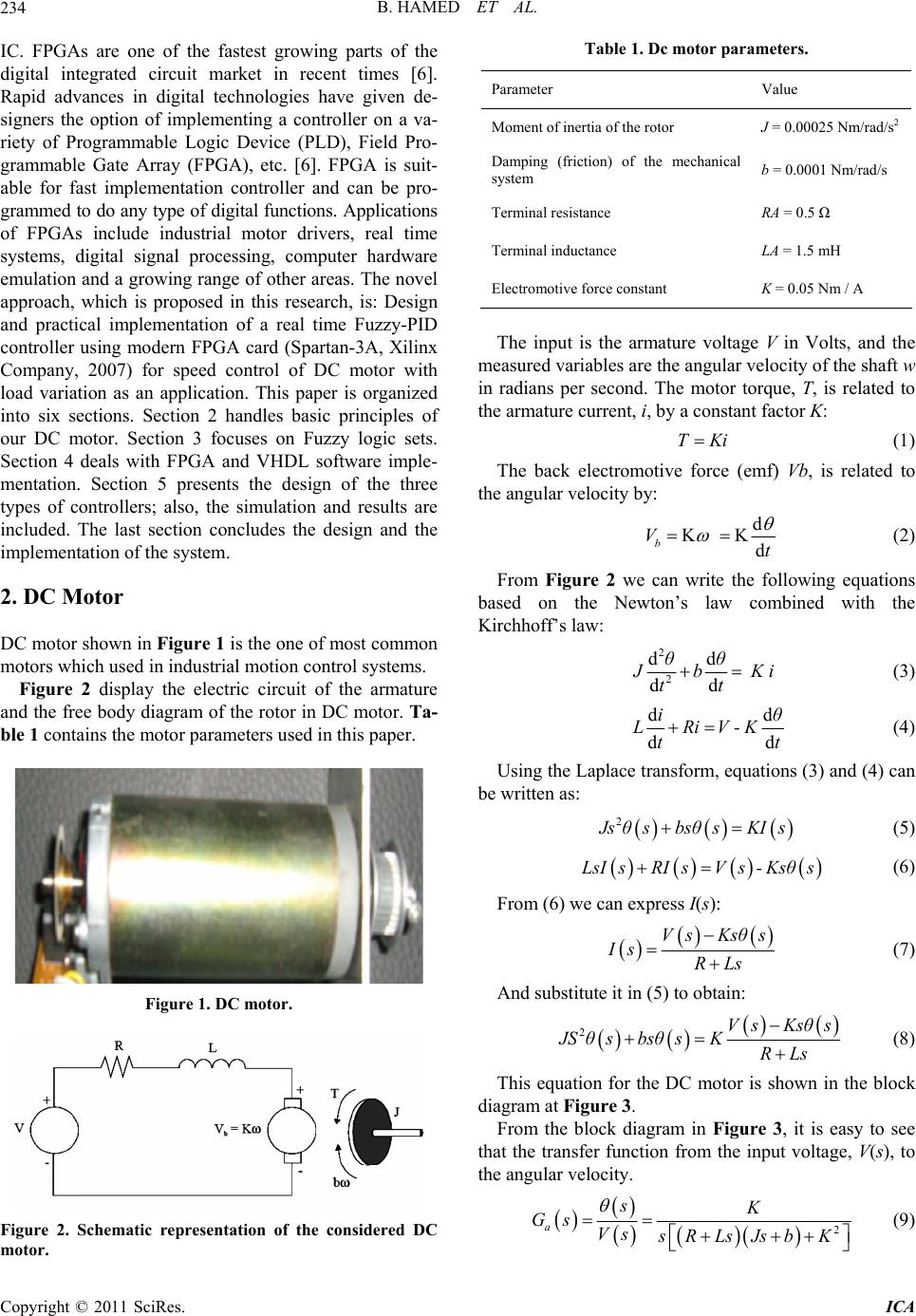
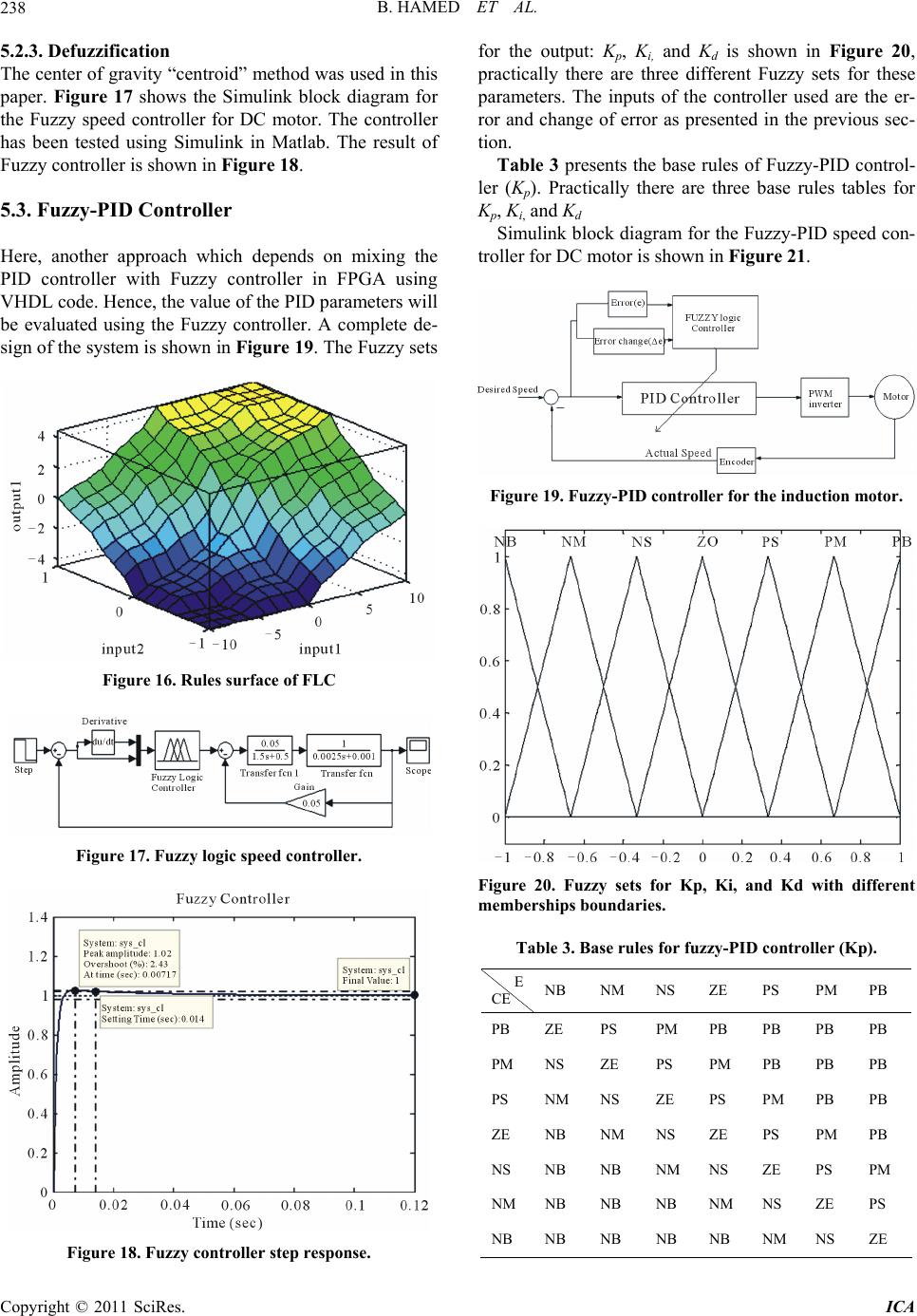
Figure 25. Digital optical encoder. [9] L.-X. Wang, “A Course in Fuzzy Systems and Control,”
Prentice-Hall, Inc., Upper Saddle River, 1997.
[10] M.-Y. Shieh and T.-H. S. Li, “Design and Implementa-
tion of Integrated Fuzzy Logic Controller for
Servo-Motor System,” Mechatronics, Vol. 8, No. 3, 1998,
pp. 217-240. doi:10.1016/S0957-4158(97)00052-4
, 1992, pp. 561-568.
[11] J. Birkner et al., “A Very-High-Speed
Field-Programmable Gate Array Using Metal-to-Metal
Antifuse Programmable Elements,” Microelectronics
Journal, Vol. 23, No. 7
doi:10.1016/0026-2692(92)90067-B
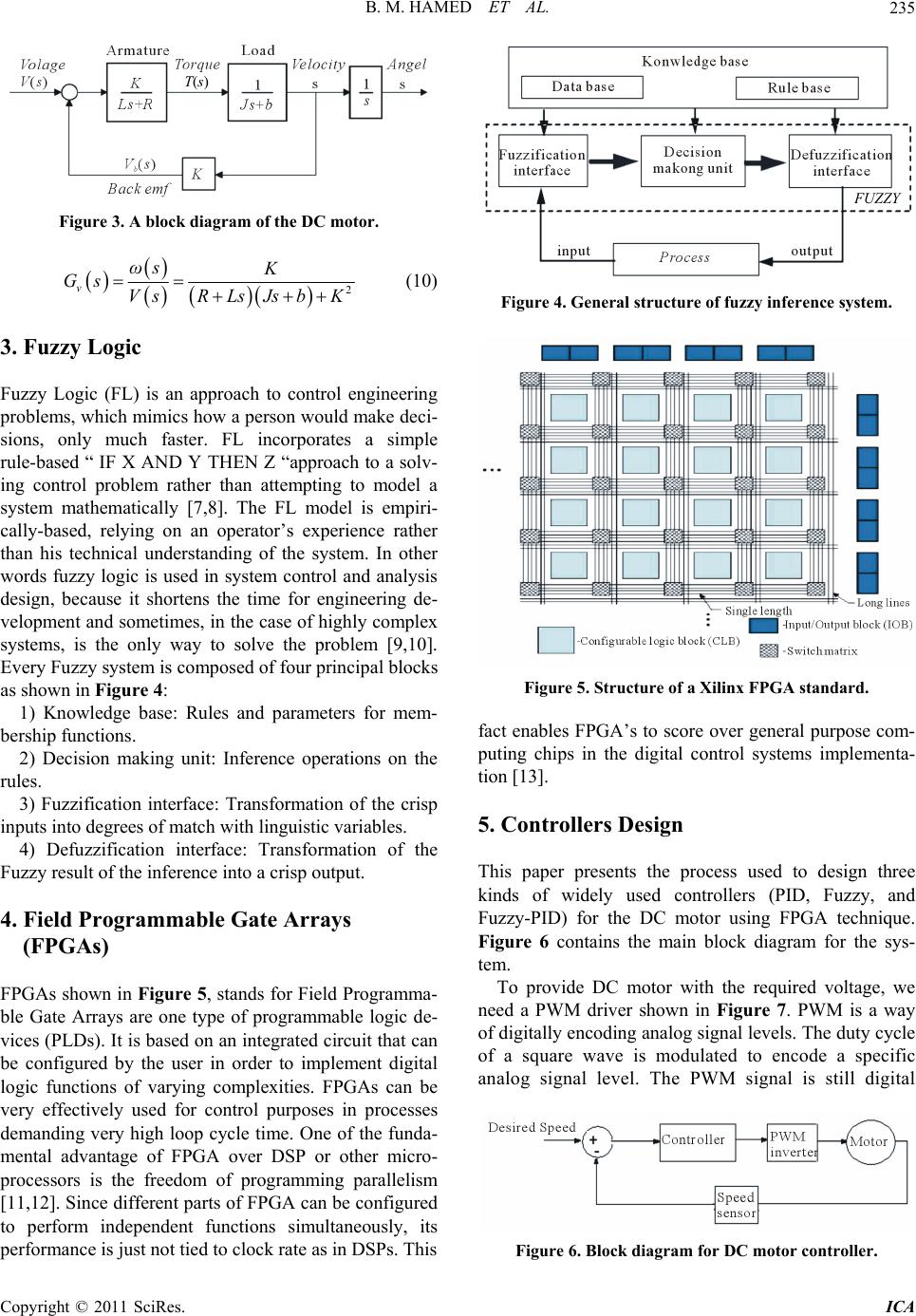
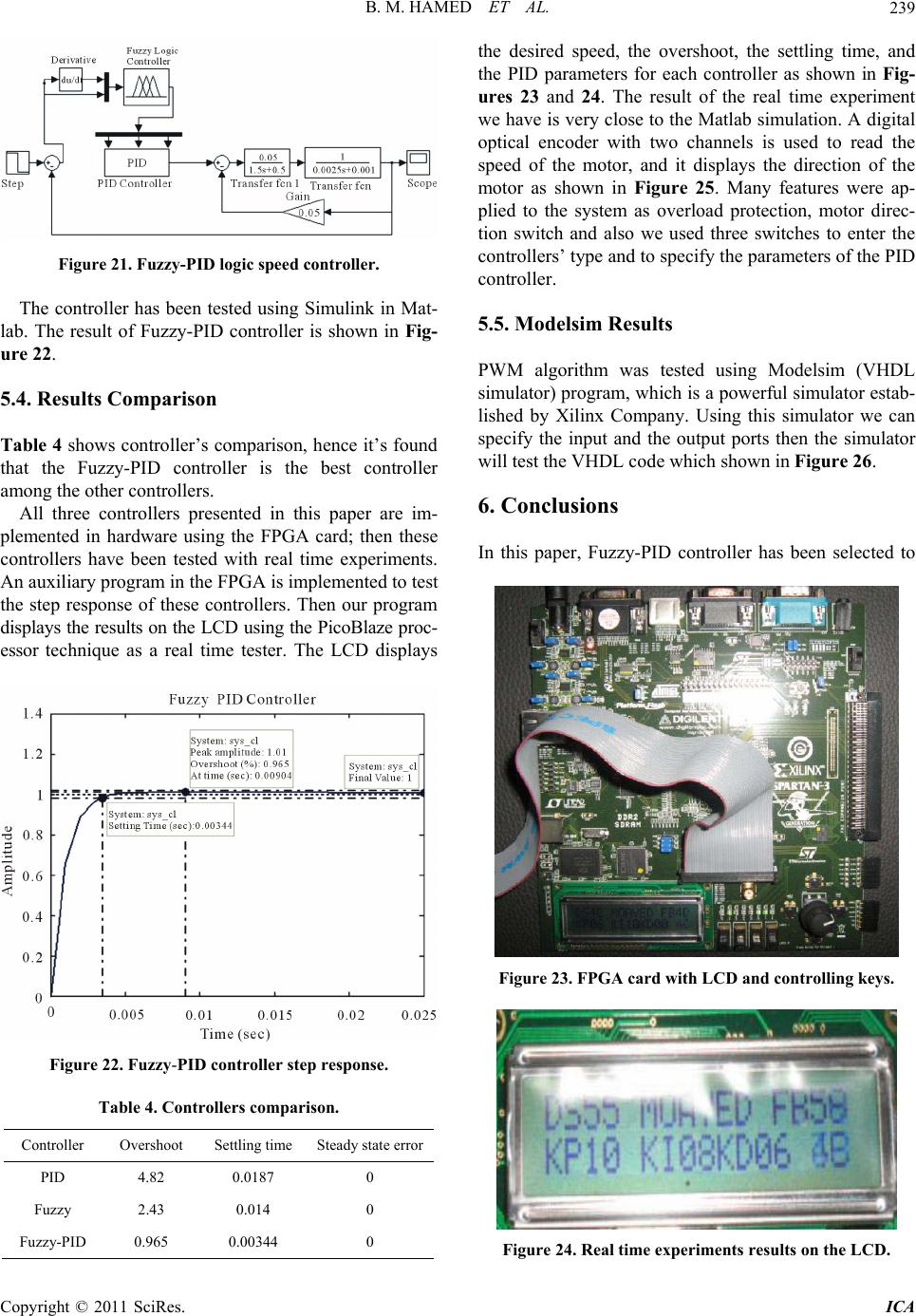
Figure 26. PWM modelsim signal.
[12] S. Poorani, T. V. S. Urmila Priya, K. Udaya Kumar and S.
Renganarayanan, “FPGA Based Fuzzy Logic Controller
for Electric Vehicle,” Journal of the Institution of Engi-
neers, Vol. 45 No. 5, 2005, pp. 1-14.
[13] T. Runghimmawan, S. Intajag and V. Krongratana,
“Fuzzy Logic PID Controller Based on FPGA for Process
Control,” IEEE International Symposium on Industrial
Electronics, Vol. 2, No. 11, 2004, pp. 1495-1500.
[14] D. Zhang, et al., “Digital Anti-Windup PI Controllers for
Variable-Speed Motor Drives Using FPGA and Stochas-
tic Theory,” IEEE Transactions on Power Electronics,
Vol. 21, No. 5, 2006, pp. 1496-1501.
doi:10.1109/TPEL.2006.882342
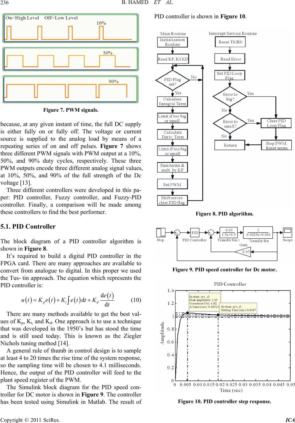
Figure 27. Spartan-3A, Xilinx company.