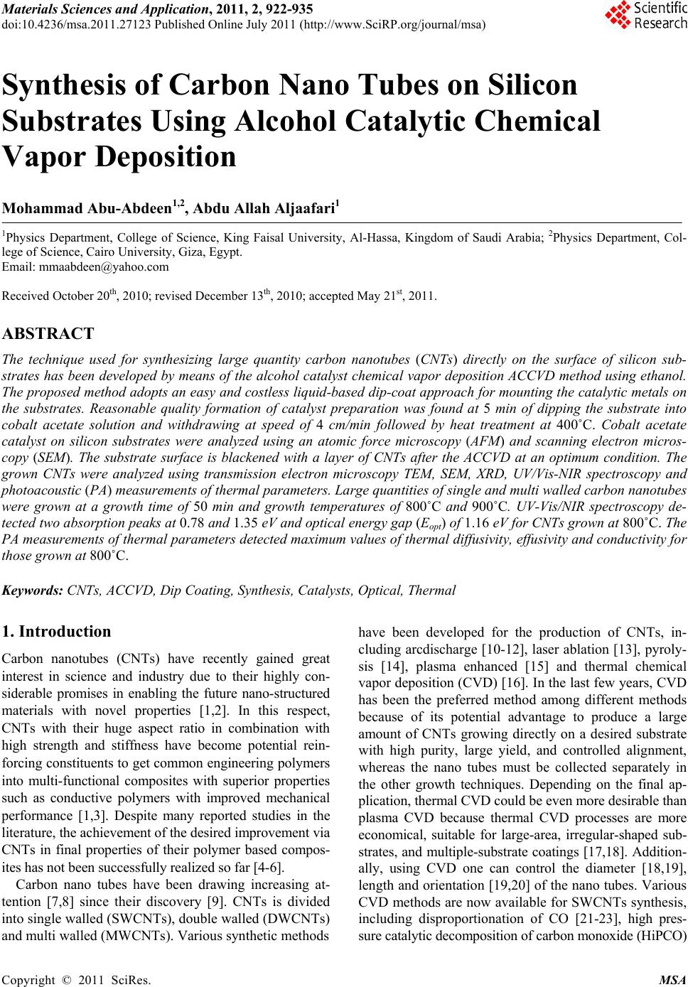
 Materials Sciences and Applicatio n, 2011, 2, 922-935 doi:10.4236/msa.2011.27123 Published Online July 2011 (http://www.SciRP.org/journal/msa) Copyright © 2011 SciRes. MSA Synthesis of Carbon Nano Tubes on Silicon Substrates Using Alcohol Catalytic Chemical Vapor Deposition Mohammad Abu-Abdeen1,2, Abdu Allah Aljaafari1 1Physics Department, College of Science, King Faisal University, Al-Hassa, Kingdom of Saudi Arabia; 2Physics Department, Col- lege of Science, Cairo University, Giza, Egypt. Email: mmaabdeen@yahoo.com Received October 20th, 2010; revised December 13th, 2010; accepted May 21st, 2011. ABSTRACT The technique used for synthesizing large quantity carbon nanotubes (CNTs) directly on the surface of silicon sub- strates has been developed by means of the alcohol catalyst chemical vapor deposition ACCVD method using ethanol. The proposed method adopts an easy and costless liquid-based dip-coat approach for mounting the catalytic metals on the substrates. Reasonable quality formation of catalyst preparation was found at 5 min of dipping the substrate into cobalt acetate solution and withdrawing at speed of 4 cm/min followed by heat treatment at 400˚C. Cobalt acetate catalyst on silicon substrates were analyzed using an atomic force microscopy (AFM) and scanning electron micros- copy (SEM). The substrate surface is blackened with a layer of CNTs after the ACCVD at an optimum condition. The grown CNTs were analyzed using transmission electron microscopy TEM, SEM, XRD, UV/Vis-NIR spectroscopy and photoacoustic (PA) measurements of thermal parameters. Large quantities of single and multi walled carbon nanotubes were grown at a growth time of 50 min and growth temperatures of 800˚C and 900˚C. UV-Vis/NIR spectroscopy de- tected two absorption peaks at 0.78 and 1.35 eV and optical energy gap (Eopt) of 1.16 eV for CNTs grown at 800˚C. The PA measurements of thermal parameters detected maximum values of thermal diffusivity, effusivity and conductivity for those grown at 800˚C. Keywords: CNTs, ACCVD, Dip Coating, Synthesis, Catalysts, Optical, Thermal 1. Introduction Carbon nanotubes (CNTs) have recently gained great interest in science and industry due to their highly con- siderable promises in enabling the future nano-structured materials with novel properties [1,2]. In this respect, CNTs with their huge aspect ratio in combination with high strength and stiffness have become potential rein- forcing constituents to get common engineering polymers into multi-functional composites with superior properties such as conductive polymers with improved mechanical performance [1,3]. Despite many reported studies in the literature, the achievement of the desired improvement via CNTs in final properties of their polymer based compos- ites has not been successfully realized so far [4-6]. Carbon nano tubes have been drawing increasing at- tention [7,8] since their discovery [9]. CNTs is divided into single walled (SWCNTs), double walled (DWCNTs) and multi walled (MWCNTs). Various synthetic methods have been developed for the production of CNTs, in- cluding arcdischarge [10-12], laser ablation [13], pyroly- sis [14], plasma enhanced [15] and thermal chemical vapor deposition (CVD) [16]. In the last few years, CVD has been the preferred method among different methods because of its potential advantage to produce a large amount of CNTs growing directly on a desired substrate with high purity, large yield, and controlled alignment, whereas the nano tubes must be collected separately in the other growth techniques. Depending on the final ap- plication, thermal CVD could be even more desirable than plasma CVD because thermal CVD processes are more economical, suitable for large-area, irregular-shaped sub- strates, and multiple-substrate coatings [17,18]. Addition- ally, using CVD one can control the diameter [18,19], length and orientation [19,20] of the nano tubes. Various CVD methods are now available for SWCNTs synthesis, including disproportionation of CO [21-23], high pres- sure catalytic decomposition of carbon monoxide (HiPCO) 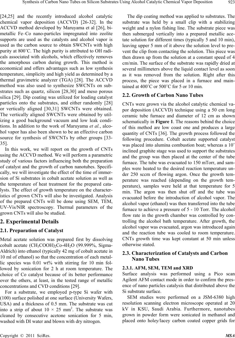 Synthesis of Carbon Nano Tubes on Silicon Substrates Using Alcohol Catalytic Chemical Vapor Deposition923 [24,25] and the recently introduced alcohol catalytic chemical vapor deposition (ACCVD) [26-32]. In the ACCVD method developed by Maruyama et al [26], bi- metallic Fe–Co nano-particles impregnated into zeolite supports are used as the catalysts and alcohol vapor is used as the carbon source to obtain SWCNTs with high purity at 800˚C. The high purity is attributed to OH radi- cals associated with alcohols, which effectively removes the amorphous carbon during growth. This method is economical and offers advantages such as low synthesis temperature, simplicity and high yield as determined by a thermal gravimetric analyzer (TGA) [28]. The ACCVD method was also used to synthesize SWCNTs on sub- strates such as quartz, silicon [28,30] and meso porous silica [29]. Dip coating was utilized for loading catalyst particles onto the substrates, and either randomly [28] or vertically aligned [30,31] SWCNTs were obtained. The vertically aligned SWCNTs were obtained by util- izing a good background vacuum and low leak condi- tions. In addition to the work of Maruyama et al., alco- hol vapor has also been shown to be an effective carbon source for synthesis of SWCNTs by other groups [33- 35]. In this work, we will report on the growth of CNTs using the ACCVD method. We will perform a parametric study of various factors influencing both the preparation of catalyst and the growth of carbon nanotubes. Specifi- cally, we will investigate the effect of the time of immer- sion of Si substrates in cobalt acetate solution as well as the temperature of heat treatment for the prepared cata- lysts. The effect of growth temperature on the character- istics of grown CNTs will also be investigated. Analysis of the prepared CNTs will be done using SEM, TEM, UV-Vis/NIR spectroscopy. Thermal parameters of the grown CNTs will also be studied. 2. Experimental Details 2.1. Preparation of Catalyst Metal acetate solution was prepared first by dissolving cobalt acetate (CH3COOH)2Co-4H2O (99.999%, Sigma- Aldrich) into ethanol (typically 42 mg of cobalt acetate in 10 ml of ethanol) so that the concentration of each metal- lic species was 0.01 wt% with stirring for 10 min fol- lowed by sonication for 2 h at room temperature. The choice of Co catalyst because of its better performance over the others, at least, in the tested range of metallic concentrations and CVD conditions [29]. For a substrate, we employed p-type Si wafer with (100) surface polished at one surface (University Wafers, USA) and a thickness of 0.5 mm. The substrate was cut into a strip of about 10 × 25 mm2. The substrate was cleaned by consecutive acetone sonication for 5 min, washed with DI water and blown with dry nitrogen. The dip coating method was applied to substrates. The substrate was held by a small clip with a stabilizing weight and a nylon fishing line. The substrate piece was then submerged vertically into a prepared metallic ace- tate solution for different times (typically 5 and 10 min), leaving upper 5 mm of it above the solution level to pre- vent the clip from contacting the solution. This piece was then drawn up from the solution at a constant speed of 4 cm/min. The surface of the substrate was rapidly dried at several millimeters above the liquid contact level as soon as it was removed from the solution. Right after this process, the piece was placed in a furnace and main- tained at 400˚C or 500˚C for 5 or 10 min. 2.2. Growth of Carbon Nano Tubes CNTs were grown via the alcohol catalytic chemical va- por deposition (ACCVD) technique using a 50 cm long ceramic tube furnace and diameter of 12 cm as shown schematically in Figure 1. The reasons behind the choice of this method are low coast one and produces a large quantity of CNTs [36]. The growth process followed the following procedure. Cobalt acetate supported catalyst was placed into alumina combustion boat; whereas a 10˚ inclined graphite stage was used to support the substrates and the group was then placed at the center of the tube furnace. The tube was evacuated to 150 mTorr, and sam- ples were heated to the desired reaction temperature un- der 250 sccm of flowing argon. Once the growth tem- perature was reached (depending on the growth tem- perature), samples were held at that temperature for 5 min. The argon was then shut off and the tube was evacuated before the introduction of alcohol vapor. The alcohol vapor (ethanol) was then transferred into the tube furnace to achieve a pressure of 5 - 10 Torr. The alcohol flow rate in the growth chamber was controlled by con- trolling the alcohol bath temperature. After growth, the alcohol vapor was evacuated, argon was introduced again and the reaction tube was cooled to room temperature. CNTs growth time was kept constant at 50 min unless otherwise stated. 2.3. Characterization of Catalysts and Carbon Nano Tubes 2.3.1. AFM, SEM, TEM and XRD Surface analysis was performed using a Pico scan Agilent AFM contact mode in order to confirm the pres- ence of nano particles catalysis that distributed above the Si substrate surface. SEM studies were performed on a JSM-6380 high resolution scanning electron microscope operated at 20 kV in KSU, Saudi Arabia. Furthermore, nanotubes grown in powder form were sonicated in methanol and placed onto holey/lacey carbon coated copper grids for Copyright © 2011 SciRes. MSA 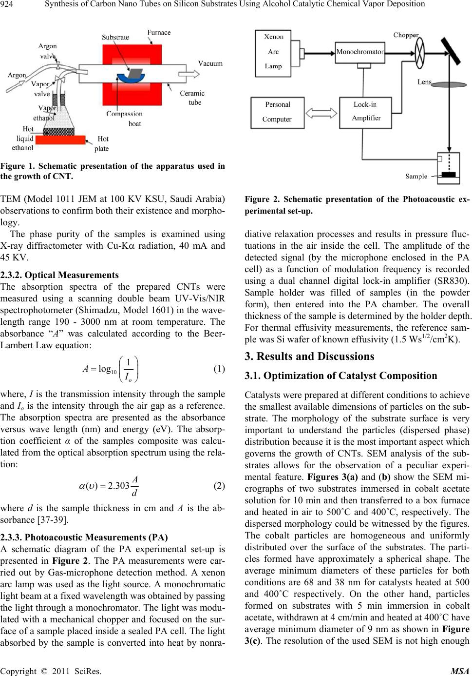 Synthesis of Carbon Nano Tubes on Silicon Substrates Using Alcohol Catalytic Chemical Vapor Deposition 924 Figure 1. Schematic presentation of the apparatus used in the growth of CNT. TEM (Model 1011 JEM at 100 KV KSU, Saudi Arabia) observations to confirm both their existence and morpho- logy. The phase purity of the samples is examined using X-ray diffractometer with Cu-K radiation, 40 mA and 45 KV. 2.3.2. Optical Measurements The absorption spectra of the prepared CNTs were measured using a scanning double beam UV-Vis/NIR spectrophotometer (Shimadzu, Model 1601) in the wave- length range 190 - 3000 nm at room temperature. The absorbance “A” was calculated according to the Beer- Lambert Law equation: 10 1 log o A (1) where, I is the transmission intensity through the sample and Io is the intensity through the air gap as a reference. The absorption spectra are presented as the absorbance versus wave length (nm) and energy (eV). The absorp- tion coefficient α of the samples composite was calcu- lated from the optical absorption spectrum using the rela- tion: ( )2.303 d (2) where d is the sample thickness in cm and A is the ab- sorbance [37-39]. 2.3.3. Photoacoustic Measurements (PA) A schematic diagram of the PA experimental set-up is presented in Figure 2. The PA measurements were car- ried out by Gas-microphone detection method. A xenon arc lamp was used as the light source. A monochromatic light beam at a fixed wavelength was obtained by passing the light through a monochromator. The light was modu- lated with a mechanical chopper and focused on the sur- face of a sample placed inside a sealed PA cell. The light absorbed by the sample is converted into heat by nonra- Figure 2. Schematic presentation of the Photoacoustic ex- perimental set-up. diative relaxation processes and results in pressure fluc- tuations in the air inside the cell. The amplitude of the detected signal (by the microphone enclosed in the PA cell) as a function of modulation frequency is recorded using a dual channel digital lock-in amplifier (SR830). Sample holder was filled of samples (in the powder form), then entered into the PA chamber. The overall thickness of the sample is determined by the holder depth. For thermal effusivity measurements, the reference sam- ple was Si wafer of known effusivity (1.5 Ws1/2/cm2K). 3. Results and Discussions 3.1. Optimization of Catalyst Composition Catalysts were prepared at different conditions to achieve the smallest available dimensions of particles on the sub- strate. The morphology of the substrate surface is very important to understand the particles (dispersed phase) distribution because it is the most important aspect which governs the growth of CNTs. SEM analysis of the sub- strates allows for the observation of a peculiar experi- mental feature. Figures 3(a) and (b) show the SEM mi- crographs of two substrates immersed in cobalt acetate solution for 10 min and then transferred to a box furnace and heated in air to 500˚C and 400˚C, respectively. The dispersed morphology could be witnessed by the figures. The cobalt particles are homogeneous and uniformly distributed over the surface of the substrates. The parti- cles formed have approximately a spherical shape. The average minimum diameters of these particles for both conditions are 68 and 38 nm for catalysts heated at 500 and 400˚C respectively. On the other hand, particles formed on substrates with 5 min immersion in cobalt acetate, withdrawn at 4 cm/min and heated at 400˚C have average minimum diameter of 9 nm as shown in Figure 3(c). The resolution of the used SEM is not high enough Copyright © 2011 SciRes. MSA 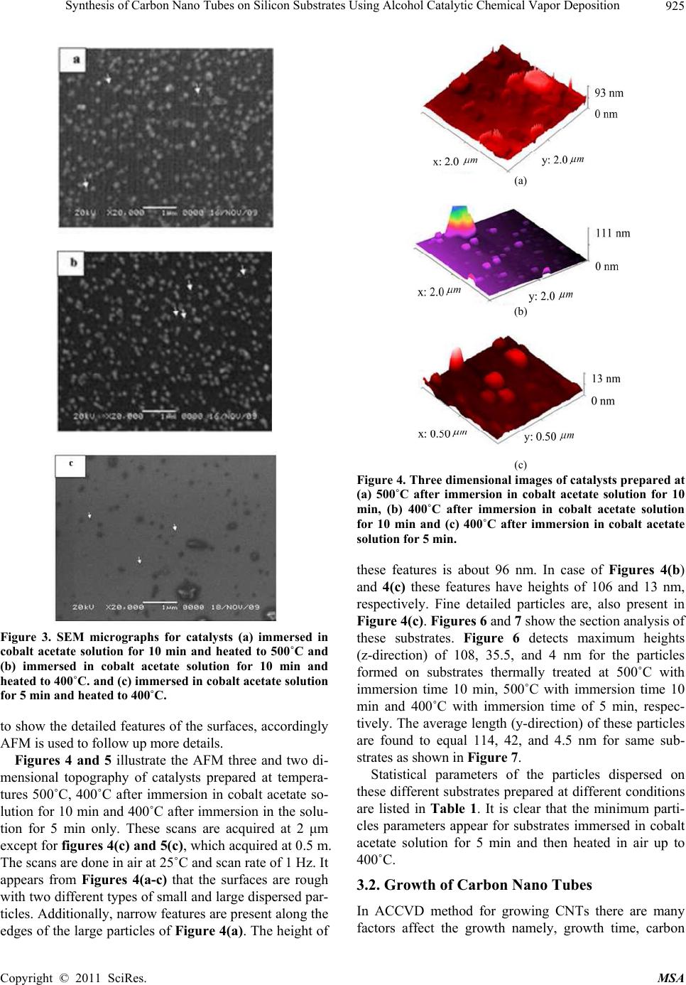 Synthesis of Carbon Nano Tubes on Silicon Substrates Using Alcohol Catalytic Chemical Vapor Deposition Copyright © 2011 SciRes. MSA 925 (a) (b) (c) Figure 4. Three dimensional images of catalysts prepared at (a) 500˚C after immersion in cobalt acetate solution for 10 min, (b) 400˚C after immersion in cobalt acetate solution for 10 min and (c) 400˚C after immersion in cobalt acetate solution for 5 min. these features is about 96 nm. In case of Figures 4(b) and 4(c) these features have heights of 106 and 13 nm, respectively. Fine detailed particles are, also present in Figure 4(c). Figures 6 and 7 show the section analysis of these substrates. Figure 6 detects maximum heights (z-direction) of 108, 35.5, and 4 nm for the particles formed on substrates thermally treated at 500˚C with immersion time 10 min, 500˚C with immersion time 10 min and 400˚C with immersion time of 5 min, respec- tively. The average length (y-direction) of these particles are found to equal 114, 42, and 4.5 nm for same sub- strates as shown in Figure 7. Figure 3. SEM micrographs for catalysts (a) immersed in cobalt acetate solution for 10 min and heated to 500˚C and (b) immersed in cobalt acetate solution for 10 min and heated to 400˚C. and (c) immersed in cobalt acetate solution for 5 min and heated to 400˚C. to show the detailed features of the surfaces, accordingly AFM is used to follow up more details. Figures 4 and 5 illustrate the AFM three and two di- mensional topography of catalysts prepared at tempera- tures 500˚C, 400˚C after immersion in cobalt acetate so- lution for 10 min and 400˚C after immersion in the solu- tion for 5 min only. These scans are acquired at 2 μm except for figures 4(c) and 5(c), which acquired at 0.5 m. The scans are done in air at 25˚C and scan rate of 1 Hz. It appears from Figures 4(a-c) that the surfaces are rough with two different types of small and large dispersed par- ticles. Additionally, narrow features are present along the edges of the large particles of Figure 4(a). The height of Statistical parameters of the particles dispersed on these different substrates prepared at different conditions are listed in Table 1. It is clear that the minimum parti- cles parameters appear for substrates immersed in cobalt acetate solution for 5 min and then heated in air up to 400˚C. 3.2. Growth of Carbon Nano Tubes In ACCVD method for growing CNTs there are many factors affect the growth namely, growth time, carbon 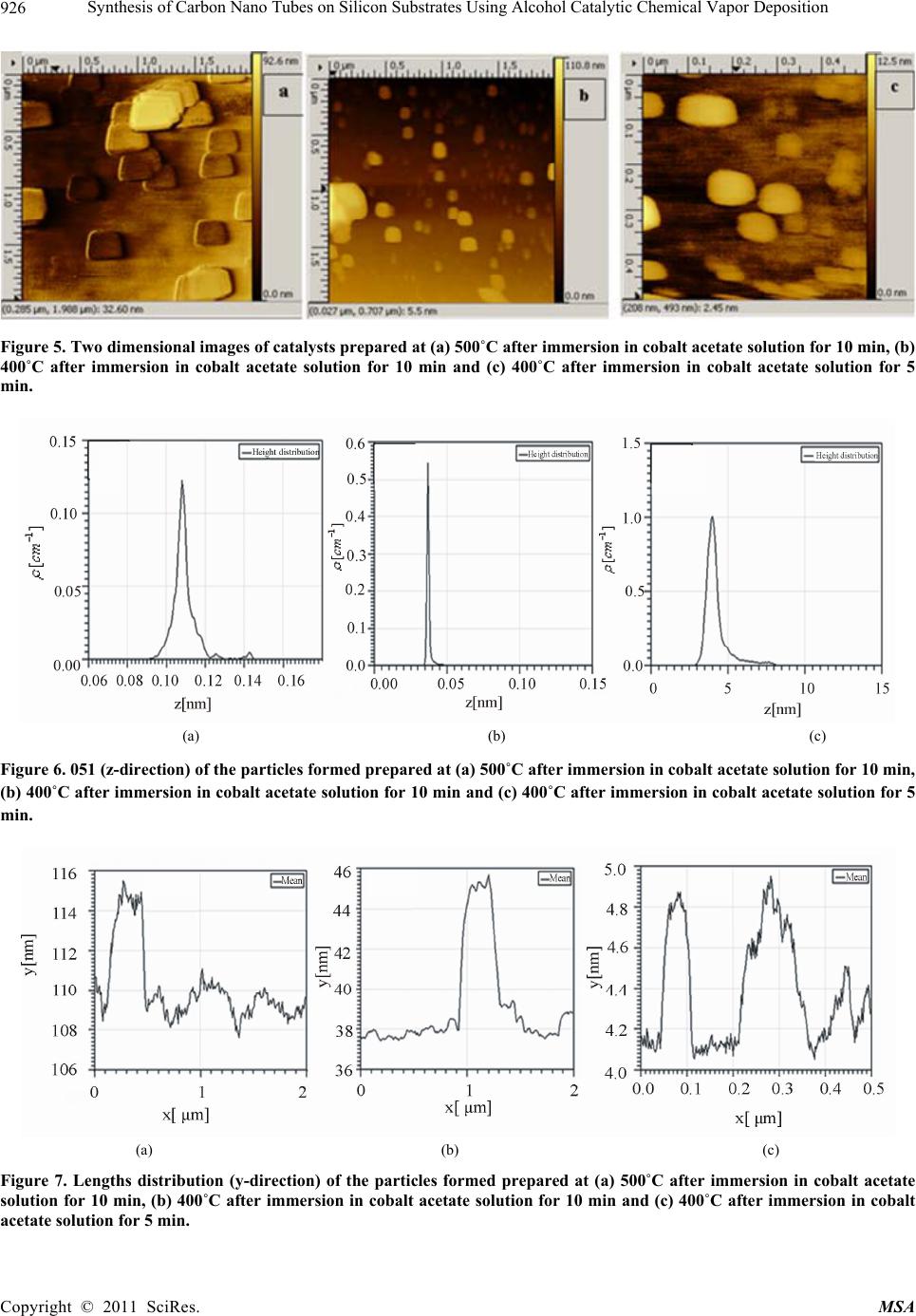 Synthesis of Carbon Nano Tubes on Silicon Substrates Using Alcohol Catalytic Chemical Vapor Deposition 926 Figure 5. Two dimensional images of catalysts prepared at (a) 500˚C after immersion in cobalt acetate solution for 10 min, (b) 400˚C after immersion in cobalt acetate solution for 10 min and (c) 400˚C after immersion in cobalt acetate solution for 5 min. (a) (b) (c) Figure 6. 051 (z-direction) of the particles formed prepared at (a) 500˚C after immersion in cobalt acetate solution for 10 min, (b) 400˚C after immersion in cobalt acetate solution for 10 min and (c) 400˚C after immersion in cobalt acetate solution for 5 min. (a) (b) (c) Figure 7. Lengths distribution (y-direction) of the particles formed prepared at (a) 500˚C after immersion in cobalt acetate solution for 10 min, (b) 400˚C after immersion in cobalt acetate solution for 10 min and (c) 400˚C after immersion in cobalt acetate solution for 5 min. Copyright © 2011 SciRes. MSA 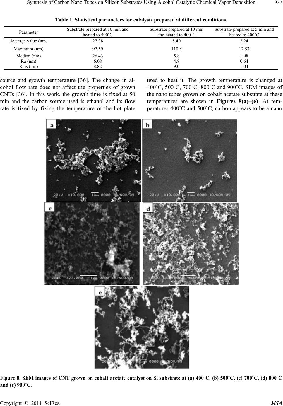 Synthesis of Carbon Nano Tubes on Silicon Substrates Using Alcohol Catalytic Chemical Vapor Deposition Copyright © 2011 SciRes. MSA 927 Table 1. Statistical parameters for catalysts prepared at different conditions. Parameter Substrate prepared at 10 min and heated to 500˚C Substrate prepared at 10 min and heated to 400˚C Substrate prepared at 5 min and heated to 400˚C Average value (nm) 27.38 8.40 2.24 Maximum (nm) 92.59 110.8 12.53 Median (nm) 26.43 5.8 1.98 Ra (nm) 6.08 4.8 0.64 Rms (nm) 8.82 9.0 1.04 source and growth temperature [36]. The change in al- cohol flow rate does not affect the properties of grown CNTs [36]. In this work, the growth time is fixed at 50 min and the carbon source used is ethanol and its flow rate is fixed by fixing the temperature of the hot plate used to heat it. The growth temperature is changed at 400˚C, 500˚C, 700˚C, 800˚C and 900˚C. SEM images of the nano tubes grown on cobalt acetate substrate at these temperatures are shown in Figures 8(a)–(e). At tem- peratures 400˚C and 500˚C, carbon appears to be a nano Figure 8. SEM images of CNT grown on cobalt acetate catalyst on Si substrate at (a) 400˚C, (b) 500˚C, (c) 700˚C, (d) 800˚C and (e) 900˚C. 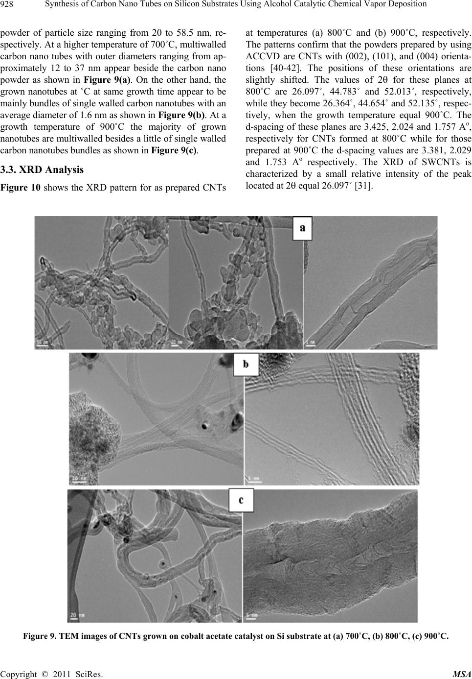 Synthesis of Carbon Nano Tubes on Silicon Substrates Using Alcohol Catalytic Chemical Vapor Deposition 928 powder of particle size ranging from 20 to 58.5 nm, re- spectively. At a higher temperature of 700˚C, multiwalled carbon nano tubes with outer diameters ranging from ap- proximately 12 to 37 nm appear beside the carbon nano powder as shown in Figure 9(a). On the other hand, the grown nanotubes at ˚C at same growth time appear to be mainly bundles of single walled carbon nanotubes with an average diameter of 1.6 nm as shown in Figure 9(b). At a growth temperature of 900˚C the majority of grown nanotubes are multiwalled besides a little of single walled carbon nanotubes bundles as shown in Figure 9(c). 3.3. XRD Analysis Figure 10 shows the XRD pattern for as prepared CNTs at temperatures (a) 800˚C and (b) 900˚C, respectively. The patterns confirm that the powders prepared by using ACCVD are CNTs with (002), (101), and (004) orienta- tions [40-42]. The positions of these orientations are slightly shifted. The values of 2 for these planes at 800˚C are 26.097˚, 44.783˚ and 52.013˚, respectively, while they become 26.364˚, 44.654˚ and 52.135˚, respec- tively, when the growth temperature equal 900˚C. The d-spacing of these planes are 3.425, 2.024 and 1.757 Ao, respectively for CNTs formed at 800˚C while for those prepared at 900˚C the d-spacing values are 3.381, 2.029 and 1.753 Ao respectively. The XRD of SWCNTs is characterized by a small relative intensity of the peak located at 2 equal 26.097˚ [31]. Figure 9. TEM images of CNTs grown on cobalt acetate catalyst on Si substrate at (a) 700˚C, (b) 800˚C, (c) 900˚C. Copyright © 2011 SciRes. MSA 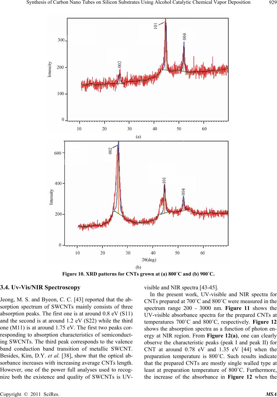 Synthesis of Carbon Nano Tubes on Silicon Substrates Using Alcohol Catalytic Chemical Vapor Deposition929 (a) (b) Figure 10. XRD patterns for CNTs grown at (a) 800˚C and (b) 900˚C. 3.4. Uv-Vis/NIR Spectroscopy Jeong, M. S. and Byeon, C. C. [43] reported that the ab- sorption spectrum of SWCNTs mainly consists of three absorption peaks. The first one is at around 0.8 eV (S11) and the second is at around 1.2 eV (S22) while the third one (M11) is at around 1.75 eV. The first two peaks cor- responding to absorption characteristics of semiconduct- ing SWCNTs. The third peak corresponds to the valence band conduction band transition of metallic SWCNT. Besides, Kim, D.Y. et al. [38], show that the optical ab- sorbance increases with increasing average CNTs length. However, one of the power full analyses used to recog- nize both the existence and quality of SWCNTs is UV- visible and NIR spectra [43-45]. In the present work, UV-visible and NIR spectra for CNTs prepared at 700˚C and 800˚C were measured in the spectrum range 200 - 3000 nm. Figure 11 shows the UV-visible absorbance spectra for the prepared CNTs at temperatures 700˚C and 800˚C, respectively. Figure 12 shows the absorption spectra as a function of photon en- ergy at NIR region. From Figure 12(a), one can clearly observe the characteristic peaks (peak I and peak II) for CNT at around 0.78 eV and 1.35 eV [44] when the preparation temperature is 800˚C. Such results indicate that the prepared CNTs are mostly single walled type at least at preparation temperature of 800˚C. Furthermore, the increase of the absorbance in Figure 12 when the Copyright © 2011 SciRes. MSA 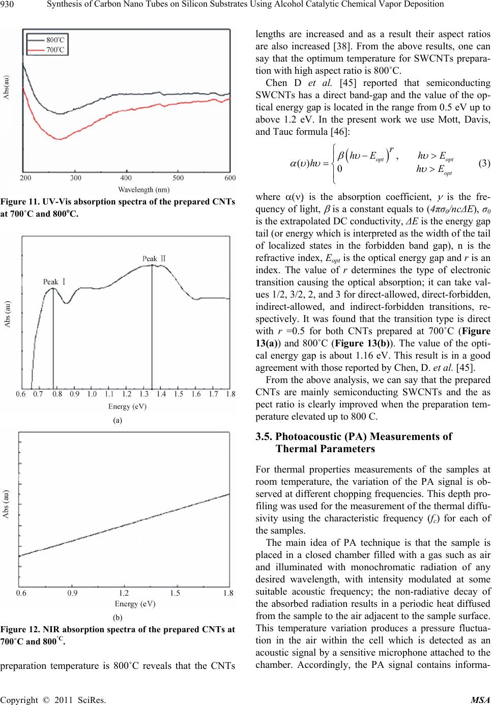 Synthesis of Carbon Nano Tubes on Silicon Substrates Using Alcohol Catalytic Chemical Vapor Deposition 930 Figure 11. UV-Vis absorption spectra of the prepared CNTs at 700˚C and 800oC. (a) (b) Figure 12. NIR absorption spectra of the prepared CNTs at 700˚C and 800˚C. preparation temperature is 800˚C reveals that the CNTs lengths are increased and as a result their aspect ratios are also increased [38]. From the above results, one can say that the optimum temperature for SWCNTs prepara- tion with high aspect ratio is 800˚C. Chen D et al. [45] reported that semiconducting SWCNTs has a direct band-gap and the value of the op- tical energy gap is located in the range from 0.5 eV up to above 1.2 eV. In the present work we use Mott, Davis, and Tauc formula [46]: , () 0 opt opt opt r hEh E hhE (3) where is the absorption coefficient, is the fre- quency of light, is a constant equals to (4πσ0/ncΔE), σ0 is the extrapolated DC conductivity, ΔE is the energy gap tail (or energy which is interpreted as the width of the tail of localized states in the forbidden band gap), n is the refractive index, Eopt is the optical energy gap and r is an index. The value of r determines the type of electronic transition causing the optical absorption; it can take val- ues 1/2, 3/2, 2, and 3 for direct-allowed, direct-forbidden, indirect-allowed, and indirect-forbidden transitions, re- spectively. It was found that the transition type is direct with r =0.5 for both CNTs prepared at 700˚C (Figure 13(a)) and 800˚C (Figure 13(b)). The value of the opti- cal energy gap is about 1.16 eV. This result is in a good agreement with those reported by Chen, D. et al. [45]. From the above analysis, we can say that the prepared CNTs are mainly semiconducting SWCNTs and the as pect ratio is clearly improved when the preparation tem- perature elevated up to 800 C. 3.5. Photoacoustic (PA) Measurements of Thermal Parameters For thermal properties measurements of the samples at room temperature, the variation of the PA signal is ob- served at different chopping frequencies. This depth pro- filing was used for the measurement of the thermal diffu- sivity using the characteristic frequency (fc) for each of the samples. The main idea of PA technique is that the sample is placed in a closed chamber filled with a gas such as air and illuminated with monochromatic radiation of any desired wavelength, with intensity modulated at some suitable acoustic frequency; the non-radiative decay of the absorbed radiation results in a periodic heat diffused from the sample to the air adjacent to the sample surface. This temperature variation produces a pressure fluctua- tion in the air within the cell which is detected as an acoustic signal by a sensitive microphone attached to the chamber. Accordingly, the PA signal contains informa- Copyright © 2011 SciRes. MSA 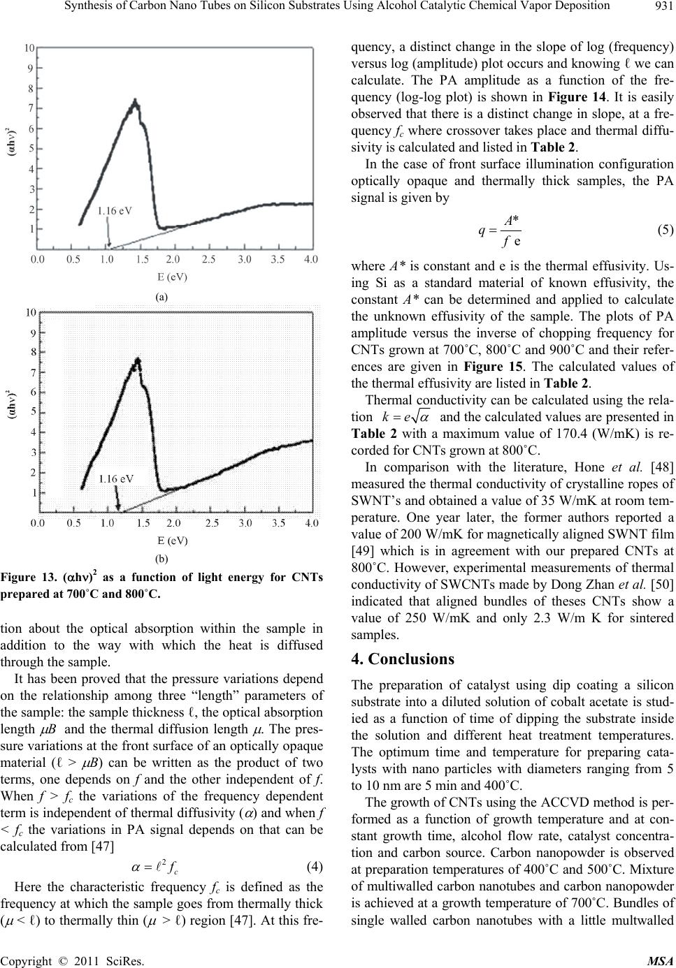 Synthesis of Carbon Nano Tubes on Silicon Substrates Using Alcohol Catalytic Chemical Vapor Deposition931 (a) (b) Figure 13. (h)2 as a function of light energy for CNTs prepared at 700˚C and 800˚C. tion about the optical absorption within the sample in addition to the way with which the heat is diffused through the sample. It has been proved that the pressure variations depend on the relationship among three “length” parameters of the sample: the sample thickness ℓ, the optical absorption length B and the thermal diffusion length . The pres- sure variations at the front surface of an optically opaque material (ℓ > B) can be written as the product of two terms, one depends on f and the other independent of f. When f > fc the variations of the frequency dependent term is independent of thermal diffusivity ( ) and when f < fc the variations in PA signal depends on that can be calculated from [47] 2 c (4) Here the characteristic frequency fc is defined as the frequency at which the sample goes from thermally thick ( < ℓ) to thermally thin ( > ℓ) region [47]. At this fre- quency, a distinct change in the slope of log (frequency) versus log (amplitude) plot occurs and knowing ℓ we can calculate. The PA amplitude as a function of the fre- quency (log-log plot) is shown in Figure 14. It is easily observed that there is a distinct change in slope, at a fre- quency fc where crossover takes place and thermal diffu- sivity is calculated and listed in Table 2. In the case of front surface illumination configuration optically opaque and thermally thick samples, the PA signal is given by * e q (5) where A* is constant and e is the thermal effusivity. Us- ing Si as a standard material of known effusivity, the constant A* can be determined and applied to calculate the unknown effusivity of the sample. The plots of PA amplitude versus the inverse of chopping frequency for CNTs grown at 700˚C, 800˚C and 900˚C and their refer- ences are given in Figure 15. The calculated values of the thermal effusivity are listed in Table 2. Thermal conductivity can be calculated using the rela- tion ke and the calculated values are presented in Table 2 with a maximum value of 170.4 (W/mK) is re- corded for CNTs grown at 800˚C. In comparison with the literature, Hone et al. [48] measured the thermal conductivity of crystalline ropes of SWNT’s and obtained a value of 35 W/mK at room tem- perature. One year later, the former authors reported a value of 200 W/mK for magnetically aligned SWNT film [49] which is in agreement with our prepared CNTs at 800˚C. However, experimental measurements of thermal conductivity of SWCNTs made by Dong Zhan et al. [50] indicated that aligned bundles of theses CNTs show a value of 250 W/mK and only 2.3 W/m K for sintered samples. 4. Conclusions The preparation of catalyst using dip coating a silicon substrate into a diluted solution of cobalt acetate is stud- ied as a function of time of dipping the substrate inside the solution and different heat treatment temperatures. The optimum time and temperature for preparing cata- lysts with nano particles with diameters ranging from 5 to 10 nm are 5 min and 400˚C. The growth of CNTs using the ACCVD method is per- formed as a function of growth temperature and at con- stant growth time, alcohol flow rate, catalyst concentra- tion and carbon source. Carbon nanopowder is observed at preparation temperatures of 400˚C and 500˚C. Mixture of multiwalled carbon nanotubes and carbon nanopowder is achieved at a growth temperature of 700˚C. Bundles of single walled carbon nanotubes with a little multwalled Copyright © 2011 SciRes. MSA 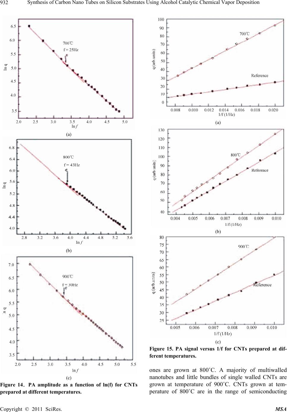 Synthesis of Carbon Nano Tubes on Silicon Substrates Using Alcohol Catalytic Chemical Vapor Deposition Copyright © 2011 SciRes. MSA 932 (a) (a) (b) (b) (c) Figure 15. PA signal versus 1/f for CNTs prepared at dif- ferent temperatures. ones are grown at 800˚C. A majority of multiwalled nanotubes and little bundles of single walled CNTs are grown at temperature of 900˚C. CNTs grown at tem- perature of 800˚C are in the range of semiconducting (c) Figure 14.PA amplitude as a function of ln(f) for CNTs prepared at different temperatures. 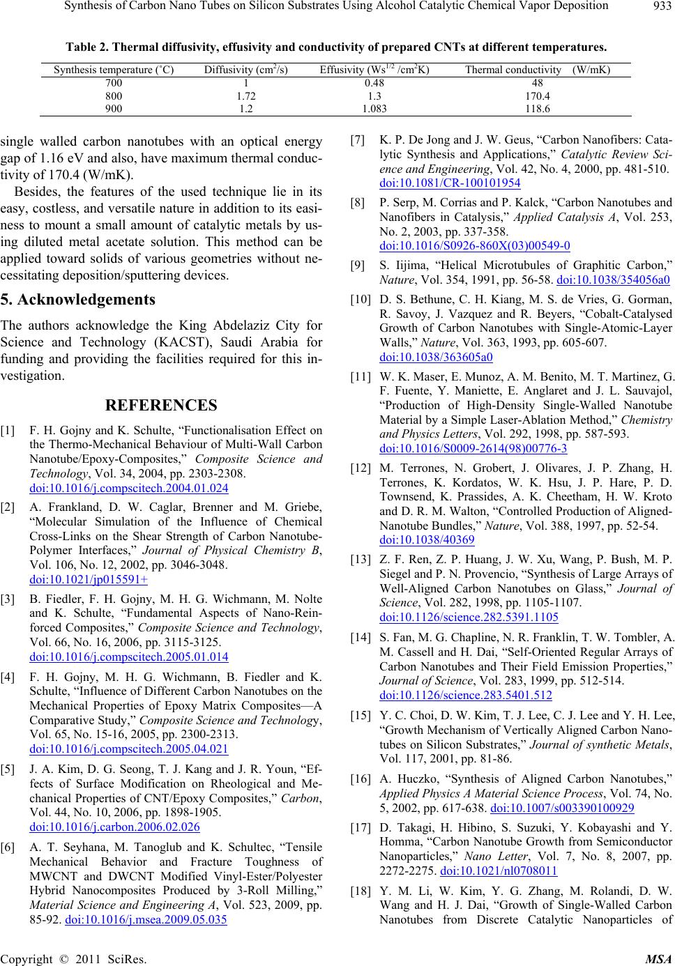 Synthesis of Carbon Nano Tubes on Silicon Substrates Using Alcohol Catalytic Chemical Vapor Deposition 933 Table 2. Thermal diffusivity, effusivity and conductivity of prepared CNTs at different temperatures. Synthesis temperature (˚C) Diffusivity (cm2/s) Effusivity (Ws1/2 /cm2K) Thermal conductivity (W/mK) 700 1 0.48 48 800 1.72 1.3 170.4 900 1.2 1.083 118.6 single walled carbon nanotubes with an optical energy gap of 1.16 eV and also, have maximum thermal conduc- tivity of 170.4 (W/mK). Besides, the features of the used technique lie in its easy, costless, and versatile nature in addition to its easi- ness to mount a small amount of catalytic metals by us- ing diluted metal acetate solution. This method can be applied toward solids of various geometries without ne- cessitating deposition/sputtering devices. 5. Acknowledgements The authors acknowledge the King Abdelaziz City for Science and Technology (KACST), Saudi Arabia for funding and providing the facilities required for this in- vestigation. REFERENCES [1] F. H. Gojny and K. Schulte, “Functionalisation Effect on the Thermo-Mechanical Behaviour of Multi-Wall Carbon Nanotube/Epoxy-Composites,” Composite Science and Technology, Vol. 34, 2004, pp. 2303-2308. doi:10.1016/j.compscitech.2004.01.024 [2] A. Frankland, D. W. Caglar, Brenner and M. Griebe, “Molecular Simulation of the Influence of Chemical Cross-Links on the Shear Strength of Carbon Nanotube- Polymer Interfaces,” Journal of Physical Chemistry B, Vol. 106, No. 12, 2002, pp. 3046-3048. doi:10.1021/jp015591+ [3] B. Fiedler, F. H. Gojny, M. H. G. Wichmann, M. Nolte and K. Schulte, “Fundamental Aspects of Nano-Rein- forced Composites,” Composite Science and Technology, Vol. 66, No. 16, 2006, pp. 3115-3125. doi:10.1016/j.compscitech.2005.01.014 [4] F. H. Gojny, M. H. G. Wichmann, B. Fiedler and K. Schulte, “Influence of Different Carbon Nanotubes on the Mechanical Properties of Epoxy Matrix Composites—A Comparative Study,” Composite Science and Technology, Vol. 65, No. 15-16, 2005, pp. 2300-2313. doi:10.1016/j.compscitech.2005.04.021 [5] J. A. Kim, D. G. Seong, T. J. Kang and J. R. Youn, “Ef- fects of Surface Modification on Rheological and Me- chanical Properties of CNT/Epoxy Composites,” Carbon, Vol. 44, No. 10, 2006, pp. 1898-1905. doi:10.1016/j.carbon.2006.02.026 [6] A. T. Seyhana, M. Tanoglub and K. Schultec, “Tensile Mechanical Behavior and Fracture Toughness of MWCNT and DWCNT Modified Vinyl-Ester/Polyester Hybrid Nanocomposites Produced by 3-Roll Milling,” Material Science and Engineering A, Vol. 523, 2009, pp. 85-92. doi:10.1016/j.msea.2009.05.035 [7] K. P. De Jong and J. W. Geus, “Carbon Nanofibers: Cata- lytic Synthesis and Applications,” Catalytic Review Sci- ence and Engineering, Vol. 42, No. 4, 2000, pp. 481-510. doi:10.1081/CR-100101954 [8] P. Serp, M. Corrias and P. Kalck, “Carbon Nanotubes and Nanofibers in Catalysis,” Applied Catalysis A, Vol. 253, No. 2, 2003, pp. 337-358. doi:10.1016/S0926-860X(03)00549-0 [9] S. Iijima, “Helical Microtubules of Graphitic Carbon,” Nature, Vol. 354, 1991, pp. 56-58. doi:10.1038/354056a0 [10] D. S. Bethune, C. H. Kiang, M. S. de Vries, G. Gorman, R. Savoy, J. Vazquez and R. Beyers, “Cobalt-Catalysed Growth of Carbon Nanotubes with Single-Atomic-Layer Walls,” Nature, Vol. 363, 1993, pp. 605-607. doi:10.1038/363605a0 [11] W. K. Maser, E. Munoz, A. M. Benito, M. T. Martinez, G. F. Fuente, Y. Maniette, E. Anglaret and J. L. Sauvajol, “Production of High-Density Single-Walled Nanotube Material by a Simple Laser-Ablation Method,” Chemistry and Physics Letters, Vol. 292, 1998, pp. 587-593. doi:10.1016/S0009-2614(98)00776-3 [12] M. Terrones, N. Grobert, J. Olivares, J. P. Zhang, H. Terrones, K. Kordatos, W. K. Hsu, J. P. Hare, P. D. Townsend, K. Prassides, A. K. Cheetham, H. W. Kroto and D. R. M. Walton, “Controlled Production of Aligned- Nanotube Bundles,” Nature, Vol. 388, 1997, pp. 52-54. doi:10.1038/40369 [13] Z. F. Ren, Z. P. Huang, J. W. Xu, Wang, P. Bush, M. P. Siegel and P. N. Provencio, “Synthesis of Large Arrays of Well-Aligned Carbon Nanotubes on Glass,” Journal of Science, Vol. 282, 1998, pp. 1105-1107. doi:10.1126/science.282.5391.1105 [14] S. Fan, M. G. Chapline, N. R. Franklin, T. W. Tombler, A. M. Cassell and H. Dai, “Self-Oriented Regular Arrays of Carbon Nanotubes and Their Field Emission Properties,” Journal of Science, Vol. 283, 1999, pp. 512-514. doi:10.1126/science.283.5401.512 [15] Y. C. Choi, D. W. Kim, T. J. Lee, C. J. Lee and Y. H. Lee, “Growth Mechanism of Vertically Aligned Carbon Nano- tubes on Silicon Substrates,” Journal of synthetic Metals, Vol. 117, 2001, pp. 81-86. [16] A. Huczko, “Synthesis of Aligned Carbon Nanotubes,” Applied Physics A Material Science Process, Vol. 74, No. 5, 2002, pp. 617-638. doi:10.1007/s003390100929 [17] D. Takagi, H. Hibino, S. Suzuki, Y. Kobayashi and Y. Homma, “Carbon Nanotube Growth from Semiconductor Nanoparticles,” Nano Letter, Vol. 7, No. 8, 2007, pp. 2272-2275. doi:10.1021/nl0708011 [18] Y. M. Li, W. Kim, Y. G. Zhang, M. Rolandi, D. W. Wang and H. J. Dai, “Growth of Single-Walled Carbon Nanotubes from Discrete Catalytic Nanoparticles of Copyright © 2011 SciRes. MSA  Synthesis of Carbon Nano Tubes on Silicon Substrates Using Alcohol Catalytic Chemical Vapor Deposition 934 Various Sizes,” Journal of Physics and Chemistry B, Vol. 46, No. 105, 2001, pp. 11424-11431. doi:10.1021/jp012085b [19] S. M. Bachilo, L. Balzano, J. E. Herrera, F. Pompeo, D. E. Resasco and R. B. Weisman, “Narrow nm-Distribution of Single-Walled Carbon Nanotubes Grown Using a Solid Supported Catalyst,” Journal of American Chemical So- ciety, Vol. 125, No. 37, 2003, pp. 11186-11187. doi:10.1021/ja036622c [20] Y. G. Zhang, A. L. Chang, J. Cao, Q. Wang, W. Kim, Y. M. Li, N. Morris, E. Yenilmez, J. Kong and H. J. Dai, “Electric-Field-Directed Growth of Aligned Single- Walled Carbon Nanotubes,” Applied Physics Letters, Vol. 79, 2001, pp. 3155-3157. doi:10.1063/1.1415412 [21] S. Huang, B. Maynor, X. Cai and J. Liu, “Ultralong, Well-Aligned Single-Walled Carbon Nanotube Architec- tures on Surfaces,” Journal of Advanced Materials, Vol. 15, 2003, pp. 1651-1655. doi:10.1002/adma.200305203 [22] W. E. Alvarez, B. Kitinayan, A. Borgna and D. E. Re- sasco, “Synergism of Co and Mo in the Catalytic Produc- tion of Single-Wall Carbon Nanotubes by Decomposition of CO,” Carbon, Vol. 39, No. 4, 2001, pp. 547-558. doi:10.1016/S0008-6223(00)00173-1 [23] B. Kitinayan, W. E. Alvarez, J. H. Harwell and D. E. Resasco, “Controlled Production of Single-Wall Carbon Nanotubes by Catalytic Decomposition of CO on Bi- metallic Co–Mo Catalysts,” Journal of Chemistry and Physics Letters, Vol. 317, 2000, pp. 497-503. [24] B. Zheng, Y. Li and J. Liu, “CVD Synthesis and Purifica- tion of Single-Walled Carbon Nanotubes on Aerogel- Supported Catalyst,” Journal of Applied Physics A Mate- rial Science Process, Vol. 74, No. 3, 2002, pp. 345-348. [25] P. Nikolaev, M. J. Bronikowski, R. K. Bradley, F. Roh- mund, D. T. Colbert, K. A. Smith and R. E. Smalley, “Gas-Phase Catalytic Growth of Single-Walled Carbon Nanotubes from Carbon Monoxide,” Journal of Chemis- try and Physics Letters, Vol. 31, 1999, pp. 91-97. doi:10.1016/S0009-2614(99)01029-5 [26] M. J. Bronikowski, P. A. Willis, D. T. Colbert, K. A. Smith and R. E. Smalley, “Gas-Phase Production of Car- bon Single-Walled Nanotubes from Carbon Monoxide via the HiPco Process: A Parametric Study,” Journal of Vac- uum Science and Technology A, Vol. 19, No. 4, 2001, pp. 1800-1805. doi:10.1116/1.1380721 [27] S. Maruyama, R. Kojima, Y. Miyauchi, S. Chiashi and M. Kohno, “Low-Temperature Synthesis of High-Purity Sin- gle-Walled Carbon Nanotubes from Alcohol,” Journal of Chemistry and Physics Letters, Vol. 360, 2002, pp. 229- 234. doi:10.1016/S0009-2614(02)00838-2 [28] Y. Murakami, Y. Miyauchi, S. Chiashi and S. Maruyama, “Characterization of Single-Walled Carbon Nanotubes Catalytically Synthesized from Alcohol,” Journal of Che- mistry and Physics Letters, Vol. 374, 2003, pp. 53-58. [29] Y. Murakami, Y. Miyauchi, S. Chiashi and S. Maruyama, “Direct Synthesis of High-Quality Single-Walled Carbon Nanotubes on Silicon and Quartz Substrates,” Journal of Chemistry and Physics Letters, Vol. 377, 2003, pp. 49-54. [30] S. Ma ruyama, Y. Miyauchi, T. Edamura, Y. Igarashi, S. Chiashi and Y. Murakami, “Synthesis of Single-Walled Carbon Nanotubes with Narrow Diameter-Distribution from Fullerene,” Journal of Chemistry and Physics Let- ters, Vol. 375, 2003, pp. 553-559. doi:10.1016/S0009-2614(03)00907-2 [31] Y. Murakami, S. Chiashi, Y. Miyauchi, M. Hu, M. Ogura, T. Okubo and S. Maruyama, “Growth of Vertically Aligned Single-Walled Carbon Nanotube Films on Quartz Substrates and Their Optical Anisotropy,” Journal of Chemistry and Physics Letters, Vol. 385, 2004, pp. 298-303. doi:10.1016/j.cplett.2003.12.095 [32] S. Maruyama, E. Einarsson, Y. Murakami and T. Eda- mura, “Growth Process of Vertically Aligned Single- Walled Carbon Nanotubes,” Journal of Chemistry and Physics Letters, Vol. 403, 2005, pp. 320-323. doi:10.1016/j.cplett.2005.01.031 [33] T. Okazaki and H. Shinohara, “Synthesis and Characteri- zation of Single-Wall Carbon Nanotubes by Hot-Filament Assisted Chemical Vapor Deposition,” Journal of Chem- istry and Physics Letters, Vol. 376, 2003, pp. 606-611. doi:10.1016/S0009-2614(03)01042-X [34] S. Chiashi, Y. Murakami, Y. Miyauchi and S. Maruyama, “Cold wall CVD Generation of Single-Walled Carbon Nanotubes and in Situ Raman Scattering Measurements of the Growth,” Journal of Chemistry and Physics Letters, Vol. 386, 2004, pp. 89-94. doi:10.1016/j.cplett.2003.12.126 [35] D. Nishide, H. Kataura, S. Suzuki, O. Okubo and Y. Achiba, “Growth of Single-Wall Carbon Nanotubes from Ethanol Vapor on Cobalt Particles Produced by Pulsed Laser Vaporization,” Journal of Chemistry and Physics Letters, Vol. 392, 2004, pp. 309-313. doi:10.1016/j.cplett.2004.04.119 [36] H. E. Unalan and M. Chhowalla, “Investigation of Single- Walled Carbon Nanotube Growth Parameters Using Al- cohol Catalytic Chemical Vapour Deposition,” Nano- technology, Vol. 16, 2005, pp. 2153-2163. doi:10.1088/0957-4484/16/10/031 [37] S. M. Sze, “Physics of Semiconductor Devices,” 2nd Edition, Wiley, New York, 1981. [38] K. L. Chopra, R. C. Kainthla, D. K. Pandya and A. P. Thakoor, “Physics of Thin Films,” Academic Press, New York. Vol. 12, 1982, p. 169 [39] S. Al-Ani, I. Al-Hassany, Z. Al-Dahan, “The Optical Properties and A. C. Conductivity of Magnesium Phos- phate Glasses,” Journal of Material Science, Vol. 30, 1995, pp. 3720-3726. doi:10.1007/BF00351890 [40] Khairurrijal, M. Abdullah, M. Rosi and A. N. Fatimah, “Structural Characteristics of Carbon Nanotubes Fabri- cated Using Simple Spray Pyrolysis Method,” Indonesian Journal of Physics, Vol. 19, No. 3, 2008, pp. 91-95. [41] Y. Huang, N. Li, Y. Ma, F. Du, F. Li, X. He, X. Lin, H. Gao and Y. Chen, “The Influence of Single-Walled Car- bon Nanotube Structure on the Electromagnetic Interfer- ence Shielding Efficiency of Its Epoxy Composites,” Carbon, Vol. 45, 2007, pp. 1614-1621. Copyright © 2011 SciRes. MSA  Synthesis of Carbon Nano Tubes on Silicon Substrates Using Alcohol Catalytic Chemical Vapor Deposition Copyright © 2011 SciRes. MSA 935 [42] I. Stamatina, A. Morozana, A. Dumitrua, V. Ciupinab, G. Prodanb, J. Niewolskic, H. Figielc, “The Synthesis of Multi-Walled Carbon Nanotubes (MWNTs) by Catalytic Pyrolysis of the Phenol-Formaldehyde Resins,” Physica E, Vol. 37, 2007, pp. 44-48. doi:10.1016/j.physe.2006.10.013 [43] M. S. Jeong and C. C. Byeon, “Purity Measurement of Single Walled Carbon Nanotubes by UV-Vis-NIR Ab- sorption Spectroscopy and Thermogravimetric Analysis,” Nano, Vol. 3, No. 2, 2008, pp. 101-108. doi:10.1142/S1793292008000885 [44] D. Y. Kim, Y. S. Yun, H. Bak, S. Y. Cho and H. J. Jin, “Aspect Ratio Control of Acid Modified Multiwalled Carbon,” Current Applied Physics, Vol. 10, 2010, pp. 1046-1052. doi:10.1016/j.cap.2009.12.038 [45] D. Chen, T. Sasaki, J. Tang and L. C. Qin, “Effects of Deformation on the Electronic Structure of a Single- Walled Carbon Nanotube Bundle,” Physical Review B, Vol. 77, 2008, p. 125412. doi:10.1103/PhysRevB.77.125412 [46] A. S. Ayesh and R. Abed Al-Rahem, “Optical and Elec- trical Properties of Polycarbonate/MnCl2 Composite Films,” Journal of Plastic Films and Sheeting, Vol. 24, No. 2, 2008, pp. 109-124. doi:10.1177/8756087908094854 [47] T. A. El-Brolossy, S. Abdallah, T. Abdallah, H. Awad, M. B. Mohamed, S. Negm and H. Talaat, “Photoacoustic Spectroscopy Characterization of CdSe Quantum Rods,” European Physics Journal Special Topics, Vol. 153, 2008, pp. 369-372. doi:10.1140/epjst/e2008-00464-x [48] J. Hone, M. Whitney, C. Piskoti and A. Zettl, “Thermal Conductivity of Single-Walled Carbon Nanotubes,” Physical Review B, Vol. 59, 1999, pp. R2514-R2516. doi:10.1103/PhysRevB.59.R2514 [49] J. Hone, M. C. Llaguno, N. M. Nemes, A. T. Johnson, J. E. Fischer, D. A. Walters, M. J. Casavant, J. Schmidt and R. E. Smalley, “Electrical and Thermal Transport Proper- ties of Magnetically Aligned Single Wall Carbon Nano- tube Films,” Applied Physics Letters, Vol. 77, 2000, pp. 666-669. doi:10.1063/1.127079 [50] G. D. Zhan and A. K. Mukherjee, “Processing and Char- acterization of Nanoceramic Composites with Interesting Structural and Functional Properties,” Review of Ad- vanced Material Science, Vol. 10, 2005, pp. 185-191.
|