Materials Sciences and Applicatio n, 2011, 2, 878-890
doi:10.4236/msa.2011.27118 Published Online July 2011 (http://www.SciRP.org/journal/msa)
Copyright © 2011 SciRes. MSA
Finite Element Wear Behavior Modeling of
Al/Al2SiO5/C Chilled Hybrid Metal Matrix
Composites (CHMMCs)
Joel Hemanth
Rajiv Gandhi Institute of Technology, Bangalore, Karnataka, India.
E-mail: joelhemanth@hotmail.com
Received July 8th, 2010; revised August 12th, 2010; accepted May 21st, 2011.
ABSTRACT
This paper describes research on aluminum based metal matrix hybrid composites reinforced with kaolinite (Al2SiO5)
and carbon (C) particulates cast using high rate heat transfer technique during solidification by employing metallic,
non-metallic and cryogenic end chills. The effect of reinforcement and chilling on strength, hardness and wear behavior
are discussed in this paper. It is discovered that cryogenic chilled MMCs with Al2SiO5-9 vol.%/C-3 vol.% dispersoid
content proved to be the best in enhancing the mechanical and wear properties. A physically based Finite element (FE)
model for the abrasive wear of the hybrid composite developed is based on the mechanisms associated with sliding
wear of ductile aluminum matrix of the composite containing hard Al2SiO5 and soft carbon (dry lubricant) reinforce-
ment particles. Finally the results reveal that there is a good agreement that exists between the simulated (FE) values
and those of the experimental valu es, proving the suitability of the boundary conditions.
Keywords: Aluminum, Composites, Casting, Hybrid and Wear
1. Introduction
Reinforced hybrid metal matrix composites (HMMC),
constituted of high-strength metallic alloys reinforced
with two dispersoids are advanced materials that have
emerged from the perpetual need of lighter-weight,
higher-performance components more recently used in
automotive applications. Indeed, these new materials
offer promising perspectives in assisting automotive en-
gineers to achieve improvement in vehicle fuel efficiency.
Their destructive properties of high stiffness, high
strength and low density have prompted an increasing
number of applications for these materials. Several of
these applications require enhanced friction and wear
performances.
Wear of components is often a critical factor influenc-
ing the product service life and most confident knowl-
edge about the friction pair tribological behavior can be
achieved by making wear experiments. Wear takes place
when surfaces of mechanical components contact each
other hence its prediction is therefore an important part
of engineering. In order to predict wear and eventually
the life-span of complex mechanical systems, several
hundred thousand operating cycles have to be simulated.
Hence, wear and the calculation of wear between sur-
faces in contact has not been a concern in the finite ele-
ment realm. Therefore finite element (FE) post-processor
is the optimum choice, considering the computational
expense. Therefore a FE software MSC-Marc has been
used in this research to initiate a discussion of a proce-
dure for calculat ion of wear.
Hence the objective of this research is twofold, first to
develop chilled hybrid MMC using kaolinite (Al2SiO5, a
hard ceramic) and carbon (dry lubricant) as reinforce-
ments, second to analyze the wear performance of the
hybrid MMC developed experimentally as well as by FE
modeling.
2. Literature Review
In recent years there has been a great deal of interest in
developing metal matrix composites (MMC) because of
their unique mechanical properties such as light weight
and high elastic modulus. The common fabrication routes
of particulate reinforced MMCs include spray de position,
liquid metallurgy and powder metallurgy [1,2]. Since
expensive equipment is required and the processing
routes are usually complex, the cost to produce MMCs
by these methods is high, which has limited the applica-
Finite Element Wear Behavior Modeling of Al/AlSiO /C Chilled Hybrid Metal Matrix Composites (CHMMCs)879
2 5
tions of MMC materials. Presently, the bonding tech-
nique of hot and cold rolling process developed to fabri-
cate particular reinforced MMCs involves complexities
[3-7]. Several other processes used to produce discon-
tinuous MMCs also include rheocasting, compocasting
and squeeze casting [8-11]. Many reports on the charac-
terization of mechanical properties of discontinuous
MMCs have been available [12-15]. According to them,
mechanical properties such as Young’s modulus and
strength, have been improved about 20% - 40% by in-
corporation of reinforcements. However, ductility has
deteriorated remarkably with increasing content of rein-
forcements [16-18]. There are many micro structural
variables, such as the ageing condition of the matrix al-
loy, the material used as reinforcement, the volume frac-
tion and the size of the particulates, and each of these
may effect the mechanical properties of the composite
[19-21]. Reinforcing an Al alloy with particulates yields
a composite that displays the superior physical and me-
chanical properties of both the metal matrix and the dis-
persoid. On a weight-adjusted basis, many Al-based
metal matrix composites (MMCs) can outperform cast
steel, Al, Mg and virtually any other reinforced metal or
alloy in a wide variety of applications. Hence, it seems
probable that such MMCs will replace conventional ma-
terials in many commercial and industrial app lications in
the near future [22-25].
Wear is an important in any structure subjected to re-
peated loadings and may be critical for certain tribologi-
cal applications. In this research, a proper procedure is
proposed whereby the effects of wear may be calculated
and included in the overall analysis of the structure. The
famous Archard equation is used as the basis for calcu-
lating wear strain which is used to modify the elastic
strain of an element in an explicit manner [26].
A wear simulation approach based on Archards wear
law is implemented in an FE p ost pro cessor that work s in
association with commercial FE package MSC-Marc for
solving the general deformable contact problems. Here
local wear is computed and then integrated over the slid-
ing distance using the Euler integration scheme. The
wear simulation tool works with FE simulation with sur-
face geometries to get realistic contact pressure distribu-
tion on the contacting surfaces. The wear on both the
interacting surfaces are computed using the contact
pressure distri b uti on [2 7-29].
It is well known that Al alloys that freeze over a wide
range of temperature are difficult to feed during solidifi-
cation. The dispersed porosity caused by the pasty mode
of solidification can be effectively reduced by the use of
chills. Chills extract heat at a faster rate and promote
directional solidification. Therefore chills are widely
used by foundry engineers for the production of sound
and quality castings. There have been several investiga-
tions [30-32] on the influence of chills on the solidifica-
tion and soundness of alloys. With the increase in the
demand for quality composites, it has become essential to
produce Al composites f ree from unsoundness.
Search of open literature indicates that, so for number
of Al based MMCs including chilled MMCs are being
developed but no work has been done in this field. Hence
the present research is underaken to fill the void and to
investigate the integrated properties of chilled Al-alloy/
Al2SiO5/C HMMCs. Among all the reinforcementsused
in Al based composites only combination of particulates
and chilling in the present investigation has shown their
potential superiority in improving mechanical properties,
microstructure with noticeable weight savi n g s.
Relevance of the Research
In this research both experimental and Finite Element
(FE) modeling is developed that are used to identify the
abrasive wear of the composite developed. This FE
software (MSC Marc) is well suited for solving of con-
tact problems as well as the wear simulation. Here, a
pin on disc un-lubricated contact was analyzed experi-
mentally with FE modeling. This model is based on the
assumption that any portion of the reinforcement that is
removed as wear debris cannot contribute to the wear
resistance of the composite material developed. Critical
variables describing the role of the reinforcement such as
relative size, hardness and nature of the matrix mate-
rial/reinforcement interface are characterized. Predictions
are compared with the results of experimental two body
(pin on disc) abrasive wear tests performed on a model
developed.
3. Experimental Procedure
3.1. Fabrication of Al/Al2SiO5/C Hybrid Chilled
MMCs
The chemical composition of the aluminum alloy (LM 13)
used as the matrix material is given in Table 1.
In this investigation, the amount of Al2SiO5/C particu-
lates dispersed in the matrix are Al2SiO5-3/C-3 vol.%,
Al2SiO5-6/C-3 vol.%, Al2SiO5-9/C-3 vol.% and Al2SiO5-
12/C-3 vol.% (combination of dispersoid varies from 3 to
12 vol% in steps of 3% of Al2SiO5) respectively. The
size of Al2SiO5/C particulates dispersed is between 30
and 80 m. After melting the matrix material in a furnace
at around 720˚C in an inert atmosphere, Al2SiO5 and C
particulates preheated to 600˚C were introduced evenly
into the molten metal alloy by means of special feeding
(sandwich technique) attachments. The melt was next
poured into a sand mould containing different chills
(each 25 mm thick) attached to it at one end. Sub zero
copper end chill of thickness 25 mm was used in which
Copyright © 2011 SciRes. MSA
Finite Element Wear Behavior Modeling of Al/AlSiO /C Chilled Hybrid Metal Matrix Composites (CHMMCs)
880 2 5
Table 1. Chemical composition of matrix material (Al-alloy LM 13).
Elements Zn Mg Si Ni Fe Mn Al
% by wt 0.5 1.4 12 1.5 1.0 0.5 Bal
arrangements were made to circulate liquid nitrogen (at
–90˚C) to study the effect of heat capacity on mechanical
and micro structural behavior. The ch ills used were 170
mm long, 35 mm high and 25 mm thick. The moulds
were produced according to AFS standards of dimension
225 × 150 × 25 mm. Specimens for all the tests were se-
lected only at the chill end of the casting and all the
specimens were heat-treated by aging before testi ng.
Chills used: 1. Sub zero copper chill
2. Metallic chill (copper)
3. Non metallic chill (graphite)
3.2. Properties of Dispersoid: Al2SiO5 (Kaolinite)
Density: 3.9 gm/cc, Hardness: 430 BHN, Chemical for-
mula: Al2SiO5
Melting point: 2050˚C, Space group: P1 Triclinic,
Young’s modulus: 89 GPa,
Chemical composition: SiO2, Al2O3, Fe2O3, TiO2,
MgO.
3.3. Testing Procedure
Microscopic examination was conducted on all the
specimens using scanning electron microscope (SEM) as
well as using Neophot-21 metallurgical microscope. Dry
wear tests were conducted at room temperature as per
ASTM D5963-97 standards using the computerized pin
on disc wear tester manufactured by Riken-Ogoshi & Co.,
Korea. The studied configuration is a pin of 6 mm di-
ameter on plane contact, where as the plane is the AISI
5210 steel. Wear tests using volume loss method were
performed at different loads (10 to 50 N in steps of 10 N)
for a time period of 300 seconds. Hardness and strength
tests (on AFS standard tensometer specimen) were per-
formed using Vickers hardness tester and Instron testing
machine.
3.4. Pin on Disc FE Model for Wear Testing
The model presented in this research (refer Figure 1)
consists of two bodies, the lower one is a rotating disc
(AISI 52100) steel and top of it is a rigid body (pin of 6
mm diameter) contact surface. The rigid contact surface
is used to apply the load to the rotating surface. Here the
famous Archard [33] approach taking into account the
wear process is introduc ed to formalize the wear kinetics.
This model is developed based on equal and steady state
wear rate assumption with simplified geometry in which
abrasive medium particle acting on composite containing
reinforcements.
Here the analysis is performed in three load steps: 1)
Figure 1. Pin on disc model for measuring wear rate.
Displacement of the pin to generate the contact 2) The
load step which converts displacement to load after con-
tact has been establishe d and 3) The static loading step in
which a group of load steps each with an incremental
time that represents the rep etition of the load to calculate
the wear over a time period.
In this investigation, predictions are compared with the
results of experimental two-body (pin on disc) abrasive
wear tests performed on the same chilled Al2SiO5/C
MMC specimen.
4. Results and Discussion.
In the present investigation, of all the chills, sub zero
copper end chill was found to be the most effective be-
cause of its high VHC. Dispersoid content up to
Al2SiO5-9/C-3 vol.% was found to increase the mechani-
cal properties (strength and hardness) and therefore it is
considered to be the optimum limit. Hence the present
discussion is mainly focused on sub zero copper chilled
MMC with Al2SiO5-9 /C-3 vol.% dispersoid content
4.1. Micro Structural Studies
Figures 2(a-c) show the microstructure of chilled hybrid
MMCs containing Al2SiO5-9/C-3 vol.% dispersoid, cast
using different chills. Micro structural examination of
chilled MMCs is discussed in terms of distribution of
reinforcement and reinforcement matrix interfacial
bonding. It is observed from these figures that for all the
chilled MMCs there is a uniform distribution of disper-
soid and good bonding with the matrix. Micro structural
studies conducted on the composite containing Al2SiO5-9/
Copyright © 2011 SciRes. MSA
Finite Element Wear Behavior Modeling of Al/AlSiO /C Chilled Hybrid Metal Matrix Composites (CHMMCs) 881
2 5
(a) (b)
(c) (d)
Figure 2. Microstructure of chilled hybrid MMCs containing Al2SiO59/C-3 vol.% dispersoid, cast using different chills. (a)
Graphite chilled MMC; (b) Copper chilled MMC; (c)Sub zero chilled MMC; (d) SEM fractograph of hybrid MMC contain-
ing Al2SiO5-9/C-3 vol.% dispersoid, cast using sub zero chill.
C-3 vol.% dispersoid content cast using sub zero chill
revealed limited extent of clusters, good reinforce-
ment-matrix interfacial integrity, and significant grain
refinement with minimal porosity (Figure 2(c)). This is
due to gravity of Al2SiO5 particulates associated with
judicious selection of stirring parameters (vortex route),
good wetting of pre heated reinforcement by the matrix
melt. Figures 2(a,b) show graphite and copper chilled
MMCs in which there is an increase in the size of the
grains and of course with uniform distribution of the
dispersoid. Grain reinforcement in all these chilled hy-
brid composites can primarily be attributed to capability
of Al2SiO5 and carbon particulates to nucleate aluminum
grains during directional solidification and restricted
growth of recrystallized aluminum grains because of
presence of finer reinforcement and chilling. Interfacial
integrity between matrix and the reinforcement was
assessed using scanning electron microscope of the
fractured surface (Figure 2(d)) to analyze the interfa-
cial de-bonding at the particulate-matrix interface. Here
also the result revealed that a strong bond exists be-
tween the interfaces as expected from metal/oxide sys-
tems [34].
Micro and macro tests conducted on chilled MMCs
reveal that, high rate heat transfer during solidification
(i.e., effect of chilling) of the composite in this investiga-
tion leads to stronger bond between dispersoid and the
matrix. This may be one of the main reasons for in crease
of strength, hardness and wear resistance of the compos-
ite developed. The result of micro structural studies of
chilled MMCs however did not reveal presence of any
micro-pores or shrinkage cavity.
4.2. Heat Treatment and Hardness
All the test samples before mechanical testing were sub-
ject to aging process. Therefore, if all other factors are
kept constant, the aging rate of a composite is generally
faster than that of the matrix alloy [35]. After solution
treatment, optimum aging conditions can be determined
by observing the h ardness of the MMCs cast using chills
for different aging durations. It is known that the opti-
mum aging conditions are strongly dependent upon the
amount of dispersoid present [36]. It can be seen that for
each MMC, as the aging time increases, the hardness of
the MMCs increases to a peak value and then drops again.
As Al2SiO5/C content is increased, there is a tendency for
the peak aging time to be reduced because dispersoids
provide more nucleation sites for precipitation. As ex-
pected, for any fixed aging temperature and duration,
increasing the Al2SiO5/C content causes the hardness of
the MMC to increase since Al2SiO5/C combination of
particulates are so much harder than the aluminum alloy
matrix.
Figure 3 shows hardness of chilled hybrid MMCs cast
using various types of chills. The results of micro hard-
ness test (HV) conducted on chilled MMCs samples re-
vealed an increasing trend in matrix hardness with an
increase in reinforcement content (up to 9 vol%). Results
of hardness measurements also revealed that the type of
chill has an effect on hardness of the composite. This
Copyright © 2011 SciRes. MSA
Finite Element Wear Behavior Modeling of Al/AlSiO /C Chilled Hybrid Metal Matrix Composites (CHMMCs)
882 2 5
Figure 3. Hardness Vs dispersoid content of chilled hybrid MMCs.
significant increase in the hardness can be attributed
primarily to presence of harder Al2SiO5 ceramic particu-
lates in the matrix, a higher constraint to the localized
deformation during indentation due to their presence and
reduced grain size due to chilling. In ceramic-reinforced
composite, there is generally a big difference between the
mechanical properties of the dispersoid and those of the
matrix. These results in incoherence and a high density
of dislocations near the interface between the dispersoid
and the matrix [37]. Precipitation reactions are acceler-
ated because of incoherence and the high density of dis-
locations act as heterogeneous nucleation sites for pre-
cipitation [38].
4.3. Ultimate Tensile Strength (UTS) of the
Composite
Figure 4 shows the effect of dispersoid content on UTS
for various MMCs cast using different types of chills of
thickness 25 mm. It is observed that UTS is again maxi-
mum for the hybrid composite containing Al2SiO5-9/C-3
vol.% cast using sub zero chill. Further, it may be ob-
served from Figure 4 that, the effect of increasing the
VHC of the chill increases UTS. In most cases, ceramic
reinforced MMCs have superior mechanical properties to
the un-reinforced matrix alloy because these MMCs have
high dislocation d ensities due to disocation generation as
a result of differences in coefficient of thermal expansion
[39]. As in the study however, with the incorporation of
carbon particulates aimed at improving wear property has
little effect on mechanical properties i.e., UTS and hard-
ness is due to addition of combination of dispersoids.
However, in a hybrid composite, UTS and hardness of
Al/Al2SiO5/C are slightly increased by increasing the
addition of Al2SiO5 particulates. This shows that, carbon
additions were seen to be less effective in strengthening
than Al2SiO5 particulates alone. It can be considered that
carbon particulates in the hybrid system wet with the
molten aluminum alloy and also react with the matrix
alloy to form hard and brittle aluminum carbide (Al4C3)
at high temperatures. From the results, the mechanical
characterization of chilled Al/Al2SiO5/C hybrid MMCs
can be summarized as follows: Carbon particulates have
little effect on tensile properties but has more effect on
wear behavior, where as Al2SiO5/C contributes for
strength, h ard ness as we ll as for wear.
4.4. Experimental Analysis of Wear Behavior
Figure 5 shows the effect of load on the wear rate of
matrix alloy and different chilled hybrid Al/Al2SiO 5/C
MMCs. It can be seen from these figures that as the load
and dispersoid content increases, the wear rate of the
composite improves remarkably. It is observed from Fig-
ure 5(a) that the matrix alloy exhibits the highest wear
due to its low hardness followed by graphite, copper and
sub zero chilled MMCs in that order. It is also noticed
from these figures that, increasing the dispersoid content
up to Al2SiO5-9 vol.%/C-3 vol.% (addition beyond this
limit deteriorate the properties) leads to a sharp reduction
in wear rate. Therefore, the increased wear resistance of
the composite, reinforced with Al2SiO 5/C is attribu ting to
the increase of hardness and UTS of the matrix phase and
the low wear of Al2SiO5 particles. The abrasive wear
mechanism described by Rabinowicz [40] and sliding
wear due to adhesion given by Archard [41] both indicate
that the wear rate depends on th e hardness of the material
i.e., volumetric loss of the material is inversely propor-
Copyright © 2011 SciRes. MSA
Finite Element Wear Behavior Modeling of Al/AlSiO /C Chilled Hybrid Metal Matrix Composites (CHMMCs)883
2 5
tional to the hardness value of the material. The experi-
mental data of this research work as shown in Figures
5(a-d) and Figure 3 (hardness plot) correlate well with
Rabi-nowicz wear mechanism.
Also from Figure 5(d) it is seen that the wear rate for
sub zero chilled MMC containing Al2SiO5-9/C-3 vol.%
Figure 4. Strength Vs dispersoid content of chilled hybrid MMCs.
(a)
(b)
Copyright © 2011 SciRes. MSA
Finite Element Wear Behavior Modeling of Al/AlSiO /C Chilled Hybrid Metal Matrix Composites (CHMMCs)
884 2 5
(c)
(d)
Figure 5. Wear rate Vs load of matrix alloy and different chilled hybrid MMCs. (a) Plot of wear rate Vs load (Matrix alloy);
(b) Plot of wear rate Vs load (G raphite chill ed MMCs); (c) Plot of we ar r ate Vs load (Cu chilled MMCs); (d) Plot of wear rate
Vs load (Sub zero chilled MMCs).
dispersoid tested at loads 10, 30 and 50 N are respec-
tively 0.0025, 0.0074 and 0.009. This checks well with
FE predictions as shown in Figures 7 (a-c) and 8 (a-c).
Figures 6 (a,b) show typical SEM photographs of the
worn surfaces of hybrid composite containing Al2SiO5-
9%/C-3 vol.% and Al2SiO5-6/C-3 vol.% dispersoid con-
tent cast using sub zero ch ill tested at a lo ad of 10 N fo r a
time period of 300 second s. At low er load s (10 and 20 N)
the major wear mechanisms of the chilled composite are
abrasive and adhesive wear, during which the MMC is
worn by the frictional force on the wear surface [42]. At
this load it was found that ab rasive wear was dominant in
ploughing and grooving as indicated in Figures 6 (a,b).
It observed that at 10 N load, the MMC with Al2SiO5-9/
C-3 vol.% has grooves formed (Figure 6(a)) by the
shearing action of the friction on the wear surface. In fact,
even the wear surface of the MMC with Al2SiO5-6/C-3
vol.% dispersoid contains a number of deep wear
grooves (Figure 6(b)).
The worn surfaces of the sub zero chilled hybrid MMC
containing Al2SiO5-9/C-3 vol.% and Al2SiO5-6/C-3
vol.% dispersoid co ntent tested at an intermediate load of
30 N are shown in Figures 6(c) and 6(d). The wear de-
bris and distorted surface of the MMC with
Al2SiO5-6/C-3 vol.% dispersoid content are more distinct
than those in the MMC with Al2SiO5-9/C-3 vol.% dis-
persoid content. From the wear surface, it can be seen
that the wear debris and distorted surface play an impor-
tant role on the wear, which increases with their forma-
tion and growth. The distorted surface and debris are
formed at the locally fractured area of the matrix alloy.
This localized fracture is ceased by highly localized fric-
tional forces between the non-uniform surface of the
counter material and the defective areas on the wear sur-
face. The wear surface of MMC having Al2SiO5-6/C-3
vol.% dispersoid content shows severe (see arrow in
Copyright © 2011 SciRes. MSA
Finite Element Wear Behavior Modeling of Al/AlSiO /C Chilled Hybrid Metal Matrix Composites (CHMMCs) 885
2 5
(a) (b)
(b) (d)
(e) (f)
Figure 6. SEM photographs of sub zero chilled hybrid MMCs tested at different loads. (a) SEM photograph of Al2SiO5-9/ C-3
vol.% sub zero chilled MMC tested at 10 N; (b) SEM photograph of Al2SiO5-6/ C-3 vol.% sub zero chilled MMC tested at 10
N; (c) SEM photograph of Al2SiO5-9/ C-3 vol.% sub zero chilled MMC tested at 30 N; (d) SEM photograph of Al2SiO5-6/ C-3
vol.% sub zero chilled MMC tested at 30 N; (e) SEM photograph of Al2SiO5-9/ C-3 vol. % sub zero chilled MMC tested at 50
N; (f) SEM photograph of Al2SiO5-6/ C-3 vol. % sub zero chilled MMC tested at 50 N.
(a)
Copyright © 2011 SciRes. MSA
Finite Element Wear Behavior Modeling of Al/Al2SiO5/C Chilled Hybrid Metal Matrix Composites (CHMMCs)
Copyright © 2011 SciRes. MSA
886
(b)
(c)
Figure 7. (a) Wear Rate (0.00225) of Al2SiO5-9/C-3 vol.% sub zero chilled MMC for 10 N load; (b) Wear Rate (0.00744) of
Al2SiO5-9/C-3 vol.% sub zero chilled MMC for 30 N load; (c) Wear Rate (0.00929) of Al2SiO5-9/C-3 vol.% sub zero chilled
MMC for 50N load.
Figure 6(d)) abrasive and adhesive wear which is the
dominant wear mechanisms at intermediate load. By
contrast, the wear surface of the MMC with Al2SiO5-9/
C-3 vol.% dispersoid content is completely different in
that on this surface, abrasive wear is hardly seen (wave
like pattern) and this is due to the reduction in frictional
forces on the wear surface. Visible lack of da mage in both
cases (low and intermediate load) is due to the presence of
solid lubrication film formed by the addition of carbon
particulates on the wear surface of hybrid composites.
Consequently, this result gives rise to the improvement of
wear resistance.
Testing of the chilled MMCs at a final load of 50 N
(higher load), however, the major wear mechanism
changes to melt wear because of the rise in temperature
on the localized wear surface, resulting in the MMCs
being worn out less rapidly. At this load the adhesive and
slip phenomena also appear (see Figure 6(e)). Here, the
solid lubricant behavior of carbon makes adhesive wear
to be dominant at high sliding speeds. This can be deter-
Finite Element Wear Behavior Modeling of Al/AlSiO /C Chilled Hybrid Metal Matrix Composites (CHMMCs)887
2 5
mined by removed materials and slip phenomena that are
found in the wave patterns of materials. The removal of
the material seems to be accelerated by fractures of
Al2SiO5/C particulates and the matrix which might be
due to the high frictional force on the wear surface. Worn
surfaces of Al2SiO5-9/C-3 vol.% and the Al2SiO5-6/C-3
vol.% sub zero chilled MMCs tested at a final load of 50
N are shown in Figures 6(e) and 6(f) respectively. Lo-
calized melted areas (see arrow in Figure 6(f)) owing to
the rise in temperature can be seen in composite contain-
ing Al2SiO5-6/C-3 vol.% dispersoid. As show n in Figure
6(f), wear of the Al2SiO5-6/C-3 vol.% disperso id content
chilled composite seems to start by localized melting of
the surface and proceed by delaminations from the ma-
trix in which there is severe plastic deformation. In
Al2SiO5-9/C-3 vol.% chilled composite shown in Figure
6(e), some wave-like wear patterns can be seen which
might be related to melt and slip.
4.5. Finite Element Analysis of Wear
MSC Marc software used in the present analysis is
equipped with the energy error estimation technique,
based on the fact that the FEM structural analysis results
in a continuous displacement field from element to
(a)
(b)
Copyright © 2011 SciRes. MSA
Finite Element Wear Behavior Modeling of Al/AlSiO /C Chilled Hybrid Metal Matrix Composites (CHMMCs)
888 2 5
(c)
Figure 8. Plot of wear rate Vs increment load for Al2SiO5-9/C-3 vol.% sub zero chilled MMC tested at different loads. (a)
Wear Rate Vs Increment load (10 N) ×of Al2SiO5-9/C-3 vol.% sub zero chilled MMC; (b) Wear Rate Vs Increment load (30
N) of Al2SiO5-9/C-3 vol.% sub zero chilled MMC; (c) Wear Rate Vs Increment load (50 N) of Al2SiO5-9/C-3 vol.% sub zero
chilled MMC.
element, but a discontinuous stress field. To obtain more
acceptable stress, the elemental nodal stresses are aver-
aged. The nodal stress error vectors are accordingly
evaluated, being a base for the energy error estimation
for elements and over the entire model. When the energy
errors are equal for every element, then that particular
model with its given discretisation is the most effective
one.
Perhaps the most convincing way to verify the FEM
results is to compare them with the known experimental
results. The wear of the pin on disc configuration, Figure
1, was analyzed with the FEM approach outlined above.
Figures 7(a-c) show the evolution of the developed
stresses along the sliding direction at different stages of
loading as the wear progresses and Figure 8 shows the
wear rate plot. Since we assume that wear is dependent
upon stress and the stress values are changing over time
due to the wear and the changing contact, then wear at
any particular location is ch anging over time. This can be
seen from the contact pressure at different loads repre-
senting different amounts of wear as in Figures 7(a-c).
In the current configuration, wear is calculated as an up-
date to the state of strain at the end of each sub step. The
incremental wear strain would be calculated and would
be added to the previously calculated wear strain. Note
that changing the loads will require the changing the
boundary conditions. The progressive decrease in the
contact pressure as the sliding progresses can be qualita-
tively compared with the ring-on ring case shown in
Figures 7(a-c). However, in the pin-on-disc problem
there is a difference in the stress distribution along the
sliding direction due to the non-axi-symmetric boundary
conditions. This stress distribution is a result of the co ef-
ficient and cannot be ignored for the computation of wear.
Figures 8(a-c) show the graph of wear rate plotted
against incremental load perpendicular to the sliding di-
rection. The shape of the particular wear curve for a
given contact geometry and loading is determined by the
change of the apparent contact area during the rubbing.
These figures also show the stress distribution for the
initial and final configurations. Finally it can be seen
from these graphs that a good agreement exists between
the simulated (FE) values and those of the experimental
values, proving the suitability of the boundary condi-
tions.
It is seen from Figures 5(d), 7(a-c) and 8(a-c) that the
experimental wear rate for sub zero chilled MMC con-
taining Al2SiO5-9/C-3 vol.% dispersoid tested at loads 10,
30 and 50 N checks well with FE predictions.
5. Conclusions
In the present research, focusing on mechanical proper-
ties and wear of Al/Al2SiO5/C chilled MMCs, the fol-
lowing point s have been highlighted.
Chilled Al/Al2SiO5/C composites were successfully
fabricated by employing various types of chills. It was
found that, hardness, strength and wear resistance of the
MMC increases as Al2SiO5/C content increases up to
Copyright © 2011 SciRes. MSA
Finite Element Wear Behavior Modeling of Al/AlSiO /C Chilled Hybrid Metal Matrix Composites (CHMMCs)889
2 5
Al2SiO5-9 vol.%/C-3 vol.%. Carbon particulates were
seen to be less effective in strengthening than when only
Al2SiO5 particulates are incorporated.
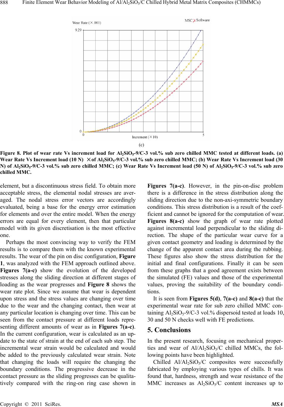
It is seen from wear analysis that as the load and dis-
persoid content increases the wear resistance of the
composite improves remarkably. SEM studies reveal that
wear surfaces of Al/Al2SiO5/C chilled composite at lower
loads showed slight groove formations than those of the
matrix alloy. At intermediate loads, damaged sections in
wear surfaces of the composites were seldom observed.
Consequently, the solid lubrication film formed as a re-
sult of adding carbon particulates improved the wear
resistance of Al/Al2SiO5/C hybrid composites. At higher
loads, localized melt and slip and large plastic deforma-
tions are the dominant factors contributing the removal
of the material. Comparison with experiments has con-
firmed the stability of the FE wear model developed, the
model provides a reasonable description and justification.
REFERENCES
[1] H. C. Yuen and W. B. Lee, “Hot bonding Al Matrix
Composite with Different Fraction of Alumina,” Material
Science, Vol. 30, 1995, pp. 843-849.
doi:10.1007/BF01178415
[2] H. C. Yuen, B. Ralph and W. B. Lee, “Novel Preparation
for an Aluminum-Alumina MMC by a Hot Roll Bonding
Process,” Scripta Metallurgica et Materialia, Vol. 29,
1993, pp. 695-670. doi:10.1016/0956-716X(93)90421-N
[3] B. Ralph, H. C. Yuen and W. B. Lee, “The Processing of
MMCs: An Overview,” Materials Processing Technology,
Vol. 63, 1997, pp. 1-8.
doi:10.1016/S0924-0136(96)02645-3
[4] Z. G. Wei, C. Y. Tang and W. B. Lee, “Design and Fab-
rication of Intelligent Composites Based on Shape,” Ma-
terials Processing Technology, Vol. 63, 1997, pp. 68-75.
doi:10.1016/S0924-0136(96)00041-6
[5] Y. P. Rao and W. B. Lee, “Processing a Particulate MMC
by Roll Bonding Method, Discussion Meeting on Inor-
ganic Matrix Composites,” Indian Institute of Science,
Bangalore, India, No. 3, 1995, pp. 8-18.
[6] K. Yeow, “Transaction Behavior of Unidirectional Rib-
bon Reinforced Metal Glass Epoxy Laminates,” Compos-
ite Materials, Vol. 14, 1980, pp. 132-139.
doi:10.1177/002199838001400110
[7] B. D. Agarwal and J. M. Lifshitz, “Elastic-Plastic Finite
Element Analysis of Short Fiber Composites,” Fiber Sci-
ence and Technology, Vol. 7, 1974, pp. 45-53.
doi:10.1016/0015-0568(74)90005-0
[8] T. G. Neigh and D. J. Chellman , “Modulus Measurements
in Discontinuous Reinforced Al Composites,” Scripta
Metallurgica, Vol. 18, 1984, pp. 925-931.
doi:10.1016/0036-9748(84)90262-X
[9] A. P. Divecha, S. G. Fishman and S. D. Karmarkar,
“Silicon Carbide Reinforced Al: A Formable Composite,”
Journal of Metals, Vol. 12, 1981, pp. 12-17.
[10] D. L. McDaniels, “Analysis of Stress-Strain, Fracture and
Ductility Behavior of Al MMCs Containing Discontinu-
ous Silicon Carbide Reinforcement,” Metallurgical
Transactions A, Vol. 16A, 1985, pp. 1105-1113.
doi:10.1007/BF02811679
[11] D. R. Williams and M. E. Fine, “Quantitative Determina-
tion of Fatigue Microcrack Growth in SiC Whisker Rein-
forced 2124 Al Alloy Composites,” Proceedings of
ICCM-V, San Diego, CA, AIME, TMS, Vol. 29, 1958, pp.
639-645.
[12] J. Hemanth, “Cryo Effect during Solidification on the
Tribological Behavior of Al-Alloy/Glass (SiO2) MMCs,”
Journal of Composite Materials, Sage publications, Vol.
43, 2009, pp. 675-688.
[13] J. Hemanth, “Tribological Behavior of Cryogenically
Treated Al-12%Si Alloy/B4C Composites,” Wear, El-
sevier Science, Vol. 258, 2005, pp. 1732-1745.
doi:10.1016/j.wear.2004.12.009
[14] J. Hemanth, “Cryogenic Effects during Solidification on
the Wear Behavior of Al Alloy/ Glass MMCs,” Journal of
Composite Materials Part A, Vol. 38, 2007, pp. 1395-
1402.
[15] J. Hemanth, “Development and Property Evaluation of
Al-Alloy Reinforced with Nano-ZrO2 Metal Matrix
Composites (NMMCs),” Journal of Materials Science
and Engineering A, Vol. 507, 2009, pp. 110-113.
doi:10.1016/j.msea.2008.11.039
[16] R. G. Schierding and O. D. Deex, “Factors Influencing
the Properties of Whisker-Metal Composites,” Composite
Materials, Vol. 3, 1969, pp. 618-625.
[17] T. T. Long, T. Nishimura and T. Aisaka, “Mechanical
Properties and Wear Resistance of 6061 Al Alloy Rein-
forced with Hybrid Fibers and Whiskers,” Transactions
of Japan Institute of Metals, Vol. 29, 1988, pp. 920-928.
[18] R. J. Arsenault, “The Strengthening of Al Alloy 6061 by
Fiber and Platelet SiC,” Materials Science and Engineer-
ing, Vol. 64, 1984, pp. 171-178.
doi:10.1016/0025-5416(84)90101-0
[19] S. V. Nair, J. K. Tien and R. C. Bates, “SiC Reinforced
Al MMCs” Institute of Metals, Vol. 30, 1985, pp. 275-
283.
[20] J. Hemanth, “Quartz (SiO2p) Reinforced Chilled Metal
Matrix Composites (CMMCs) for Automotive Applica-
tions,” Materials and Design, Elsevier Science, Vol. 30,
2009, pp. 323-329.
[21] J. Hemanth, “Development and Property Evaluation of
Al-Alloy Reinforced with Nano-ZrO2 Metal Matrix
Composites for Automotive Applications,” SAE Interna-
tional world congress, Paper No. 2009-01-0218, Detroit,
Michigan, USA, 2009.
[22] A. Razaghian, D. Yu and T. Chandra, “Fracture Behavior
of a SiC Particle Reinforced Al Alloy at High Tempera-
ture,” Composites Science and Technology, Vol. 58, 1998,
pp. 293-298. doi:10.1016/S0266-3538(97)00130-9
[23] S. Q. Wu, H. Z. Wang and S. C. Tjong, “Wear Behavior
Al Based Composites Reinforced with Ceramic Parti-
cles,” Compo sites Science an d Technology, Vol. 56, 1996,
Copyright © 2011 SciRes. MSA
Finite Element Wear Behavior Modeling of Al/Al2SiO5/C Chilled Hybrid Metal Matrix Composites (CHMMCs)
Copyright © 2011 SciRes. MSA
890
pp. 1261-1268. doi:10.1016/S0266-3538(96)00085-1
[24] S. C. Tjong, S. Q. Wu and H. C. Liao, “Wear Behavior of
Al-12%Si Alloy Reinforced with a Low Volume of SiC
Particles,” Composites Science and Technology, Vol. 57,
1997, pp. 1151-1158
[25] C. M. Friend, “The Effect of Alumina Fiber Array on the
Age Hardening Characteristics of and Al/Mg/Si Alloy,”
Materials Science, Vol. 22, 1987, pp. 3005-3012.
doi:10.1007/BF01086505
[26] J. M. Thompson, “A Proposal for the Wear Calculation,”
Department of Mechanical engineering, MIT, 2007, pp.
45-57.
[27] P. Podra and S. Anderson, “Simulating Sliding Wear with
Finite Element Method,” Tribology International, Vol. 32,
1999, pp. 71-81. doi:10.1016/S0301-679X(99)00012-2
[28] G. E. Lee, C. K. H. Dharan and R. O. Ritchie, “A physi-
cally Based Abrasive Wear Model for Composite Materi-
als,” Wear, Vol. 252, 2002, pp. 322-331.
doi:10.1016/S0043-1648(01)00896-1
[29] K. Elleuch and S. Fouvry, “Experimental and Modeling
Aspects of Abrasive Wear of a A357 Aluminum Alloy
under Gross Slip Fretting Conditions,” Wear, Vol. 258,
2005, pp. 40-49. doi:10.1016/j.wear.2004.04.010
[30] J. Hemanth, “Wear Characteristics of Sub Zero Chilled
Cast Iron,” Wear, Vol. 192, 1996, pp. 134-143.
doi:10.1016/0043-1648(95)06781-7
[31] J. Hemanth, “Effect of Cooling Rate on the Dendrite Arm
Spacing and Ultimate Tensile Strength of Cast Iron,”
Material Science, Vol. 33, 1998, pp. 23-35.
doi:10.1023/A:1004321007806
[32] J. Hemanth, “Effect of High Rate of Heat Transfer during
Solidification of Alloyed Cast Iron Using Water-Cooled
and Sub-Zero Chills on Mechanical Behavior,” Materials
and Design Vol. 24, 2003, pp. 37-45.
doi:10.1016/S0261-3069(02)00086-9
[33] J. F. Archard and W. Hirst, “The Wear of Metals under
Un-Lubricated Conditions,” Proceedings of the Royal So-
ciety-A, Mathematical, Physical and Engineering Sci-
ences, Vol. 236, 1956, pp. 397-410.
doi:10.1098/rspa.1956.0144
[34] J. J. Lewandowski, C. Liu and W. H. Hunt, “Microstruc-
ture Effects on the Fracture Micro-Mechanisms in Al
MMCs in Processing and Preparation for Powder Metal-
lurgy Composites,” P. Kumar and A. Ritter, Eds., TMS,
Vol. 12, 1988, pp. 117-128.
[35] M. Taya and R. J. Arsenault, “Heat Treating of Compos-
ite Materials,” Composite materials, Pergamon press, Vol.
35, 1989, pp. 56-67.
[36] B. Ralph, H. C. Yuen and W. B. Lee, “Mechanical Prop-
erties and Microstructure of Composite Materials,” Mate-
rials Processing Technology, Vol.63, 1997, pp. 9-18.
[37] V. G. Gorbounov and V. D. Parshin, “Sliding Wear
Characteristics of Al/SiO2 Composites,” Russian Casting
Production, Vol. 35, 1974, pp. 348-356
[38] T. G. Neigh, “Wear Regimes and Transition in Al2O3
MMCs,” Metallurgical and Materials Transactions, Vol.
15, 1984, pp. 139-146.
[39] P. K. Ghosh and S. K. Ray, Wear Behavior of Al-12%Si
Alloy Reinforced with Low Volume Fraction of SiO2
Particles,” Materials Science, Vol. 21, 1986, pp. 1167-
1175.
[40] E. Rabinowicz, “Friction Wear of Materials,” John Wiley
and Sons, New York, Vol. 32, 1965, pp. 168-177.
[41] J. F. Archard, “Properties of Composite Materials” Jour-
nal of Applied Physics, Vol. 24, 1953, pp. 981-988.
doi:10.1063/1.1721448
[42] A. G. Wang and I. M. Hutchings, “Wear of Alu-
mina-Fiber Aluminum Composites,” Materials Science
and Technology, Vol. 5, 1989, pp. 71-84.