 Journal of Biosciences and Medicines, 2016, 4, 51-56 Published Online March 2016 in SciRes. http://www.scirp.org/journal/jbm http://dx.doi.org/10.4236/jbm.2016.43009 How to cite this paper: Boonsiri, O., Washiya, K., Aoki, K. and Nagahashi, H. (2016) 3D Gray Level Co-Occurrence Matrix Based Classification of Favor Benign and Borderline Types in Follicular Neoplasm Images. Journal of Biosciences and Medi- cines, 4, 51-56. http://dx.doi.org/10.4236/jbm.2016.43009 3D Gray Level Co-Occurrence Matrix Based Classification of Favor Benign and Borderline Types in Follicular Neoplasm Images Oranit Boonsiri1*, Kiyotada Washiya2, Kota Aoki2, Hiroshi Nagahashi2 1Department of Computational Intelligence and Systems Science, Tokyo Institute of Technology, Tokyo, Japan 2Department of Imaging Science and Engineering Laboratory, Tokyo Institute of Technology, Tokyo, Japan Received 1 January 2016; accepted 10 March 2016; published 17 March 2016 Abstract Since the efficiency of treatment of thyroid disorder depends on the risk of malignancy, indeter- minate follicular neoplasm (FN) images should be classified. The diagnosis process has been done by visual interpretation of experienced pathologists. However, it is difficult to separate the favor benign from borderline types. Thus, this paper presents a classification approach based on 3D nuclei model to classify favor benign and borderline types of follicular thyroid adenoma (FTA) in cytological specimens. The proposed method utilized 3D gray level co-occurrence matrix (GLCM) and random forest classifier. It was applied to 22 data sets of FN images. Furthermore, the use of 3D GLCM was compared with 2D GLCM to evaluate the classification results. From experimental results, the proposed system achieved 95.45% of the classification. The use of 3D GLCM was better than 2D GLCM according to the accuracy of classification. Consequently, the proposed method probably helps a pathologist as a prescreening tool. Keywords Thyroid Follicular Lesion, 3D Gray Level Co-Occurrence Matrix, Random Ferest Classifier 1. Introduction Sub classification of FN has been proposed to triage each patient by considering the risk of malignancy for beneficial treatment. The Japan Thyroid Association (JTA) categorizes indeterminate FN into three levels of risk stratification [1]. First, the favor malignant type or high risk presents the high probability of malignancy around 40 - 60 percents. If a patient is identified as the favor malignant type by cytological diagnosis, the patient should imme diately receive its treatment. Furthermore, the borderline and the favor benign represent moderate and low risk, respectively. *Corresponding author.  O. Boonsiri et al. Due to the limitation of 2D microscope images, we can visualize cell images in one view point. In fact, cells are in different 3D locations, and they vary in size and shape. Thus, 3D image data may provide more significant information and advantages for analysis. Moreover, 3D image data may assist pathologists to explore more de- tails of a specific disease based on morphological properties and chromatin patterns in cancer cells. Thus, a computer aided diagnosis system based on 3D image is an additional option for pathologists to support clinical treatment. The availability of 3D imaging technologies would support pathologists and researchers to explore a new sig- nificant information of cell properties in 3D image. Currently, several researchers have investigated 3D micro- scopic images for 3D nuclei segmentation in fluorescence microscope images [2] [3] and bright field images [4]. In addition, 3D segmentation algorithms are based on watershed algorithm [5], gradient vector flow [2], and sliding band filter [4]. However, these methods are applied to clear background images. This study presents a classification approach for FN in volumetric data. The proposed method utilizes 3D GLCM algorithm to extract volumetric texture features. Then, these texture features are classified by a random forest classifier. The purpose of this classification is to discriminate between favor benign and borderline of FN in cytological specimens. The proposed method was applied to 22 data sets of FN 3D images. Furthermore, the comparison between 3D GLCM and 2DGLCM was examined to demonstrate an advantage of using 3D infor- mation. This paper is organized as follows. Section 2 describes details of the proposed method, and experimental re- sults are shown in Section 3. Finally, this study is concluded in Section 4. 2. Materials and Metho d s 2.1. 2D Nuclei Segmentation 2D nuclei segmentation is based on unsupervised learning. This study expects to detect all possible nuclei on each image. Referring to Figure 1, 2D nuclei segmentation contains two main steps. First, some parts of cytop- lasm and background areas are removed in a pre-processing step. In this step, the Otsu ’s binarization algorithm [6] and opening morphological operations are applied to each given 2D image slice. From the result, two cate- gories of segmented areas are presented as individual nuclei areas and compound areas. By considering the morphological properties of area and circularity, individual nuclei areas and compound areas can be identified. However, compound areas consist of nuclei and cytoplasm. Therefore, compound areas are required to process in the next step. In the second step, a pixel-based classification model is investigated for each data set. A random forest classifier [7] is utilized to classify nuclei areas and non-nuclei areas. We extract features of each pixel by utilizing RGB and HSV color spaces. Thus, each pixel is represented as a six-dimensional feature vector. In the training step, k-means clustering is applied to compound areas in each image slice for classifying them into N clusters. Afterward, all training features are labeled according to their nearest cluster center from the N clusters. However, cluster centers between training image slices may be closed to each other. In this case, clusters on dif- ferent slices are defined as a same cluster label. Moreover, each data set may obtain different numbers of labels to characterize the properties of data sets. Consequently, training features and their labels are applied to random forest classifier. Each testing pixel is represented by posterior probabilities of each label as a result of random forest. The label that provides maximum posterior probability is selected as a final label of the pixel. Further- more, if a cluster center of a labeled pixel in compound areas is near to cluster center of individual nuclei areas, this label will be identified as one of nuclear components. Figure 2(b) shows the result of 2D nuclei segmenta- tion. 2.2. 3D Cell Construction The overview of 3D nuclei construction process is described in Figure 3. First, we initialize the center slice k of an image stack as a reference slice for a target nucleus in 3D volumetric data. A target region in the reference slice k is defined by Rk, which is called a reference region. The next slice and previous slice from the reference image slice are given as m. Then, we divide the nucleus volume into top and bottom sections before applying the second and third steps to both sections. Thus, a neighbor slice is referred to an upper layer counted from the ref- erence image slice when the top section is considered. On the other hand, a neighbor image slice is a bottom layer. 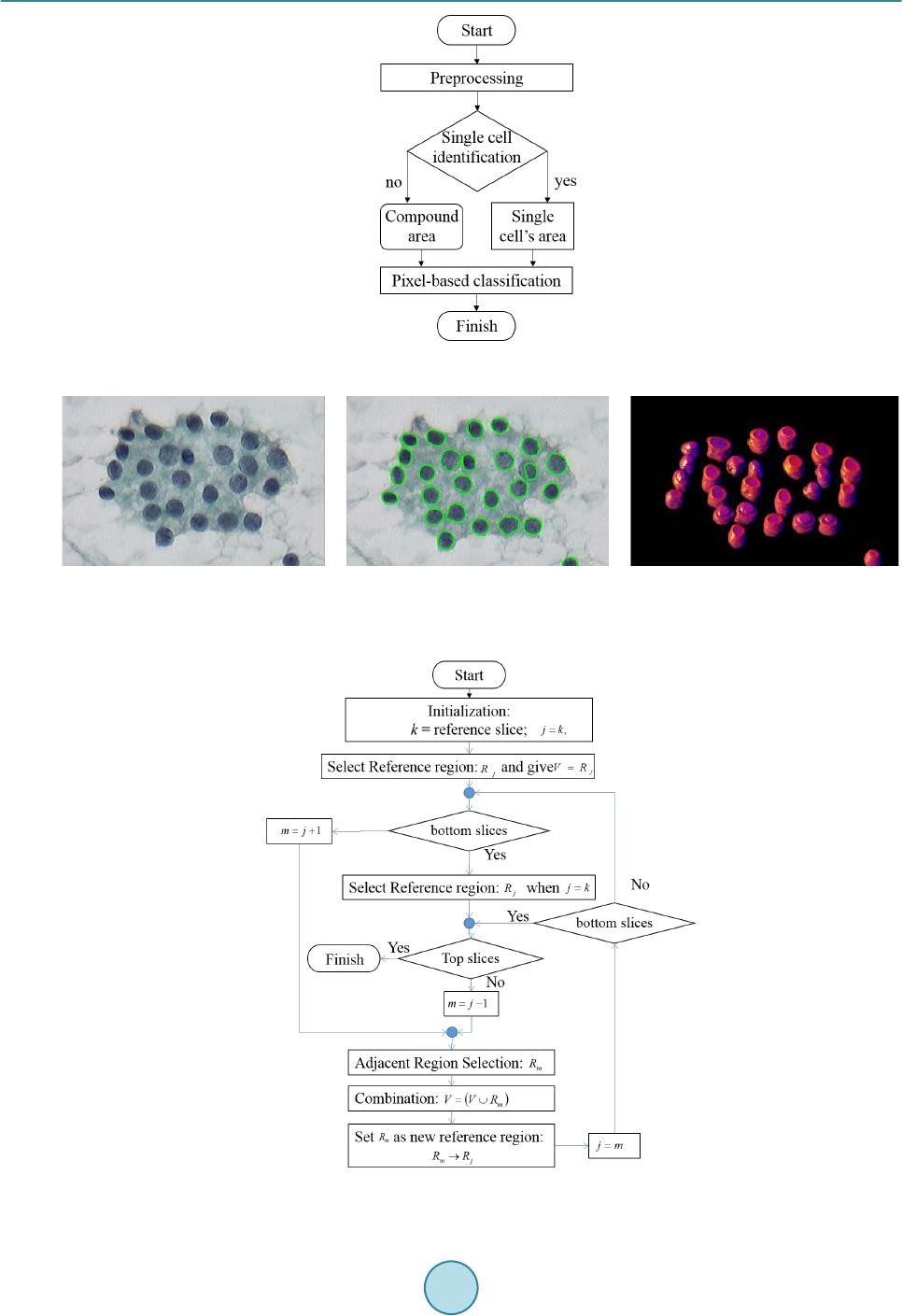 O. Boonsiri et al. Figure 1. A flow chart of the 2D nuclei segmentation. (a) (b) (c) Figure 2. Nu clei segmentation (a) An example of original image slice. (b) 2D nuclei segmentation result. (c) 3D nuclei mod- el. Figure 3. A flow chart for 3D nuclei construction.  O. Boonsiri et al. In the second step, the centroid of nuclear region is the key to discover nucleus in a neighbor image slice. In the case of both centroids of a nuclear region in a neighbor image slice and reference image slice are located at the similar position, they are probably located in the same nuclear volume. However, validation process is re- quired to confirm before merging them. The validation process is to analyze the following four cases. In the first case, if both nuclear sizes are similar, the considered area will be merged into the area at reference slice. For the second case, if a region in a neighbor image slice is smaller than the region in reference slice, the region in the neighbor image slice is replaced by the region in the reference slice. The third case is considered when a region in a neighbor image slice is larger than the reference image. In this case, the considered region will be classified as touching cell regions. Thus, we apply the watershed transform [8] to it for splitting the touching cell region. Next, one of split regions is combined with the region in the reference slice. In the final case, if no area appears in a neighbor image slice, a simulated region is generated based on the region in the ref- erence image and filled into the neighbor image slice for integrating with Rk. In the final step, a considered region in a neighbor image slice is labeled by the same number of Rk. Then, the considered region of the neighbor image slice is set as Rk for obtaining a new region in the next neighbor image slice. In addition, the second and the third main steps are iterated until the top and the bottom slices are found. The result of 3D nuclei model is shown in Figure 2(c). 2.3. 3D Gray Level Co-Occurrence Matrix For computation of 3D GLCM in three-dimensional image [9] [10], a co-occurrence matrix is a n × n matrix, where n is the number of gray levels in a given image. Basic concept of the computation is similar to a conven- tional 2D GLCM. A co-occurrence matrix collects the number of differences in intensities of two pixels indexed i and j in specific directions and distances. The co-occurrence matrix represents a displacement as d = (dx, dy, dz) where dx, dy and dz denote the number of pixel moved along x, y and z axis, respectively in volumetric data, re- spectively. Furthermore, displacement vectors contain 13-directions with offset D as shown in Table 1. Actually, direc- tion 1, 2, 3, and 4 are commonly used in 2D GLCM, and the additional nine directions are investigated in 3D GLCM. Next, haralick features [11] [12] is computed from the co-occurrence matrix to describe the texture of images. This study considers 12 statistical measurements including Energy, Entropy, Correlation, Contrast, Variance, Sum Mean, Inertia, Cluster Shade, Cluster Tendency, Homogeneity, Max Probability, and Inverse Variance. Table 1. Displacement vectors for co-occurrence matrix generation. ID D isp lacem ent vector Direction (horizontal, vertical) 1 (0, D, 0) (0˚, 0˚) 2 (−D, D, 0) (45˚, 0˚) 3 (−D, 0, 0) (90˚, 0˚) 4 (−D, −D, 0) (135 ˚, 0˚) 5 (0, D, −D) (0˚, 45˚) 6 (0, 0, −D) (none, 90˚) 7 (0, −D, −D) (0˚, 135˚) 8 (−D, 0, −D) (90˚, 45˚) 9 (D, 0, −D) (90˚, 135˚) 10 (−D, D, −D) (45˚, 45˚) 11 (D, −D, −D) (45˚, 135˚) 12 (−D, −D, −D) (135˚, 45˚) 13 (D, D, −D) (135˚, 135˚)  O. Boonsiri et al. Table 2. Comparison of classification accuracy between 2D GLCM and 3D GLCM . Textural feature Classification accuracy (%) 2D GLCM 90. 91 3D GLCM 95. 45 3. Experimental Result s 3.1. Image Acquisition The FTA datasets were captured by a virtual slide imager [Claro, optical: 1/2 type1.6 prism, effective pixels: 1360 (H) × 1024 (V)] with a 3CCD digital camera. This camera system focuses on the center of nuclei in cyto- logical specimens, and it automatically moves up and down along a depth direction with 0.25 μm for acquiring 3D image stacks. One stack contains 41 images with a 40x magnification of objective lens. 3.2. Implementation After completeing 3D nuclear segmentation as shown in Figure 2, the segmented nuclei were utilized to discri- minate favor benign and borderline in the classification step. In this experiment, 3D GLCM was applied to ex- tract chromatin patterns for each 3D nuclear model over 22 cases of FTA that contain 11 cases of favor benign and 11 cases of borderline. The total of 850 nuclei are examined. We set offset D = 1 in 13-directions. The 12 haralick features were extracted. Thus, we obtain 156 (13 × 12) dimensional feature vectors for each nucleus. After extracting feature descriptors, the classification procedure was performed by utilizing the random forest classifier. The final decision was made by majority voting strategy for each image stack. Furthermore, we eva- luated the performance by applying k-fold cross validation. The average accuracy over k-fold cross validation was obtained as a result of cross-validation accuracy. In addition, the use of 3D GLCM was compared to 2D GLCM by examining their performances of classification. 3.3. Classification Results The performance of classification was evaluated by using 10-fold cross validation as presented on Table 2. From the result, the use of the 3D GLCM descriptor successfully achieved 95.45% of classification rate whereas the classification based on the 2D GLCM descriptor was 90.91%. Thus, the use of 3D GLCM descriptor is better than the use of 2D GLCM to explore volumetric features for distinguishing favor benign and borderline in FTA. 4. Conclusion This paper presents a FTA classification system computed in volumetric data for classifying favor benign and borderline. We investigated the use of the 3D GLCM descriptor to extract volumetric texture features of chro- matin patterns inside a nucleus. Subsequently, the random forest classifier and majority voting strategy were performed to characterize favor benign and borderline. Moreover, experimental results showed that the use of the 3D GLCM descriptor achieved 95.45% of classification performance. However, a conventional 2D GLCM descriptor gave 90.91% of classification accuracy. Consequently, volumetric feature descriptors probably pro- vide more information of nuclear chromatin patterns for analysis. References [1] Kennichi, K., Kaori, K., Mitsuyoshi, H., Ryohei, K. and Hirotoshi, N. (2015) Subclassification of Follicular Neoplasms Recommended by the Japan Thyroid Association Reporting System of Thyroid Cytology. International Journal of Endocrinology, Article ID: 938305. [2] Kong, J., Wan g, F., Teodoro, G., Lia n g, Y., Zhu, Y., Tucker-Burden, C. and Brat, D. (2015 ) Automated Cell Segmen- tation with 3D Fluorescence Microscopy Images. IEEE 12th International Symposium on Biomedical Imaging (ISBI). http://dx.doi.org/10.1109/isbi.2015.7164091 [3] Indhumathi, C., Cai, Y., Gu a n, Y. and Opas, M. (20 11 ) An Automatic Segmentation Algorithm for 3D Cell Cluster Splitting Using Volumetric Confocal Images. Journal of Microscopy, 243, 60-76.  O. Boonsiri et al. http://dx.doi.org/10.1111/j.1365-2818.2010.03482.x [4] Quel has, P., Marcu zzo, M., M endo nça, A. M., Oliveira, M.J. and Campilho, A.C. (20 09) Cancer Cell Detection and Invasion Depth Estimation in Brightfield Images. BMVC. [5] St raka, M., Cruz, A. L. , Köchl, A., Šrámek, M., Fleisch mann, D. and Gröller, E. (2003) 3D Watershed Transform Combined with a Probabilistic Atlas for Medical Image Segmentation. Proceedings of MIT. [6] Otsu, N. (1979) A Threshold Selection Method from Gra y-Level Histograms. IEEE Transactions on Systems, Man and Cybernet ics, 9, 62-66. http://dx.doi.org/10.1109/TSMC.1979.4310076 [7] Brei man, L. (2001) Random Forests. Mach. Learn., 45, 5-32. http://dx.doi.org/10.1023/A:1010933404324 [8] Yan g, X., Li, H. and Zhou, X. (2006) {Nuclei Segmentation Using Marker-Controlled Watershed, Tracking Using Mean-Shift, and Kalman Filter in Time-Lapse Microscopy. Microscopy, 53, 2405-24 14 . http://dx.doi.org/10.1109/tcsi.2006.884469 [9] Kurani, A.S., Xu , D.H., Furst, J. and Raicu , D. S. (2004) Raicu. Co-Occurrence Matrices for Volumetric Data. 7th IASTED International Conference on Computer Graphics and Imaging, Kauai. [10] Tsai , F., Chang, C.-K., R au, J. -Y., Lin, T.-H. and Liu, G.-R. (20 07) 3D Computation of Gray Level Co-Occurrence in Hyperspectral Image Cubes. In: Yuille, A., Zhu, S., Cremers, D. and Wang, Y., Eds., Energy Minimization Methods in Computer Vision and Pattern Recognition, 4679, Springer, Berlin Heidelberg, 4 29-44 0. http://dx.doi.org/10.1007/978-3-540-741 98 -5_33 [11] Harali ck, R. (1979) Statistical and Structural Approaches to Text u re . Proceedings of the IEEE, 67, 786-804. http://dx.doi.org/10.1109/PROC.1979.11328 [12] Harali ck, R.M. and Shapiro, L.G. (1992) Computer and Robot Vision. Addison-Wesley Longman Publishing Co., Inc., Boston.
|