Paper Menu >>
Journal Menu >>
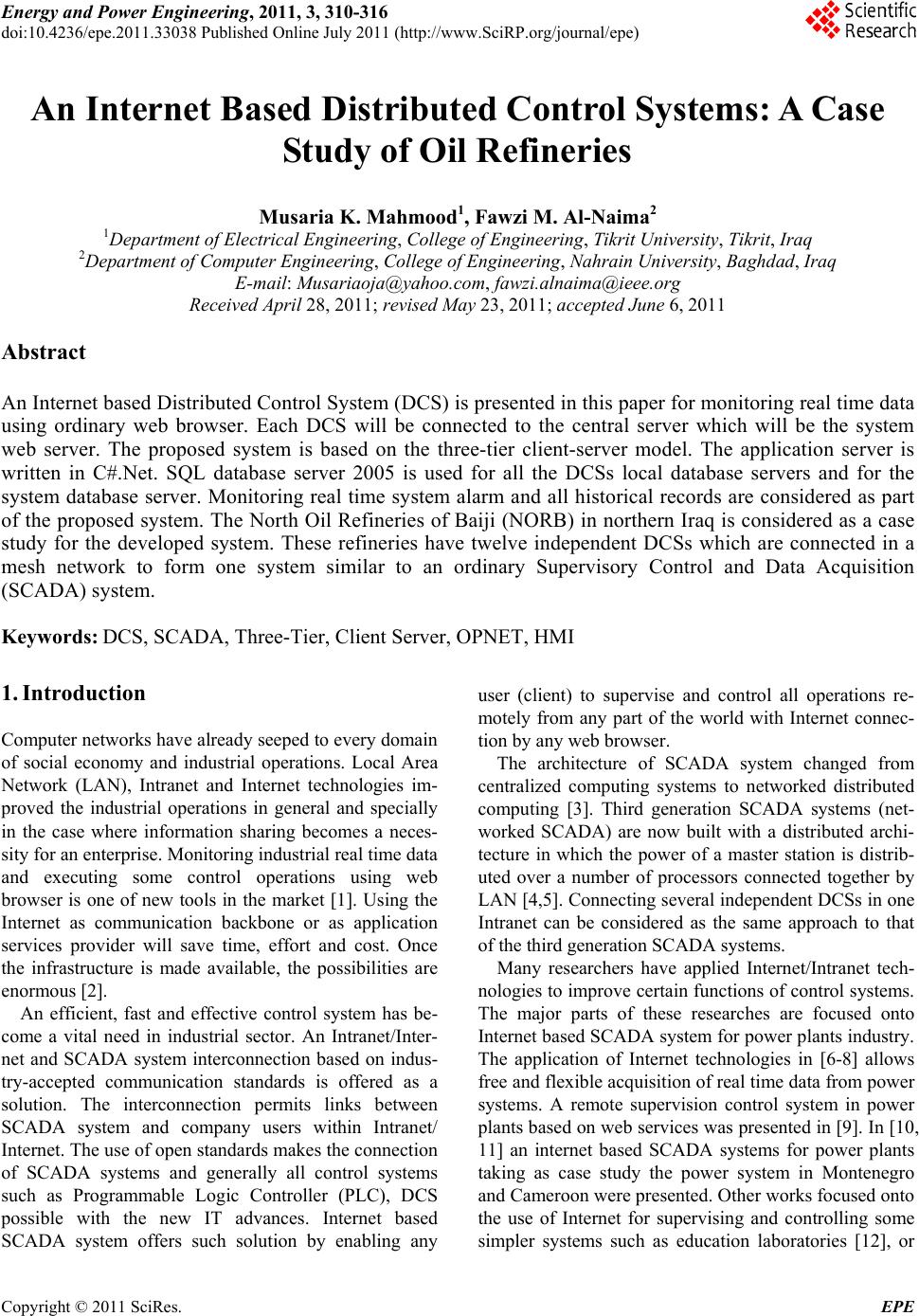 Energy and Power En gi neering, 2011, 3, 310-316 doi:10.4236/epe.2011.33038 Published Online July 2011 (http://www.SciRP.org/journal/epe) Copyright © 2011 SciRes. EPE An Internet Based Distributed Control Systems: A Case Study of Oil Refineries Musaria K. Mahmood1, Fawzi M. Al-Naima2 1Department of Electrical Engineering, College of Engineering, Tikrit University, Tikrit, Iraq 2Department of Computer Engineering, Col l ege of E ngineering, Nahrain University, Baghdad, Iraq E-mail: Musariaoja@yahoo.com, fawzi.alnaima@ieee.org Received April 28, 2011; revised May 23, 2011; accepted June 6, 2011 Abstract An Internet based Distributed Control System (DCS) is presented in this paper for monitoring real time data using ordinary web browser. Each DCS will be connected to the central server which will be the system web server. The proposed system is based on the three-tier client-server model. The application server is written in C#.Net. SQL database server 2005 is used for all the DCSs local database servers and for the system database server. Monitoring real time system alarm and all historical records are considered as part of the proposed system. The North Oil Refineries of Baiji (NORB) in northern Iraq is considered as a case study for the developed system. These refineries have twelve independent DCSs which are connected in a mesh network to form one system similar to an ordinary Supervisory Control and Data Acquisition (SCADA) system. Keywords: DCS, SCADA, Three-Tier, Client Server, OPNET, HMI 1. Introduction Computer networ ks have already seeped to every domain of social economy and industrial operations. Local Area Network (LAN), Intranet and Internet technologies im- proved the industrial operations in general and specially in the case where information sharing becomes a neces- sity for an enterprise. Monitoring industrial real time data and executing some control operations using web browser is one of new tools in the market [1]. Using the Internet as communication backbone or as application services provider will save time, effort and cost. Once the infrastructure is made available, the possibilities are enormou s [2 ]. An efficient, fast and effective control system has be- come a vital need in industrial sector. An Intranet/Inter- net and SCADA system interconnection based on indus- try-accepted communication standards is offered as a solution. The interconnection permits links between SCADA system and company users within Intranet/ Internet. The use of open standards makes the connection of SCADA systems and generally all control systems such as Programmable Logic Controller (PLC), DCS possible with the new IT advances. Internet based SCADA system offers such solution by enabling any user (client) to supervise and control all operations re- motely from any part of the world with Internet connec- tion by any web browser. The architecture of SCADA system changed from centralized computing systems to networked distributed computing [3]. Third generation SCADA systems (net- worked SCADA) are now built with a distributed archi- tecture in which the power of a master station is distrib- uted over a number of processors connected together by LAN [4,5]. Connecting several independent DCSs in one Intranet can be considered as the same approach to that of the third generation SCADA systems. Many researchers have applied Internet/Intranet tech- nologies to improve certain functions of control systems. The major parts of these researches are focused onto Internet based SCADA system for power plants industr y. The application of Internet technologies in [6-8] allows free and flexible acquisition of real time data from power systems. A remote supervision control system in power plants based on web services wa s presented in [9 ]. In [10 , 11] an internet based SCADA systems for power plants taking as case study the power system in Montenegro and Cameroon were presented. O ther wo rk s focused onto the use of Internet for supervising and controlling some simpler systems such as education laboratories [12], or  M. K. MAHMOOD ET AL.311 multi-units industrial facility [2]. An Internet based DCS usually deals with very com- plex systems of large number of control points in the field. In [13], three layers SCADA system was simulated where OPC service protocol is used to solve the com- patibility problem. An Internet based systems to allow monitoring of a DCS was presented in [14,15], while a method for managing DCS via company Intranet/Internet was considered in [16], and the design of remote real time supervisory system based on OPC was proposed in [1]. The NORB is a large industrial complex located on various sites scattered around the city of Baiji about 200km north of Baghdad. This complex comprises four large refineries: 1) Salah Aldine-1; 2) Salah Aldine-2; 3) North; and 4) Chemical Products. Also, six other refin- eries outside the region of Baiji form part of the same complex direction. Each refinery has many DCSs con- trolling several chemical processes. These processes are independent on each other and are installed at different geographical locations. Each DCS acts as standalone control system with its private communication network and Local Control Room (LCR). DCSs in operation are based on new information technology (IT) with open standards communication protocols such as TCP/IP pro- tocols using fiber optic Ethernet for data transmission between field and LCR. Connecting independent DCSs in the NORB in one system based on Intranet and connecting the system server located in the Central Con trol Room (CCR) to the Internet will be the principal part of the present research. 2. OPC-DCS Architecture The DCSs have long been employed in industrial fields to process real time data in chemical and other critical processes. DCSs are widely deployed in automatic con- trol and play increasingly vital roles in petroleum refin- eries. The dominating DCS products in Iraq refineries include Yamatake, Bradley, and Honeywell. All these systems are based on open standard with possibility to use TCP/IP communication protocols. A DCS is a com- plete system that includes closely integrated operator stations, control modules, and remote I/O (for interfacing analog and digital real world signals). The DCS is char- acterized by distributed intelligence in which each front-end controller is a microprocessor-based system. A central computer monitors and coordinates the entire network of intelligent controllers and devices. The inter- communication within the system is via digital commu- nication, and thus a DCS possesses all the benefits asso- ciated with digital transmission which include less cop- per costs, stronger immunity to noise, longer transmis- sion distance, higher reliability, and better re-configura- bility. Figure 1 shows a typical industrial architecture of a Yamatake DCS used in NORB. It is based on the use of DOPC which stands for Dependable OLE for Process Control, where OLE stands for Object Linking and Em- bedding developed in 1996 by the industrial automation industry. DOPC (DEO OPC) is a trademark of Yamatake OPC specifies the communication of real time plant data between control devices from different manufacturers. The OPC Specification was based on the OLE, Compo- nent Object Model (COM), and Distributed COM (DCOM) technologies developed by Microsoft for the Microsoft Windows operating system family. The DCSs from other vendors obey the same main blocks. DCS is based onto 10/100 Mbps optical fiber Ethernet used to interconnect all DCS parts. The data collected from fields is transferred to be projected into Dependable Open Supervisory Station (DOSS) as Local Control Room (LCR). A copy of real time data is stored into the DEO Open History Server (DOHS). DOHS can be con- sidered as local W eb server for external client [17]. 3. Client Server Multi-tier Complex control system such as SCADA, DCS, and PLC systems have evolved from mainframe based sys- tem to client-server architecture model. The clien t server architecture is more reliable system and very attractive model because it can be subject to network topological change. Client server architecture can be built using the two tier model where the first tier is the client and the DOFL Figure 1. OPC DCS architecture. Copyright © 2011 SciRes. EPE  M. K. MAHMOOD ET AL. 312 second tier is the server. The two tier client server model generally uses a database management system (DBMS) that provides the server and manages the client network connection both the client and the Server co-operate in executing the application, but the client contains all of the application logic as depicted in Figure 2. The server contains the DBMS which hides the complex functions that are needed to manage the data [18]. The three tier model introduces an additional element, or the middleware between the client and the server. The middleware runs on all machines that host a client or server. The task of the middleware is to provide services to clients or servers to en able efficient delivery of opera- tion requests and return of results. The middleware may typically provide other features, such as distributed sys- tem management facilities as shown in Figure 3. The flexibility and containment is provided in the middle layer of the three-tier architecture, allowing changes to be made relatively quickly and easily whilst they are at the same time localized in the middleware. This can be achieved with the minimum changes to the graphical user interface, or the database [19]. Internet based control system usually uses the three tier client server model as it is more practical for real time monitoring and con trol applications due to its flexi- bility and scalability [2 0]. 4. Development of an Internet Based DCS 4.1. Problem Definition and Modeling DCS is usually used to control co mplex industrial instal- lations with a large number of controlled points in the field. DCS has a distributed architecture with nodes (sa- Figure 2. Two-tier client server system. Figure 3. Three-tier client server system. tellites) acting as bridge between industrial fields and DOSS. As an example, one DCS of type Yamatake can support up to 60,000 tags (controlled points) distributed over 32 nodes as shown in Table 1. In the existing NORB only six distributed nodes are being used to col- lect information and co ntrol 2400 points in th e field [17]. Yamatake DCS uses Windows NT, and Windows 2000 or newer versions as operating system, SQL server 2000, 2005, or 2008 as DBMS, associated software packages for software platform and optical Ethernet solution for control/information network. DOHS Is the local historical server to collect plant data through the DOPC and store it in its file [17]. The developed system considers each DCS as Remote Ter- minal Unite (RTU) for a global SCADA system. Local server for each DCS (local DOHS), will be connected to the system server via Intranet/Internet. Real time data collected from the field of each DCS are stored in local DOHS and a copy is sent immediately to the system da- tabase server in the CCR. The depicted adopted model is shown in Figure 4. Due to the large collection of dev ices used in an oil re- finery, it is vital to use simple Human Machine Interface (HMI) to represent data by Internet browser. In this work C#.Net is used to build the middleware layer (server side) applets. The system server enables the function of glob- alization of infor mation of all DCSs through unique w eb Copyright © 2011 SciRes. EPE  M. K. MAHMOOD ET AL.313 Table 1. Yamatake system capacity. Tags supported 60,000 parameters/DOSS System-wide 126 nodes/network DOSS 32 nodes/NT cluster Total nodes DOPC/DOPL 96 nodes/NT cluster Local database server of DCS 1 DOHS 1 Local database server of DCS 2 DOHS 2 Local database server of DCS n DOHS n Figure 4. The adopted model of the network. server. The database system server is connected to the system web server and then to the internet. 4.2. Architecture Design 4.2.1. Datab as e Archi tecture The adopted system architecture is based on connecting all DOHS for all DCSs to the system database server. Data from different DCSs are grouped in the system da- tabase server as one SQL table for one DCS. Every DCS will have a data table with columns (field) representing collecting data (data from specific device) and new line is added for each updating period. New tables are gener- ated at midnight each day, while the old tables are classi- fied as historical database. From the official site of Mi- crosoft, it is recommended to use SQL server 2008 spe- cialized edition for web application as DBMS because tables with this type of DBMS are with unlimited field and lines. 4.2.2. Real Time Data Transmission Network System design must satisfy the requirement of real time data for critical process control system. Each node (satel- lite) can have maximum throughput of 19200 bps as specified for serial communication standard RS-232 used in the DOPC [17]. Keeping in mind the future extension each DCS will be considered as having 10-satellites, the DCS Bit Rate (BR) is then given by: BR = 19200 × 10=192000 bps = 24000 Byte/sec which is the maximum possible bit rate that can be up- loaded from one DCS in LCR to the system server in CCR. In order to validate the real time network design, the network in Figure 5 is simulated using OPNET modeler 14.5. FTP is the principal simulated protocol because it is responsible of uploading data from LCR to CCR. Other protocols are simulated which offer other services as database access, VoIP with PCM quality, and E-mail. The configuration of the simulation input is based on th e maximum possible BR of each DCS and that each refin- ery as having three DCSs. Links between nodes are of the same type with bandwidth of 44.736 Mbps point to point link from the archive of OPNET. The displayed graph shown in Figure 6 confirms that the communica- tion network is a real time network with maximum delay time not exceeding (0.4 sec). 4.3. Software Solution The developed Internet based control system uses C#.Net as programming platform. The main program resides in the web server side, so at the client side no programming requirement is needed. The program is built using many modules, and Figure 7 gives a simple flow chart of the Figure 5. Simulated network. Copyright © 2011 SciRes. EPE 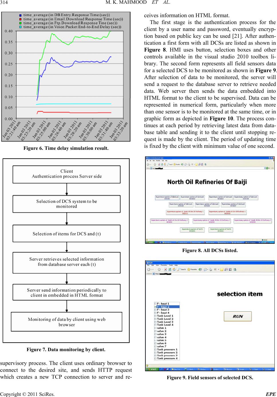 M. K. MAHMOOD ET AL. 314 Figure 6. Time delay simulation result. Figure 7. Data monitoring by client. supervisory process. The client uses ordinary browser to connect to the desired site, and sends HTTP request which creates a new TCP connection to server and re- ceives information on HTML format. The first stage is the authentication process for the client by a user name and password, eventually encryp- tion based on public key can be used [21]. After authen- tication a first form with all DCSs are listed as shown in Figure 8. HMI uses button, selection boxes and other controls available in the visual studio 2010 toolbox li- brary. The second form represents all field sensors data for a selected DCS to be monitored as shown in Figure 9. After selection of data to be monitored, the server will send a request to the database server to retrieve needed data. Web server then sends the data embedded into HTML format to the client to be supervised. Data can be represented in numerical form, particularly when more than one sensor is to b e monitored at th e same time, or in graphic form as depicted in Figure 10. The process con- tinues at each period by retrieving latest data from data- base table and sending it to the client until stopping re- quest is made by the client. The period of updating time is fixed by the client with minimum value of one second. Figure 8. All DCSs listed. Figure 9. Field sensors of selected DCS. Copyright © 2011 SciRes. EPE 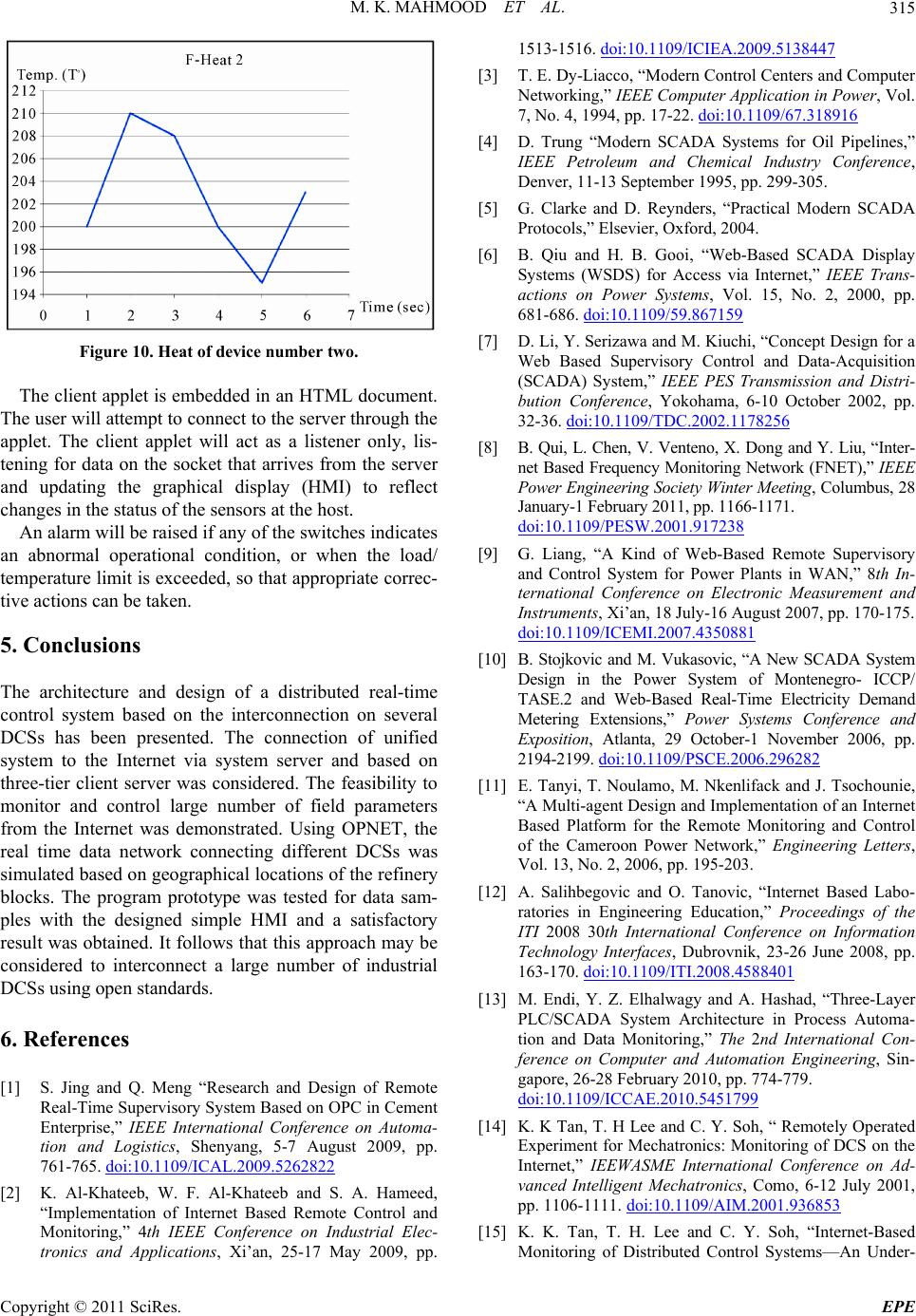 M. K. MAHMOOD ET AL.315 Figure 10. Heat of device number two. The client applet is embedded in an HTML document. The user will attempt to connect to th e server thro ugh the applet. The client applet will act as a listener only, lis- tening for data on the socket that arrives from the server and updating the graphical display (HMI) to reflect changes in the status of the sensors at the host. An alarm will be raised if any of the switches indicates an abnormal operational condition, or when the load/ temperature limit is exceeded, so that appropriate correc- tive actions can be taken. 5. Conclusions The architecture and design of a distributed real-time control system based on the interconnection on several DCSs has been presented. The connection of unified system to the Internet via system server and based on three-tier client server was considered. The feasibility to monitor and control large number of field parameters from the Internet was demonstrated. Using OPNET, the real time data network connecting different DCSs was simulated based on geographical locations of the refinery blocks. The program prototype was tested for data sam- ples with the designed simple HMI and a satisfactory result was obtained. It follows that this app roach may be considered to interconnect a large number of industrial DCSs using o pen standards. 6. References [1] S. Jing and Q. Meng “Research and Design of Remote Real-Time Supervisory System Based on OPC in Cement Enterprise,” IEEE International Conference on Automa- tion and Logistics, Shenyang, 5-7 August 2009, pp. 761-765. doi:10.1109/ICAL.2009.5262822 [2] K. Al-Khateeb, W. F. Al-Khateeb and S. A. Hameed, “Implementation of Internet Based Remote Control and Monitoring,” 4th IEEE Conference on Industrial Elec- tronics and Applications, Xi’an, 25-17 May 2009, pp. 1513-1516. doi:10.1109/ICIEA.2009.5138447 [3] T. E. Dy-Liacco, “Modern Control Centers and Computer Networking,” IEEE Computer Application in Power, Vol. 7, No. 4, 1994, pp. 17-22. doi:10.1109/67.318916 [4] D. Trung “Modern SCADA Systems for Oil Pipelines,” IEEE Petroleum and Chemical Industry Conference, Denver, 11-13 September 1995, pp. 299-305. [5] G. Clarke and D. Reynders, “Practical Modern SCADA Protocols,” Elsevier, Oxford, 2004. [6] B. Qiu and H. B. Gooi, “Web-Based SCADA Display Systems (WSDS) for Access via Internet,” IEEE Trans- actions on Power Systems, Vol. 15, No. 2, 2000, pp. 681-686. doi:10.1109/59.867159 [7] D. Li, Y. Serizawa and M. Kiuchi, “Concept Design for a Web Based Supervisory Control and Data-Acquisition (SCADA) System,” IEEE PES Transmission and Distri- bution Conference, Yokohama, 6-10 October 2002, pp. 32-36. doi:10.1109/TDC.2002.1178256 [8] B. Qui, L. Chen, V. Venteno, X. Dong and Y. Liu, “Inter- net Based Frequency Monitoring Network (FNET),” IEEE Power Engineering Society Winter Meeting, Colu mbus, 28 January-1 February 2011, pp. 1166-1171. doi:10.1109/PESW.2001.917238 [9] G. Liang, “A Kind of Web-Based Remote Supervisory and Control System for Power Plants in WAN,” 8th In- ternational Conference on Electronic Measurement and Instruments, Xi’an, 18 July-16 August 2007, pp. 170-175. doi:10.1109/ICEMI.2007.4350881 [10] B. Stojkovic and M. Vukasovic, “A New SCADA System Design in the Power System of Montenegro- ICCP/ TASE.2 and Web-Based Real-Time Electricity Demand Metering Extensions,” Power Systems Conference and Exposition, Atlanta, 29 October-1 November 2006, pp. 2194-2199. doi:10.1109/PSCE.2006.296282 [11] E. Tanyi, T. Noulamo, M. Nkenlifack and J. Tsochounie, “A Multi-agent Design and Implementation of an Internet Based Platform for the Remote Monitoring and Control of the Cameroon Power Network,” Engineering Letters, Vol. 13, No. 2, 2006, pp. 195-203. [12] A. Salihbegovic and O. Tanovic, “Internet Based Labo- ratories in Engineering Education,” Proceedings of the ITI 2008 30th International Conference on Information Technology Interfaces, Dubrovnik, 23-26 June 2008, pp. 163-170. doi:10.1109/ITI.2008.4588401 [13] M. Endi, Y. Z. Elhalwagy and A. Hashad, “Three-Layer PLC/SCADA System Architecture in Process Automa- tion and Data Monitoring,” The 2nd International Con- ference on Computer and Automation Engineering, Sin- gapore, 26-28 February 2010, pp. 774-779. doi:10.1109/ICCAE.2010.5451799 [14] K. K Tan, T. H Lee and C. Y. Soh, “ Remotely Operated Experiment for Mechatronics: Monitoring of DCS on the Internet,” IEEWASME International Conference on Ad- vanced Intelligent Mechatronics, Como, 6-12 July 2001, pp. 1106-1111. doi:10.1109/AIM.2001.936853 [15] K. K. Tan, T. H. Lee and C. Y. Soh, “Internet-Based Monitoring of Distributed Control Systems—An Under- Copyright © 2011 SciRes. EPE 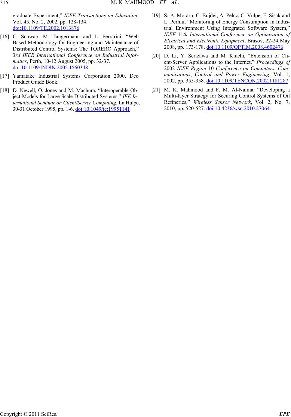 M. K. MAHMOOD ET AL. Copyright © 2011 SciRes. EPE 316 graduate Experiment,” IEEE Transactions on Education, Vol. 45, No. 2, 2002, pp. 128-134. doi:10.1109/TE.2002.1013876 [16] C. Schwab, M. Tangermann and L. Ferrarini, “Web Based Methodology for Engineering and Maintenance of Distributed Control Systems: The TORERO Approach,” 3rd IEEE International Conference on Industrial Infor- matics, Perth, 10-12 August 2005, pp. 32-37. doi:10.1109/INDIN.2005.1560348 [17] Yamatake Industrial Systems Corporation 2000, Deo Product Guide Book. [18] D. Newell, O. Jones and M. Machura, “Interoperable Ob- ject Models for Large Scale Distributed Systems,” IEE In- ternational Seminar on Client/Server Computing, La Hulpe, 30-31 October 1995, pp. 1-6. doi:10.1049/ic:19951141 [19] S.-A. Moraru, C. Bujdei, A. Pelcz, C. Vulpe, F. Sisak and L. Perniu, “Monitoring of Energy Consumption in Indus- trial Environment Using Integrated Software System,” IEEE 11th International Conference on Optimization of Electrical and Electronic Equipment, Brasov, 22-24 May 2008, pp. 173-178. doi:10.1109/OPTIM.2008.4602476 [20] D. Li, Y. Serizawa and M. Kiuchi, “Extension of Cli- ent-Server Applications to the Internet,” Proceedings of 2002 IEEE Region 10 Conference on Computers, Com- munications, Control and Power Engineering, Vol. 1, 2002, pp. 355-358. doi:10.1109/TENCON.2002.1181287 [21] M. K. Mahmood and F. M. Al-Naima, “Developing a Multi-layer Strategy for Securing Control Systems of Oil Refineries,” Wireless Sensor Network, Vol. 2, No. 7, 2010, pp. 520-527. doi:10.4236/wsn.2010.27064 |