Paper Menu >>
Journal Menu >>
 Energy and Power En gi neering, 2011, 3, 299-309 doi:10.4236/epe.2011.33037 Published Online July 2011 (http://www.SciRP.org/journal/epe) Copyright © 2011 SciRes. EPE Monitoring and Controlling Services for Electrical Distribution Systems Based on the IEC 61850 Standard* Rodrigo Prat, Gustavo Rodriguez, Fernando Magnago Facultad de Ingeniería, Universidad Nacional de Río Cuarto, Río Cuarto, Argentina E-mail: fmagnago@ing.unrc.edu.ar Received April 18, 2011; revised April 30, 2011; accepted May 10, 2011 Abstract International standards are being developed to promote rapid configuration and integration into the utility automation system. In order to take advantage of modern technology to provide new benefits to users of sub- station automation, the International Electrotechnical Commission (IEC) has developed and released a new global standard for substation automation, named IEC 61850. This aim of this paper is to provide a basic technical overview of substation automation and the standard IEC 61850. It will discuss the benefits of each major aspect of this standard and it will describe how these concepts can be used in the development and im- plementation of tools related to Substation Automation. The application of communication standards and protocols to facilitate data exchange within the substation environment is presented. In addition, the model is implemented using a small distribution system that plans to utilize new communication technology following the IEC 61850 standard. Finally it proposes a set of laboratories to be used as the core of an undergraduate course. Results illustrate that the communication approach as proposed by IEC 61850 fulfills the real-time requirements for control and protection of distribution system. Keywords: Substation Automation, IEC 61850 1. Introduction The main function of electric power systems (EPS) is to produce, transmit and deliver energy to the users. Within this field there are important issues that need to be con- sidered which cause many undesirable effects such as service interruptions and outages produced by equipment failures, natural storms or accidents. Although to miti- gate these effects have always been important, this im- portance has increased recently due to the evolution of the demand that requires uninterrupted and high quality of electric power. Therefore, the challenge for the EPS is to provide a quick response to the undesirable effects, maintaining reliability and competitive prices. Within this scenario, having high quality real time information becomes a very important concern. One way to improve this is through fully integrated, automated and remotely supervised sys- tems that require minimal human interven tion [1]. Consequently, automation of power distribution sys- tems has increasingly been adopted by power utilities worldwide in recent years as part of their efforts to pro- vide a more reliable supply to its customers and to en- hance operational efficiency. Thus, the principal objec- tive of electric system automation is to respond rapidly to real time events with pre-specified actions in order to maintain uninterrup ted power service [2]. Although the systems already use automation, nowa- days an additional subject is becoming important: the growing share of disperse and renewable generation. Therefore the traditional assumption that the electricity flow direction goes unidirectional from higher to lower voltage levels does not stand any longer. The increasing penetration of distributed generation into the system re- sults on bidirectional power flow and, as a consequence, the architecture and technology used for system automa- tion need to address this new system structure [3]. Hence, electric system automation infrastructure needs to increase the level of intelligence and integration of information and communication technologies (ICT). Current efforts related to the innovation and the devel- opment of this topic is known as Smart Grid [4]. The Smart Grid vision of electrical system, remarks the im- portance and benefits of communications to deliver real time information and enables the near instantaneous bal- *This work was supported by CONICET (Argentina).  R. PRAT ET AL. 300 ance supply and demand at device level [5]. Under these circumstances, standardization plays a crucial role in building up an intelligent power system grid. Many researchers and several international organiza- tions are currently developing the required communica- tion technologies and the international communication standards for electric system automation [6]. In addition, as the understanding of these topics be- comes very important for power engineers, the incorpo- ration of practical experiences on this matter in the un- dergraduate curricula is fundamental [7], together with the design of new laboratories to expose students to real life situations within this area. This paper discusses the state of the art of communi- cation standards and protocols to facilitate data exchang e within the substation environment and proposes a set of educational laboratories to expose undergraduate stu- dents to this technology. First, it remarks the advantages of substation automation; second, it describes the evolu- tion of substation communication, gives an introduction to Intelligent Electronic Devices (IED) and their impact on the substation communication architecture, and then, provides a basic technical overview of IEC 61850, where its main features are highlighted. Besides, the paper dis- cusses the benefits of each major aspect of the standard, and describes how they can be used in the development and implementation of systems for different substation level applications. Finally, an implementation of moni- toring and controlling services for electrical distribution systems employing the IEC 61850 standard is presented. This implementation is designed as a set of laboratories to be implemented into the undergraduate curricula. 2. Substation Automation Systems The principal function of the Substation Automation System (SAS) is to provide SCADA RTU (Remote Ter- minal Unit) functionality. The initial function was to concentrate data from the substation into one or more messages for transmitting them to the master station [8]. Nowadays, the Substation Automation System (SAS) also comprises protection as well as control, monitoring, and communication functions that furnishes all functions required for the safe and reliable operation of the sub sta- tion. It allows operating substations based on accurate information provided in a timely manner to the decision making application and devices. Moreover, it incorpo- rates several advantages to the management of the dis- tribution systems. These advantages are presented in different areas: operation, customer services, and finan- cial performance. From all the advantages the following can be high- lighted: Enhanced operational efficiency. Improved communication. Better-quality customer services. Improve d fi nancial pe rformance. Maximized incentives. Although the concept of SAS is not new, it becomes popular now due to the current needs and the evolution of communication technologies. Initially the SAS archi- tecture made use of a master-slave architecture in a star topology and used vendor specific proprietary protocols. Among the limitations, it can be remarked that the user was bound to one vendor, there was no direct communi- cation between slaves and the master communication represented a bottleneck. In 2002 Ethernet became available for speeds up to 10 Gbps which provides standardized high speed commu- nication. Furthermore, the introduction of distributed functionalities replaced the master-slave structure and the development of enhanced and comprehensive secu- rity, made SAS architecture to improve drastically [1]. In addition, electronic dev ices technology improved as well. The development of Intelligent Electron ic Devices (IED) typically consists of one or more microprocessors and communication ports with the ability to transmit d ata and execute control commands, which makes further devel- opment for SAS architectures possible. 3. Intelligent Electronic Devices Advances in digital electronics and communication technology have enabled improvements on RTUs and become Internet-ready Intelligent Electronic Devices. The main functions of a typical IED include protection, control, monitoring, metering and communications. Inte- grating these IEDs into electric systems can offer several benefits, among others, remote access to the relay con- figuration ports, diagnostic event information, and video for security or equipment status assessment. Nowadays, in SAS, the accurate functionality of a system depends on the integrity and the interoperability of IEDs from different manufacturers. The key objectives for designing the substation auto mation architecture are the interopera- bility between IEDs, the satisfaction of communication performance, and the extens ibility of the architecture. As we move into the digital age, literally thousands of analog and digital data points are available in a single IED, being communication bandwidth no longer a limit- ing factor. The evolution of the technology developments within this area are explained next. Copyright © 2011 SciRes. EPE  R. PRAT ET AL.301 4. Evolution of Substation Communication Until 1985 there were no standards, few vendors pro vide basic devices for substation, interoperability was not considered and all systems were proprietary. These first devices did not use the same physical in- terfaces or protocols, even the same vendors developed devices with communication protocols that were incom- patible. The network architecture was employed a mas- ter-slave network topology and communication between substations was not possible. The communication meth- ods were based on RS232, RS485, phone line, radio, and high voltage transmission lines. The speed was up to 1200 bits per second, and the used protocols were Mod- bus, SEL, WISP, or Conitel 2020. Initially, the communication systems applied for SAS were proprietary; therefore interconnection between de- vices from different vendors, which were few, was very difficult. From 1985 to 1990 more vendors provide devices for Substation Automation, some protocol converters allow basic interoperability among different devices and the use of microprocessor decentralized architecture make redundancy and multiple masters possible. New ad- vances on technology permit the communication speed to increase up to 19200 bps. The most popular protocols were DNP3 and the first version of IEC 870. From 1990 the need for standardization and the evolu- tion of the technology change this scenario. Developing of interoperability from physical (connectors, voltage levels) to communication protocols becomes an impor- tant issue. Local Area Network (LAN) was introduced in substa- tion applications, different substations were able to be communicated using Wide Area Networks (WAN). The technology applied was Frame Relay, ATM, and Ether- net, and communication speed increases over 1 Mbps. Protocols like Transport Control Protocol/Internet Pro- tocol (TCP/IP), Hypertext Transfer Protocol (HTTP) and File Transfer Protocol (FTP) started to be used within the stations. Several protocols were adapted to work on TCP/IP like Modbus, DNP3, IEC 60870 and initial work on standardization started. The development of standards started in 1994 when EPRI started a project named UCA (Utility Communica- tion Architecture). Based on the requirements, the com- pilation of different existing international standards in data networks and computer communication was done [9,10]. In 1996 the IEC Technical Committee 57 started a similar standardization project named IEC 61850 [5], then, in 1997 both groups joined to define a single stan- dardization under the name IEC 61850. As a result of these agreements, in 2004, a new version of the standard was released [11]. Finally in 2009, the standard incorpo- rated the Distributed Energy Resources (DER) [12]. The main features of this standard are described in the fol- lowing section. 5. Features of the Standard IEC 61850 International standards are being developed to promote rapid configuration and integration into the utility auto- mation system [19]. The IEC 61850 presents the in terna- tional standard for communication networks and system in substation automation The approach of the standard IEC 61850 is founded on the separation of the object model with its data and ser- vices from the communication. This allows both to fol- low the state-of-the-art communication technology (stack) and to safeguard the investments in functions and data- bases (object model). Therefore, the standard is fu- ture-proof as far as possible. Among its main features, the following can be highlighted: Interoperability by various manufacturers IEDs as an integrated system; High data transfer among IEDs considering peer to peer communication model instead of master-slave communication model in recent protocols; Data definition based on advanced object-oriented model which contains whole data specifications in- stead of single-oriented model with each data defini- tion by numeric addresses; Supporting functionality of devices to provide better communication; Communications extend ability and data integrity; Providing integrated communication system; Providing robust management of substation automa- tion system. Three important aspects are considered in the norm: a comprehensive data model (Object model), the commu- nication service to access and exchange data, and the Substation Configuration Language (SCL). 5.1. Object Models The data modeling of the IEDs are defined following an object oriented modeling. One of the main objectives of the norm is to establish the interoperability among de- vices from different vendors, therefore the communica- tion and interaction is based on an abstract communica- tion architecture that provides a hierarchic class set with associated services which are protocol independent. The norm defines a service model, named Abstract Commu- nication Service Interface (ACSI), which is used for data Copyright © 2011 SciRes. EPE  R. PRAT ET AL. 302 and service definition. The IED ACSI models in a hierarchic order are: Server: represents what can be seen from a device, all other models are part of the server; Logical Device (LD): contains the information pro- duced by a group of functions of specific applications. Functions are defined as logical nodes; Logical Node (LN): contains the information pro- duced by a specific functi o n; Data: provides the tools to define the type of informa- tion included in a LN. These basic ACSI information models are illustrated in Figure 1. Based on these models, a client application under IEC 61850 is able to know the complete str ucture of the IED, or the portion that is allowed to use. This information can be obtained in a recursive manner and built on a hierar- chical structure using the associated services, among which the most important are GetServerDirectory, Get- LogicalDeviceDirectory, GetLogicalNodeDirectory, Get AllDataValues, GetDataValue and SetDataValue. These services are mapped into specific application and communication protocols are defined in the norm by a Specific Communication Service Mapping (SCSM). 5.2. Communication 5.2.1. Communication Lev el s From the communication point of view, SAS can be con- sidered divided into three different levels: Process level: the lowest level which includes sensors, current and voltage transformers, circuit breakers, and any devices needed for the monitor and operation of the substation; Figure 1. ACSI information models hierarchical structure. Bay level: includes control and protection devices, can also include functions related with the operation of other bays; Substation level: it is the highest level; it includes local consol central units (gateways) that are con- nected to the control center. 5.2.2. Protoc ol Stacks The norm defines the use of different protocols depend- ing on the transmitted message type. The sample values, GOOSE messages and the GSSE are directly mapped onto the data layers; therefore, these types of messages can not be directed to another network. Simple Network Time Protocol is used to synchronize messages. The Ab- stract Communication Service Interface is mapped onto the Manufacturing Message Specification layer [9]. These different layers are shown in Figure 2. 5.3. Substation Configuration Language (SCL) This language is a formal way to describe how individual devices are configured; that is, what data and services they are supposed to be supporting. This language is an XML based language, following a W3C XML Schema. Four file types which describe the automation requirements and devices are defined. These files are: IED Capability Description file, extension ICD, describes the IED capacity. Configured IED Description, extension CID, describes the IED configuration for a specific project. System Specification Description, ex- tension SSD, describes the substation and logical nodes required. Substation Configuration Description, exten- sion SCD, describes the communication, all IEDs used, and the substation. The norm establishes the files struc- tures which contains a header, a substation description, the IEDs configuration, the communication system, and the data type. These data are mandatory or optional de- pending on the file typ e as illustrated in Table 1. Figure 2. IEC 61850 communication protocols profile. Copyright © 2011 SciRes. EPE 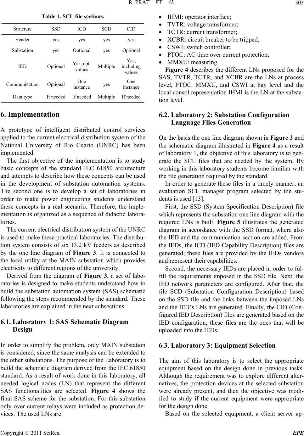 R. PRAT ET AL.303 Table 1. SCL file sections. Structure SSD ICD SCD CID Header yes yes yes yes Substation yes Optional yes Optional IED Optional Yes, opt. values Multiple Yes, including values Communication Optional One instance yes One instance Data type If needed If needed Multiple If needed 6. Implementation A prototype of intelligent distributed control services applied to the current electrical distribu tion system of the National University of Rio Cuarto (UNRC) has been implemented. The first objective of the implementation is to study basic concepts of the standard IEC 61850 architecture and attempts to describe how these concepts can be used in the development of substation automation systems. The second one is to develop a set of laboratories in order to make power engineering students understand these concepts in a real scenario. Therefore, the imple- mentation is organized as a sequence of didactic labora- tories. The current electrical distribution system of the UNRC is used to make these practical laboratories. The distribu - tion system consists of six 13.2 kV feeders as described by the one line diagram of Figure 3. It is connected to the local utility at the MAIN substation which provides electricity to different regions of the university. Derived from the diagram of Figure 3, a set of labo- ratories is designed to make students understand how to build the substation automation system (SAS) schematic following the steps recommended by the standard. These laboratories are explained in the next subsections. 6.1. Laboratory 1: SAS Schematic Diagram Design In order to simplify the problem, only MAIN substation is considered, since the same analysis can be extended to the other substations. The purpose of the Laboratory is to build the schematic diagram derived from the IEC 61850 standard. As a result of work done in this laboratory, all needed logical nodes (LN) that represent the different SAS functionalities are selected. Figure 4 shows the final SAS scheme for the substation. For this substation only over current relays were included as protection de- vices. The used LNs are: IHMI: operator interface; TVTR: voltage transformer; TCTR: current transformer; XCBR: circuit breaker to be tripped; CSWI: switch controller; PTOC: AC time over current protection; MMXU: measuring. Figure 4 describes the different LNs proposed for the SAS, TVTR, TCTR, and XCBR are the LNs at process level, PTOC. MMXU, and CSWI at bay level and the local consol represen tation IHMI is the LN at the substa- tion level. 6.2. Laboratory 2: Substation Configuration Language Files Generation On the basis the one line diagram shown in Figure 3 and the schematic diagram illustrated in Figure 4 as a result of laboratory 1, the objective of this laboratory is to gen- erate the SCL files that are needed by the system. By working in this laboratory students become familiar with the file generat i on required by the sta ndard. In order to generate these files in a timely manner, an evaluation SCL manager program selected by the stu- dents is used [13]. First, the SSD (System Specification Description) file which represents the substation one line d iagram with the required LNs is built. Figure 5 illustrates the generated diagram in accordance with the SSD format, where also the IED and the communication section are added. From the IEDs, the ICD (IED Capability Description) files are generated; these files are provided by the IEDs vendors and represent their capabilities. Second, the necessary IEDs are placed in order to ful- fill the requirements imposed in the SSD file. Next, the IED network parameters are configured. After that, the file SCD (Substation Configuration Description) based on the SSD file and the links between the imposed LNs and the IED’s LNs are generated. Finally, the CID (Con- figured IED Description) files are generated based on the IED configuration, these files are the ones that will be uploaded into the IEDs. 6.3. Laboratory 3: Equipment Selection The aim of this laboratory is to select the appropriate equipment based on the design done in previous tasks. Although the requirement was to explore different alter- natives, the protection devices at the selected substation were already present, and then the objective was modi- fied to study if the current equipment were appropriate for the design done. Based on the selected equipment, a client server ap- Copyright © 2011 SciRes. EPE 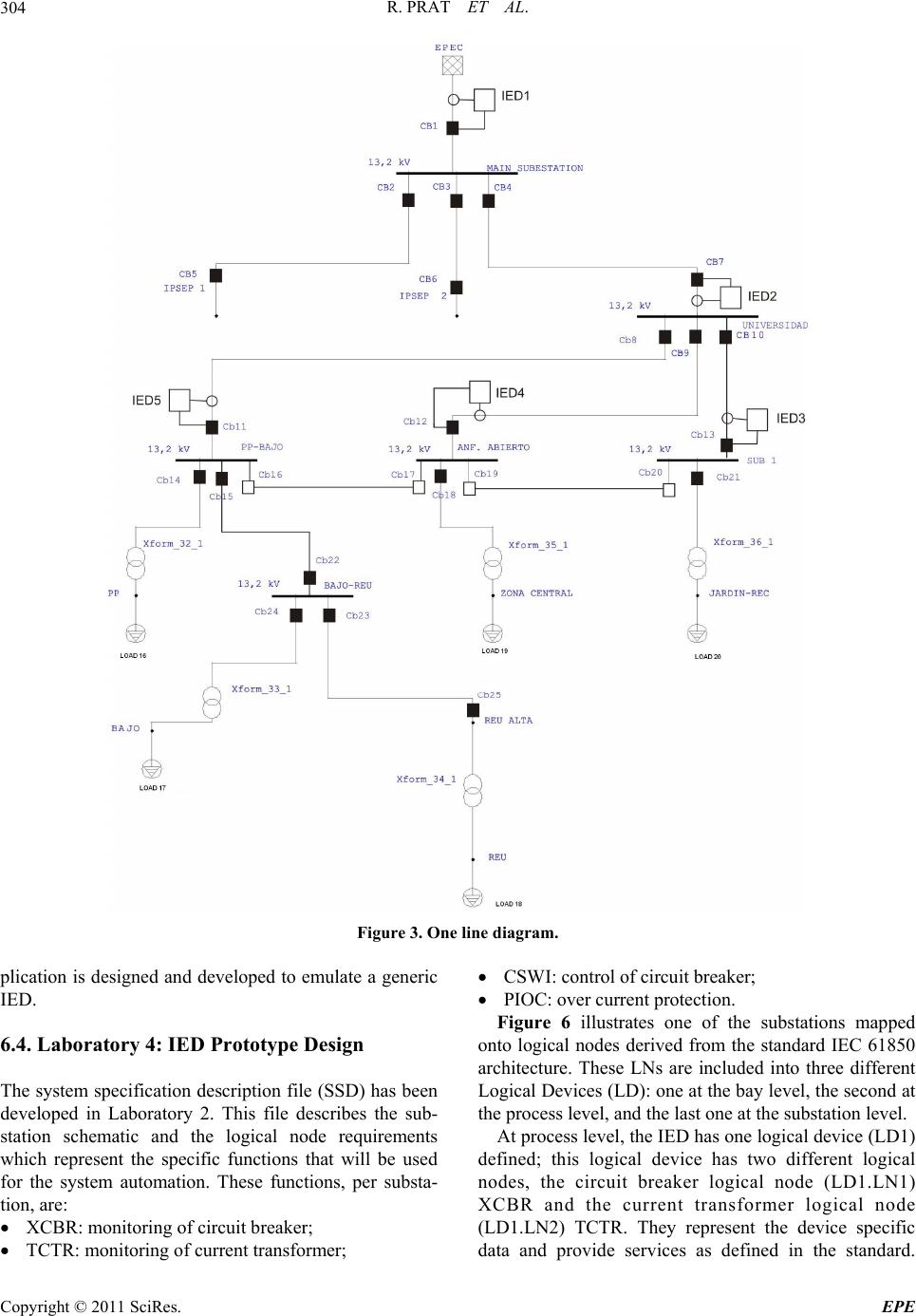 R. PRAT ET AL. Copyright © 2011 SciRes. EPE 304 Figure 3. One line diagram. CSWI: control of circu it breaker; plication is designed and developed to emulate a generic IED. PIOC: over current protection. Figure 6 illustrates one of the substations mapped onto logical nodes derived from the standard IEC 61850 architecture. These LNs are included into three different Logical Devices (LD): one at the bay level, the second at the process level, and the last one at the substation level. At process level, the IED has one logical device (LD1) defined; this logical device has two different logical nodes, the circuit breaker logical node (LD1.LN1) XCBR and the current transformer logical node (LD1.LN2) TCTR. They represent the device specific data and provide services as defined in the standard. 6.4. Laboratory 4: IED Prototype Design The system specification description file (SSD) has been developed in Laboratory 2. This file describes the sub- station schematic and the logical node requirements which represent the specific functions that will be used for the system automation. These functions, per substa- tion, are: XCBR: monitoring of circuit breaker; TCTR: monitoring of current transformer; 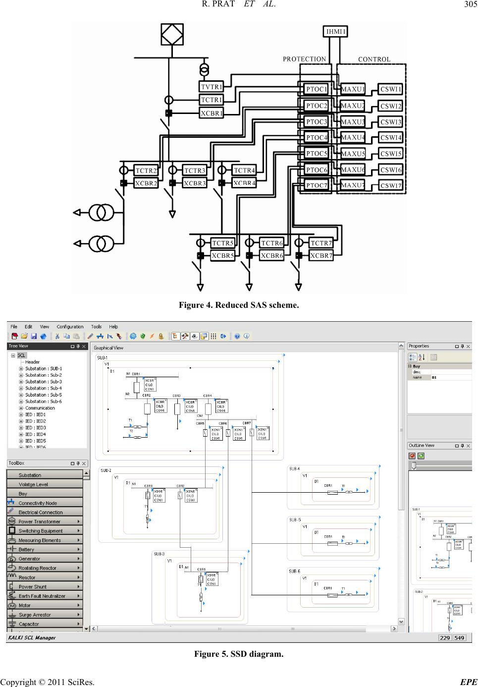 R. PRAT ET AL.305 Figure 4. Reduced SAS sc heme. Figure 5. SSD diagram. Copyright © 2011 SciRes. EPE 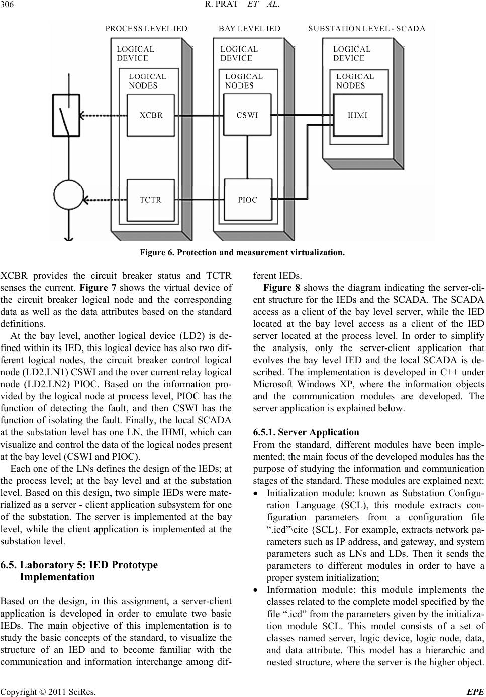 R. PRAT ET AL. 306 Figure 6. Protection and measurement virtualization. XCBR provides the circuit breaker status and TCTR senses the current. Figure 7 shows the virtual device of the circuit breaker logical node and the corresponding data as well as the data attributes based on the standard definitions. At the bay level, another logical device (LD2) is de- fined within its IED, this logical device has also two dif- ferent logical nodes, the circuit breaker control logical node (LD2.LN1) CSWI and the over current relay logical node (LD2.LN2) PIOC. Based on the information pro- vided by the logical node at process level, PIOC has the function of detecting the fault, and then CSWI has the function of isolating the fault. Finally, the local SCADA at the substation level has one LN, the IHMI, which can visualize and control the data of the logical nodes present at the bay level (CSWI and PIOC). Each one of the LNs defin es the design of the IEDs; at the process level; at the bay level and at the substation level. Based on this design, two simple IEDs were mate- rialized as a server - client application subsystem for one of the substation. The server is implemented at the bay level, while the client application is implemented at the substation level. 6.5. Laboratory 5: IED Prototype Implementation Based on the design, in this assignment, a server-client application is developed in order to emulate two basic IEDs. The main objective of this implementation is to study the basic concepts of the standard, to visualize the structure of an IED and to become familiar with the communication and information interchange among dif- ferent IEDs. Figure 8 shows the diagram indicating the server-cli- ent structure for the IEDs and the SCADA. The SCADA access as a client of the bay level server, while the IED located at the bay level access as a client of the IED server located at the process level. In order to simplify the analysis, only the server-client application that evolves the bay level IED and the local SCADA is de- scribed. The implementation is developed in C++ under Microsoft Windows XP, where the information objects and the communication modules are developed. The server application is explained below. 6.5.1. Server Appl i ca ti o n From the standard, different modules have been imple- mented; the main focus of the developed modules has the purpose of studying the information and communication stages of the standard. These modules are explained next: Initialization module: known as Substation Configu- ration Language (SCL), this module extracts con- figuration parameters from a configuration file “.icd”\cite {SCL}. For example, extracts network pa- rameters such as IP address, and gateway, and system parameters such as LNs and LDs. Then it sends the parameters to different modules in order to have a proper system initialization; Information module: this module implements the classes related to the complete model specified by the file “.icd” from the parameters given by the in itializa- tion module SCL. This model consists of a set of classes named server, logic device, logic node, data, and data attribute. This model has a hierarchic and nested struct ure, wh ere the s erver is the higher obje ct. Copyright © 2011 SciRes. EPE 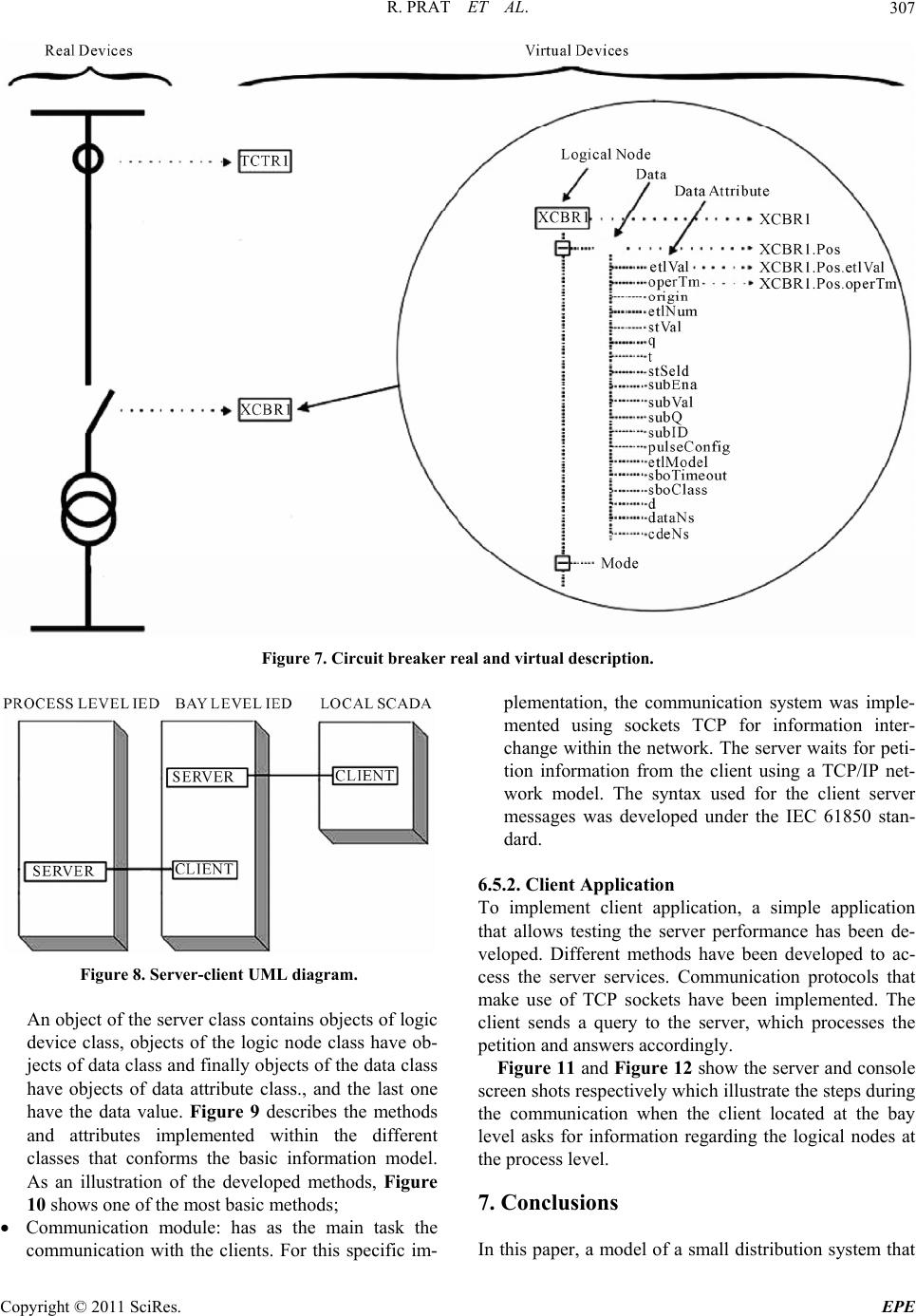 R. PRAT ET AL. Copyright © 2011 SciRes. EPE 307 Figure 7. Circui t br eaker real and virtual desc ription. Figure 8. Server-client UML diagram. An object of the server class contains objects of logic device class, objects of the logic node class have ob- jects of data class and finally objects of the data class have objects of data attribute class., and the last one have the data value. Figure 9 describes the methods and attributes implemented within the different classes that conforms the basic information model. As an illustration of the developed methods, Figure 10 shows one of the most basic methods; Communication module: has as the main task the communication with the clients. For this specific im- plementation, the communication system was imple- mented using sockets TCP for information inter- change within the network. The server waits for peti- tion information from the client using a TCP/IP net- work model. The syntax used for the client server messages was developed under the IEC 61850 stan- dard. 6.5.2. Client Appl i c ation To implement client application, a simple application that allows testing the server performance has been de- veloped. Different methods have been developed to ac- cess the server services. Communication protocols that make use of TCP sockets have been implemented. The client sends a query to the server, which processes the petition and answers accordingly. Figure 11 and Figure 12 show the server and console screen shots respectively which illustrate the steps during the communication when the client located at the bay level asks for information regarding the logical nodes at the process level. 7. Conclusions In this paper, a model of a small distribution system that  R. PRAT ET AL. 308 Figure 9. Information model UML diagram. Figure 10. Method GetServerDirectory. Figure 11. Server application at process level. plans to utilize new communication technology follow- ing the IEC 61850 standard is implemented. It illustrates basic concepts of the norm and describes how these con- cepts can be used in the development and implementa- tion of tools related to SAS. Moreover, Standard IEC 61850 based IED modules were created and functionality improvements of SAS based on the standar d were discussed. The modules implemented over standard protocols il- lustrate that the standardization of data names, the crea- Copyright © 2011 SciRes. EPE  R. PRAT ET AL. Copyright © 2011 SciRes. EPE 309 Figure 12. Client application at bay level. [6] EPRI, “Guidelines for Implementing Substation Automa- tion Using IEC61850, the International Power System Information Modeling Standard,” Electric Power Re- search Institute, Palo Alto, 2004. tion of a comprehensive set of services, and the defini- tion of a process bus offer benefits for the design of a substation automatio n system. Finally, the implementation was developed based on a set of didactic laboratories providing undergraduate as well as graduate students the opportunity to carry out projects and laboratory work on communications in a real distribution system. The “real-world” nature of the implemented projects, and the exposition of student to a real substation, make a very valuable contribution to any power engineering curriculum [7] R. Venkata, S. Pahwa and R. Christie, “What Future Dis- tribution Engineers Need to Learn,” IEEE Transactions on Power Systems, Vol. 19, No. 1, 2004, pp. 17-23. doi:10.1109/TPWRS.2003.821017 [8] R. Kirkman, “Development in Substation Automation Systems,” Proceedings of International Conference on Intelligent Systems Applications to Power Systems, Toki Messe, 5-8 November 2007, pp. 1-6. doi:10.1109/ISAP.2007.4441690 8. References [9] T. Sidhu and Y. Yujie, “Modelling and Simulation for Performance Evaluation of IEC61850-Based Substation Communication Systems,” IEEE Transactions on Power Delivery, Vol. 22, No. 3, 2007, pp. 1482-1489. doi:10.1109/TPWRD.2006.886788 [1] V. Gungor and F. Lambert, “A Survey on Communica- tion Networks for Electric System Automation,” Com- puter Networks, Vol. 5, No. 1, 2006, pp. 877-897. doi:10.1016/j.comnet.2006.01.005 [10] IEC-61850-6, “Communication Networks and Systems in Substations, Part 6: Configuration Description Language for Communication in Electrical Substations Related to IEDs,” International Electrotechnical Commission, Ge- neva, SW, 2004. [2] M. Kezunovic, “Substation Automation Research Fron- tiers,” Proceedings of the Power Systems Conference and Exposition, Seattle, 15-18 March 2009, pp. 1-2. doi:10.1109/PSCE.2009.4840104 [11] R. E. Mackiewicz, “Overview of IEC61850 and Bene- fits,” 2006 IEEE Power Systems Conference and Exposi- tion, Atlanta, 29 October-1 November 2006, pp. 623-630. doi:10.1109/PSCE.2006.296392 [3] N. Nair and L. Zhang, “Smartgrid: Future Networks for New Zealand Power Systems Incorporation Distributed Generation,” Energy Policy, Vol. 37, No. 9, 2009, pp. 3418-3427. doi:10.1016/j.enpol.2009.03.025 [12] IEC-61850-7, “Communication Networks and Systems in Substations, Part 7-420: Basic Communication Struc- ture—Distributed Energy Resources Logical Nodes,” In- ternational Electrotechnical Commission, Geneva, 2009. [4] T. J. Hammons, “Integrating Renewable Energy Sources into European Grids,” Electric Power and Energy Sys- tems, Vol. 30, No. 8, 2008, pp. 462-475. doi:10.1016/j.ijepes.2008.04.010 [13] KalkiManager. “Software SCL,” 2011. www.kalkitech.com [5] D. Dollen, “Report to NIST on the Smart Grid Interop- erability Standards Roadmap,” Electric Power Research Institute, Palo Alto, June 2009. |