Paper Menu >>
Journal Menu >>
 Energy and Power Engineering, 2011, 3, 262-270 doi:10.4236/epe.2011.33033 Published Online July 2011 (http://www.SciRP.org/journal/epe) Copyright © 2011 SciRes. EPE Double Multiple Stream Tube Model and Numerical Analysis of Vertical Axis W ind Turbine Habtamu Beri, Yingxue Yao Department of Manufacturing and Automation, Harbin Institute of Technology, Harbin, China E-mail: habtamu_beri@yahoo.com Received April 18, 2011; revised May 2, 2011; accepted May 11, 2011 Abstract The present paper contributes to the modeling of unsteady flow analysis of vertical axis wind turbine (VAWT). Double multiple stream tube (DSMT) model was applied for the performance prediction of straight bladed fixed pitch VAWT using NACA0018 airfoil at low wind speed. A moving mesh technique was used to investigate two-dimensional unsteady flow around the same VAWT model with NACA0018 airfoil modified to be flexible at 15˚ from the main blade axis of the turbine at the trailing edge located about 70% of the blade chord length using fluent solving Reynolds average Navier-strokes equation. The results obtained from DMST model and the simulation results were then compared. The result shows that the CFD simulation with airfoil modified has shown better performance at low tip speed ratios for the modeled tur- bine. Keywords: Wind Turbine, Actuator Disk, Momentum Model, Stream Tube, VAWT, CFD 1. Introduction Over the past decade the wind energy conversion to elec- tric power has experienced significant progress in the world. This was made possible by considerable engi- neering research and development of wind machines with emphasis on the aerodynamic, structural, and sys- tems characteristics. The Darrieus rotor VAWT offers a mechanically and structurally simple method of harness- ing the energy of the wind. Although first patented in 1931 it has been intensively developed only since 1970, primarily by the National Research Council of Canada, 2 Sandia National Laboratories, and by others in Europe [1]. In recent years an increasing demand in decentralized power plants is observed renewing the interest in Vertical Axis Wind Turbines (VAWT). The VAWT offers several advantages when compared to the more conventional Horizontal-Axis (HAWT) machines. The VAWT is in- herently Omni-directional and hence obviates the need to provide a yawing mechanism for keeping the machine turned into the wind. The transmission and electrical gen- eration equipment can be located at ground level, thus tending toward a simpler, lighter structure. The VAWT is also better able to withstand high winds. In one sense, the price paid for structural simplicity is aerodynamic com- plexity: VAWT aerodynamics is inherently unsteady, and highly nonlinear. However, the relatively recent devel- opment of several methods capable of predicting steady- state performance has greatly in-creased our understand- ing of VAWT aerodynamics [2]. 1.1. Power Obtained from Wind Turbine A simple model, generally attributed to Betz (1926) cited in [3], can be used to determine the power from an ideal turbine rotor, the thrust of the wind on the ideal rotor and the effect of the rotor operation on the local wind field. This simple model is based on a linear momentum theory. The analysis assumes a control volume, in which the control volume boundaries are the surface of a stream tube and two cross-sections of the stream tube (see Fig- ure 1). The only flow is across the ends of the stream tube. The turbine is represented by a uniform “actuator disk” which creates a discontinuity of pressure in the stream tube of air flowing through it. Note that this analysis is not limited to any particular type of wind tur- bine. This analysis uses the following assumptions: Homogenous, incompressible, steady state fluid flow; No frictional drag; An infinite number of blades; Uniform thrust over the disk or rotor area; 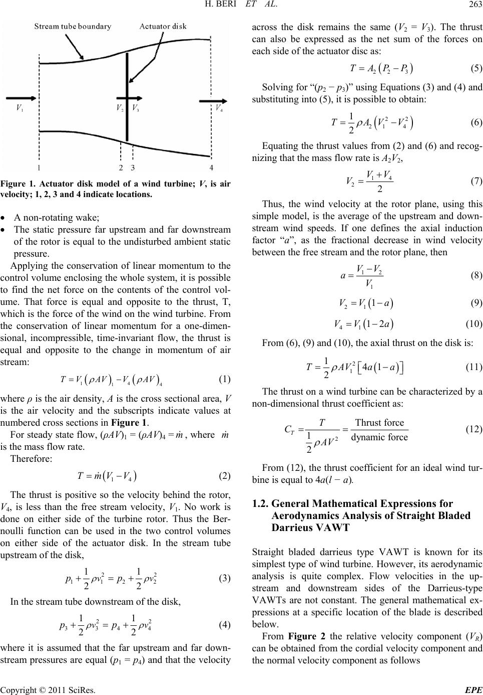 H. BERI ET AL.263 Figure 1. Actuator disk model of a wind turbine; V, is air velocity; 1, 2, 3 and 4 indicate locations. A non-rotating wake; The static pressure far upstream and far downstream of the rotor is equal to the undisturbed ambient static pressure. Applying the conservation of linear momentum to the control volume enclosing the whole system, it is possible to find the net force on the contents of the control vol- ume. That force is equal and opposite to the thrust, T, which is the force of the wind on the wind turbine. From the conservation of linear momentum for a one-dimen- sional, incompressible, time-invariant flow, the thrust is equal and opposite to the change in momentum of air stream: 14 1 TV AVVAV 4 (1) where ρ is the air density, A is the cross sectional area, V is the air velocity and the subscripts indicate values at numbered cross sections in Figure 1. For steady state flow, (ρAV)1 = (ρAV)4 =, where is the mass flow rate. m m Therefore: 14 TmVV (2) The thrust is positive so the velocity behind the rotor, V4, is less than the free stream velocity, V1. No work is done on either side of the turbine rotor. Thus the Ber- noulli function can be used in the two control volumes on either side of the actuator disk. In the stream tube upstream of the disk, 2 112 11 22 vpp 2 2 v (3) In the stream tube downstream of the disk, 2 334 11 22 vpp 2 4 v (4) where it is assumed that the far upstream and far down- stream pressures are equal (p1 = p4) and that the velocity across the disk remains the same (V2 = V3). The thrust can also be expressed as the net sum of the forces on each side of the actuator disc as: 22 3 TAPP (5) Solving for “(p2 − p3)” using Equations (3) and (4) and substituting into (5), it is possible to obtain: 22 21 4 1 2 TAVV (6) Equating the thrust values from (2) and (6) and recog- nizing that the mass flow rate is A2V2, 14 22 VV V (7) Thus, the wind velocity at the rotor plane, using this simple model, is the average of the upstream and down- stream wind speeds. If one defines the axial induction factor “a”, as the fractional decrease in wind velocity between the free stream and the rotor plane, then 12 1 VV aV (8) 21 1VV a (9) 41 12VV a (10) From (6), (9) and (10), the axial thrust on the disk is: 2 1 141 2 TAVaa (11) The thrust on a wind turbine can be characterized by a non-dimensional thrust coefficient as: 2 Thrust force 1dynamic force 2 T T C AV (12) From (12), the thrust coefficient for an ideal wind tur- bine is equal to 4a(l − a). 1.2. General Mathematical Expressions for Aerodynamics Analysis of Straight Bladed Darrieus VAWT Straight bladed darrieus type VAWT is known for its simplest type of wind turbine. However, its aerodynamic analysis is quite complex. Flow velocities in the up- stream and downstream sides of the Darrieus-type VAWTs are not constant. The general mathematical ex- pressions at a specific location of the blade is described below. From Figure 2 the relative velocity component (VR) can be obtained from the cordial velocity component and the normal velocity component as follows Copyright © 2011 SciRes. EPE 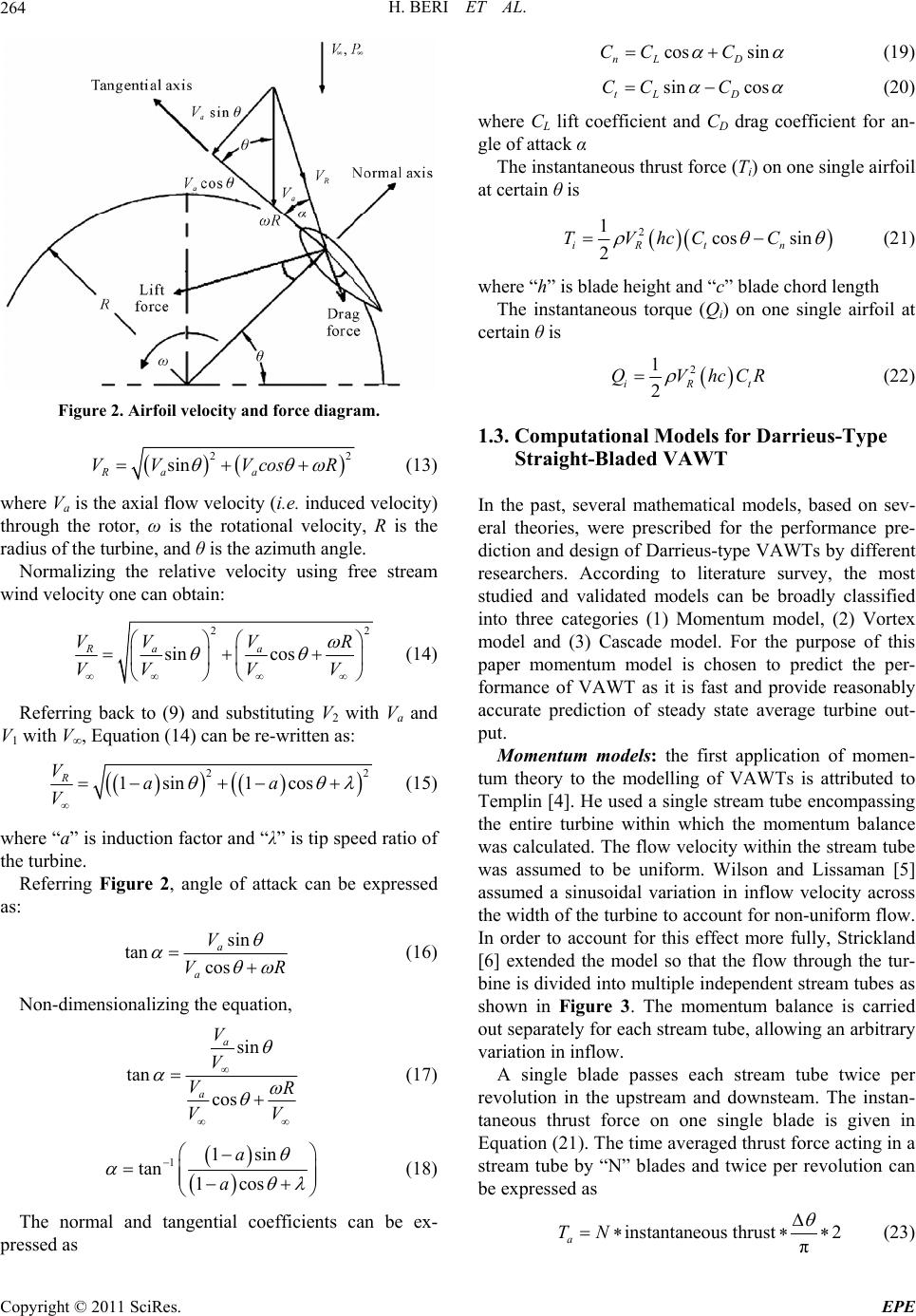 H. BERI ET AL. 264 Figure 2. Airfoil velocity and force diagram. 22 sin Ra a VV VcosR (13) where Va is the axial flow velocity (i.e. induced velocity) through the rotor, ω is the rotational velocity, R is the radius of the turbine, and θ is the azimuth angle. Normalizing the relative velocity using free stream wind velocity one can obtain: 2 sin cos aa RVV VR VVV V 2 (14) Referring back to (9) and substituting V2 with Va and V1 with V∞, Equation (14) can be re-written as: 2 1sin 1cos R Vaa V 2 (15) where “a” is induction factor and “λ” is tip speed ratio of the turbine. Referring Figure 2, angle of attack can be expressed as: sin tan cos a a V VR (16) Non-dimensionalizing the equation, sin tan cos a a V V VR VV (17) 11sin tan 1cos a a (18) The normal and tangential coefficients can be ex- pressed as cos sin nL D CC C (19) sin cos tL D CC C (20) where CL lift coefficient and CD drag coefficient for an- gle of attack α The instantaneous thrust force (Ti) on one single airfoil at certain θ is 2 1cos sin 2 iR tn TVhcC C (21) where “h” is blade height and “c” blade chord length The instantaneous torque (Qi) on one single airfoil at certain θ is 2 1 2 iR QVhcC t R (22) 1.3. Computational Models for Darrieus-Type Straight-Bladed VAWT In the past, several mathematical models, based on sev- eral theories, were prescribed for the performance pre- diction and design of Darrieus-type VAWTs by different researchers. According to literature survey, the most studied and validated models can be broadly classified into three categories (1) Momentum model, (2) Vortex model and (3) Cascade model. For the purpose of this paper momentum model is chosen to predict the per- formance of VAWT as it is fast and provide reasonably accurate prediction of steady state average turbine out- put. Momentum models: the first application of momen- tum theory to the modelling of VAWTs is attributed to Templin [4]. He used a single stream tube encompassing the entire turbine within which the momentum balance was calculated. The flow velocity within the stream tube was assumed to be uniform. Wilson and Lissaman [5] assumed a sinusoidal variation in inflow velocity across the width of the turbine to account for non-uniform flow. In order to account for this effect more fully, Strickland [6] extended the model so that the flow through the tur- bine is divided into multiple independent stream tubes as shown in Figure 3. The momentum balance is carried out separately for each stream tube, allowing an arbitrary variation in inflow. A single blade passes each stream tube twice per revolution in the upstream and downsteam. The instan- taneous thrust force on one single blade is given in Equation (21). The time averaged thrust force acting in a stream tube by “N” blades and twice per revolution can be expressed as instantaneous thrust2 π a TN (23) Copyright © 2011 SciRes. EPE 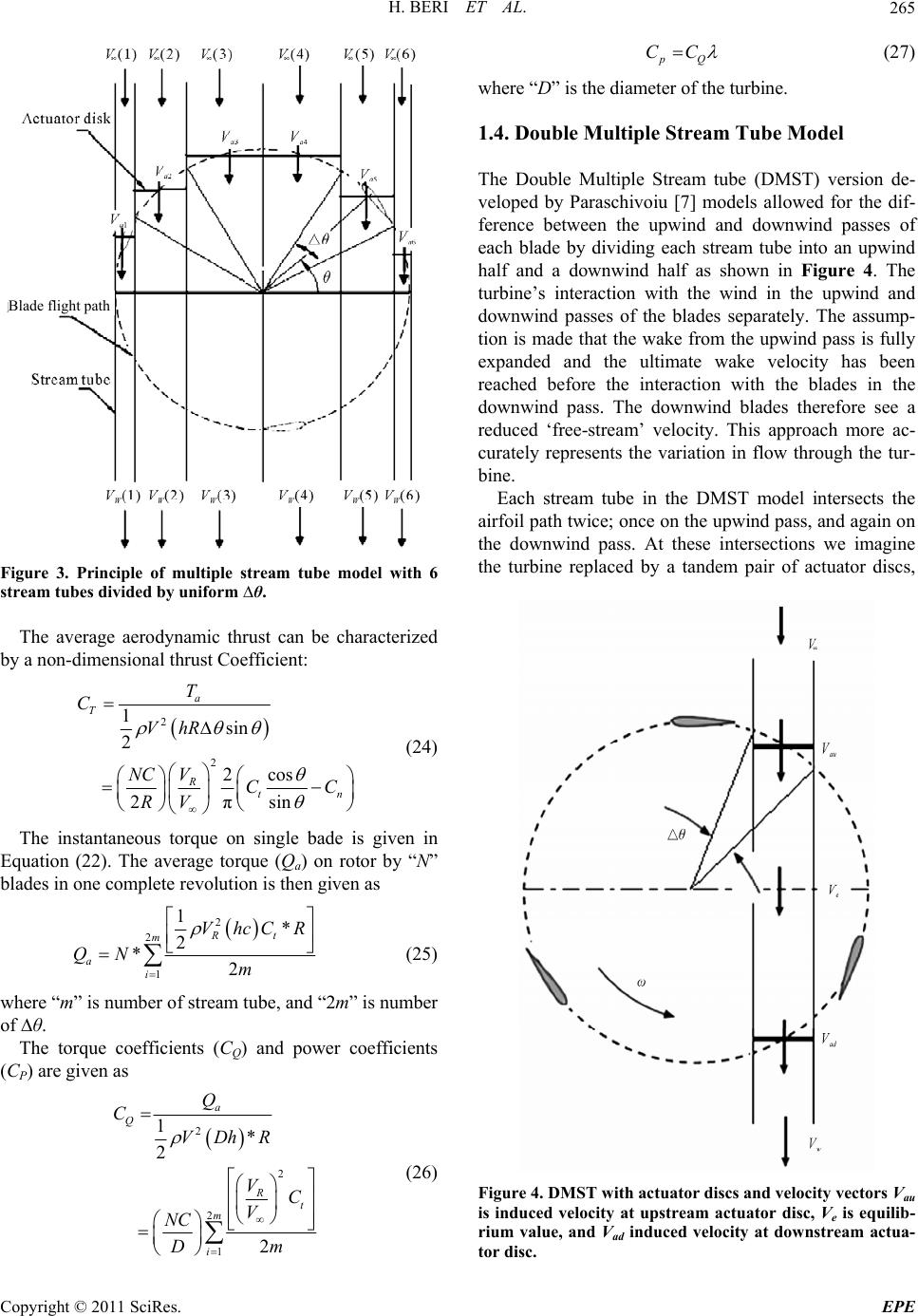 H. BERI ET AL.265 Blade flight path Figure 3. Principle of multiple stream tube model with 6 stream tubes divided by uniform ∆θ. The average aerodynamic thrust can be characterized by a non-dimensional thrust Coefficient: 2 2 1sin 2 2cos 2πsin a T R tn T C VhR V NC CC RV (24) The instantaneous torque on single bade is given in Equation (22). The average torque (Qa) on rotor by “N” blades in one complete revolution is then given as 2 2 1 1* 2 *2 Rt m a i VhcCR QN m (25) where “m” is number of stream tube, and “2m” is number of ∆θ. The torque coefficients (CQ) and power coefficients (CP) are given as 2 2 2 1 1* 2 2 a Q R t m i Q C VDhR VC V NC Dm (26) pQ CC (27) where “D” is the diameter of the turbine. 1.4. Double Multiple Stream Tube Model The Double Multiple Stream tube (DMST) version de- veloped by Paraschivoiu [7] models allowed for the dif- ference between the upwind and downwind passes of each blade by dividing each stream tube into an upwind half and a downwind half as shown in Figure 4. The turbine’s interaction with the wind in the upwind and downwind passes of the blades separately. The assump- tion is made that the wake from the upwind pass is fully expanded and the ultimate wake velocity has been reached before the interaction with the blades in the downwind pass. The downwind blades therefore see a reduced ‘free-stream’ velocity. This approach more ac- curately represents the variation in flow through the tur- bine. Each stream tube in the DMST model intersects the airfoil path twice; once on the upwind pass, and again on the downwind pass. At these intersections we imagine the turbine replaced by a tandem pair of actuator discs, Figure 4. DMST with actuator discs and velocity vectors Vau is induced velocity at upstream actuator disc, Ve is equilib- rium value, and Vad induced velocity at downstream actua- tor disc. Copyright © 2011 SciRes. EPE 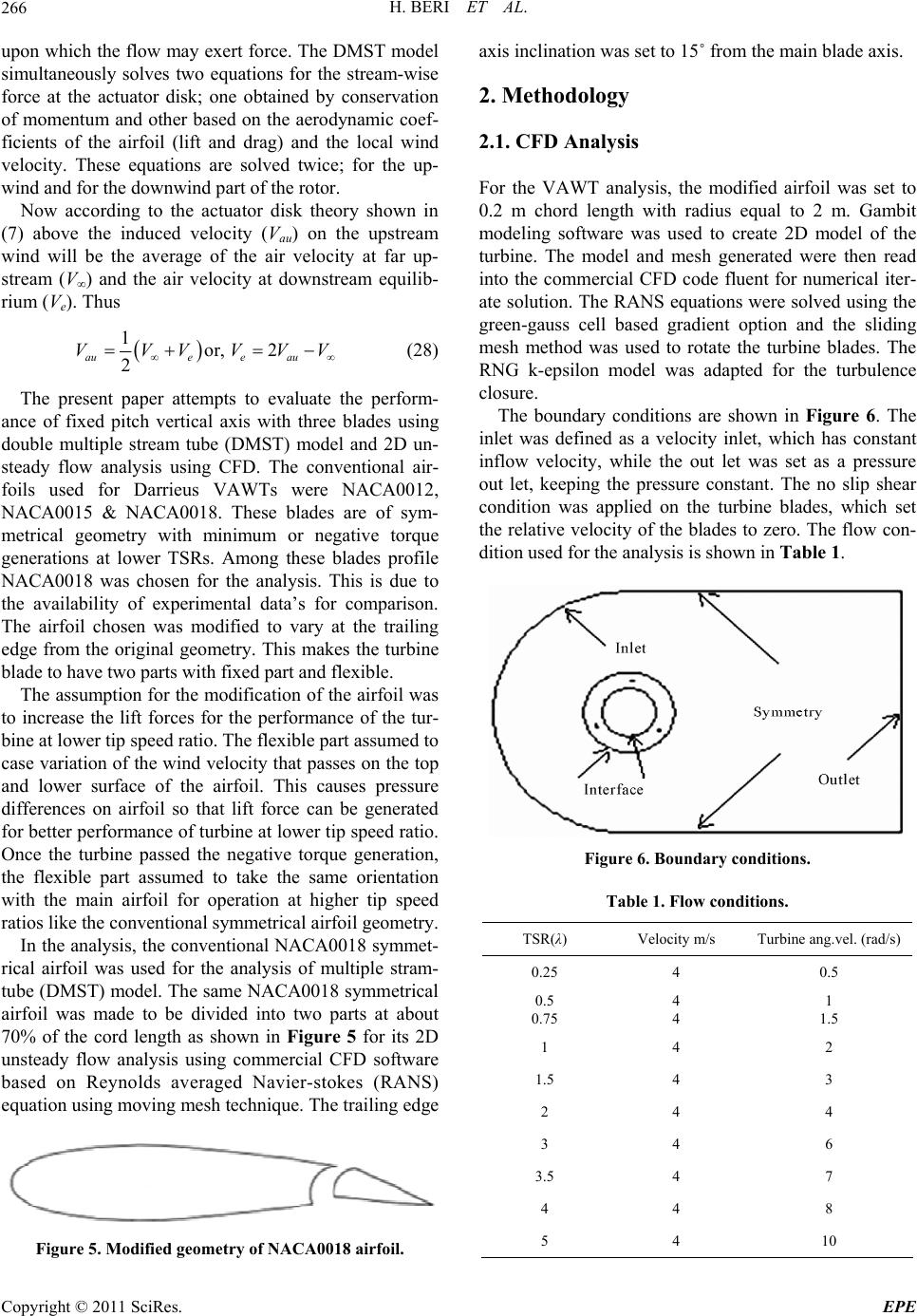 H. BERI ET AL. 266 upon which the flow may exert force. The DMST model simultaneously solves two equations for the stream-wise force at the actuator disk; one obtained by conservation of momentum and other based on the aerodynamic coef- ficients of the airfoil (lift and drag) and the local wind velocity. These equations are solved twice; for the up- wind and for the downwind part of the rotor. Now according to the actuator disk theory shown in (7) above the induced velocity (Vau) on the upstream wind will be the average of the air velocity at far up- stream (V∞) and the air velocity at downstream equilib- rium (Ve). Thus 1 or, 2 2 auee au VVVVV V (28) The present paper attempts to evaluate the perform- ance of fixed pitch vertical axis with three blades using double multiple stream tube (DMST) model and 2D un- steady flow analysis using CFD. The conventional air- foils used for Darrieus VAWTs were NACA0012, NACA0015 & NACA0018. These blades are of sym- metrical geometry with minimum or negative torque generations at lower TSRs. Among these blades profile NACA0018 was chosen for the analysis. This is due to the availability of experimental data’s for comparison. The airfoil chosen was modified to vary at the trailing edge from the original geometry. This makes the turbine blade to have two parts with fixed part and flexible. The assumption for the modification of the airfoil was to increase the lift forces for the performance of the tur- bine at lower tip speed ratio. The flexible part assumed to case variation of the wind velocity that passes on the top and lower surface of the airfoil. This causes pressure differences on airfoil so that lift force can be generated for better performance of turbine at lower tip speed ratio. Once the turbine passed the negative torque generation, the flexible part assumed to take the same orientation with the main airfoil for operation at higher tip speed ratios like the conventional symmetrical airfoil geometry. In the analysis, the conventional NACA0018 symmet- rical airfoil was used for the analysis of multiple stram- tube (DMST) model. The same NACA0018 symmetrical airfoil was made to be divided into two parts at about 70% of the cord length as shown in Figure 5 for its 2D unsteady flow analysis using commercial CFD software based on Reynolds averaged Navier-stokes (RANS) equation using moving mesh technique. The trailing edge Figure 5. Modified geometry of NACA0018 airfoil. axis inclination was set to 15˚ from the main blade axis. 2. Methodology 2.1. CFD Analysis For the VAWT analysis, the modified airfoil was set to 0.2 m chord length with radius equal to 2 m. Gambit modeling software was used to create 2D model of the turbine. The model and mesh generated were then read into the commercial CFD code fluent for numerical iter- ate solution. The RANS equations were solved using the green-gauss cell based gradient option and the sliding mesh method was used to rotate the turbine blades. The RNG k-epsilon model was adapted for the turbulence closure. The boundary conditions are shown in Figure 6. The inlet was defined as a velocity inlet, which has constant inflow velocity, while the out let was set as a pressure out let, keeping the pressure constant. The no slip shear condition was applied on the turbine blades, which set the relative velocity of the blades to zero. The flow con- dition used for the analysis is shown in Table 1. Figure 6. Boundary conditions. Table 1. Flow conditions. TSR(λ) Velocity m/s Turbine ang.vel. (rad/s) 0.25 4 0.5 0.5 0.75 4 4 1 1.5 1 4 2 1.5 4 3 2 4 4 3 4 6 3.5 4 7 4 4 8 5 4 10 Copyright © 2011 SciRes. EPE 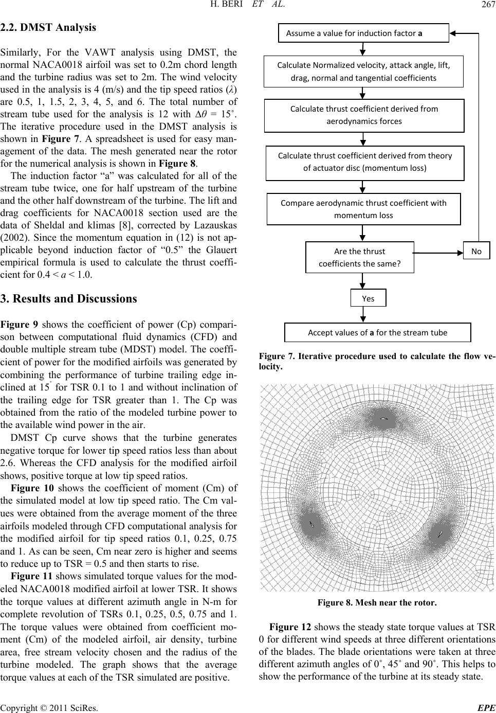 H. BERI ET AL.267 2.2. DMST Analysis Similarly, For the VAWT analysis using DMST, the normal NACA0018 airfoil was set to 0.2m chord length and the turbine radius was set to 2m. The wind velocity used in the analysis is 4 (m/s) and the tip speed ratios (λ) are 0.5, 1, 1.5, 2, 3, 4, 5, and 6. The total number of stream tube used for the analysis is 12 with ∆θ = 15˚. The iterative procedure used in the DMST analysis is shown in Figure 7. A spreadsheet is used for easy man- agement of the data. The mesh generated near the rotor for the numerical analysis is shown in Figure 8. The induction factor “a” was calculated for all of the stream tube twice, one for half upstream of the turbine and the other half downstream of the turbine. The lift and drag coefficients for NACA0018 section used are the data of Sheldal and klimas [8], corrected by Lazauskas (2002). Since the momentum equation in (12) is not ap- plicable beyond induction factor of “0.5” the Glauert empirical formula is used to calculate the thrust coeffi- cient for 0.4 < a < 1.0. 3. Results and Discussions Figure 9 shows the coefficient of power (Cp) compari- son between computational fluid dynamics (CFD) and double multiple stream tube (MDST) model. The coeffi- cient of power for the modified airfoils was generated by combining the performance of turbine trailing edge in- clined at 15˚ for TSR 0.1 to 1 and without inclination of the trailing edge for TSR greater than 1. The Cp was obtained from the ratio of the modeled turbine power to the available wind power in the air. DMST Cp curve shows that the turbine generates negative torque for lower tip speed ratios less than about 2.6. Whereas the CFD analysis for the modified airfoil shows, positive torque at low tip speed ratios. Figure 10 shows the coefficient of moment (Cm) of the simulated model at low tip speed ratio. The Cm val- ues were obtained from the average moment of the three airfoils modeled through CFD computational analysis for the modified airfoil for tip speed ratios 0.1, 0.25, 0.75 and 1. As can be seen, Cm near zero is higher and seems to reduce up to TSR = 0.5 and then starts to rise. Figure 11 shows simulated torque values for the mod- eled NACA0018 modified airfoil at lower TSR. It shows the torque values at different azimuth angle in N-m for complete revolution of TSRs 0.1, 0.25, 0.5, 0.75 and 1. The torque values were obtained from coefficient mo- ment (Cm) of the modeled airfoil, air density, turbine area, free stream velocity chosen and the radius of the turbine modeled. The graph shows that the average torque values at each of the TSR simulated are positive. Assumeavalueforinductionfactora CalculateNormalizedvelocity,attackangle,lift, drag,no r ma landtangentialcoefficients Calculatethrustcoefficientderivedfrom aerodynamicsforces Calculatethrustcoefficientderivedfromtheory ofactuatordisc(momentumloss) Compareaerody na m ic thrustcoefficientwith momentumloss Arethethrust coefficientsthesame? Acceptvaluesofaforthestreamtube No Yes Figure 7. Iterative procedure used to calculate the flow ve- locity. Figure 8. Mesh near the rotor. Figure 12 shows the steady state torque values at TSR 0 for different wind speeds at three different orientations of the blades. The blade orientations were taken at three different azimuth angles of 0˚, 45˚ and 90˚. This helps to show the performance of the turbine at its steady state. Copyright © 2011 SciRes. EPE 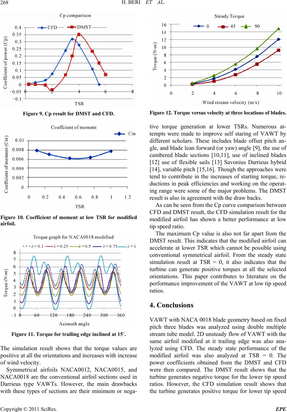 H. BERI ET AL. 268 Figure 9. Cp result for DMST and CFD. Figure 10. Coefficient of moment at low TSR for modified airfoil. Figure 11. Torque for trailing edge inclined at 15˚. The simulation result shows that the torque values are positive at all the orientations and increases with increase of wind velocity. Symmetrical airfoils NACA0012, NACA0015, and NACA0018 are the conventional airfoil sections used in Darrieus type VAWTs. However, the main drawbacks with these types of sections are their minimum or nega- Figure 12. Torque versus velocity at three locations of blades. tive torque generation at lower TSRs. Numerous at- tempts were made to improve self staring of VAWT by different scholars. These includes blade offset pitch an- gle, and blade lean forward (or yaw) angle [9], the use of cambered blade sections [10,11], use of inclined blades [12] use of flexible sails [13] Savonius Darrieus hybrid [14], variable pitch [15,16]. Though the approaches were tend to contribute in the increases of starting torque, re- ductions in peak efficiencies and working on the operat- ing range were some of the major problems. The DMST result is also in agreement with the draw backs. As can be seen from the Cp curve comparison between CFD and DMST result, the CFD simulation result for the modified airfoil has shown a better performance at low tip speed ratio. The maximum Cp value is also not far apart from the DMST result. This indicates that the modified airfoil can accelerate at lower TSR which cannot be possible using conventional symmetrical airfoil. From the steady state simulation result at TSR = 0, it also indicates that the turbine can generate positive torques at all the selected orientations. This paper contributes to literature on the performance improvement of the VAWT at low tip speed ratios. 4. Conclusions VAWT with NACA 0018 blade geometry based on fixed pitch three blades was analyzed using double multiple stream tube model. 2D unsteady flow of VAWT with the same airfoil modified at it trailing edge was also ana- lyzed using CFD. The steady state performance of the modified airfoil was also analyzed at TSR = 0. The power coefficients obtained from the DMST and CFD were then compared. The DMST result shows that the turbine generates negative torque for the lower tip speed ratios. However, the CFD simulation result shows that the turbine generates positive torque for lower tip speed Copyright © 2011 SciRes. EPE 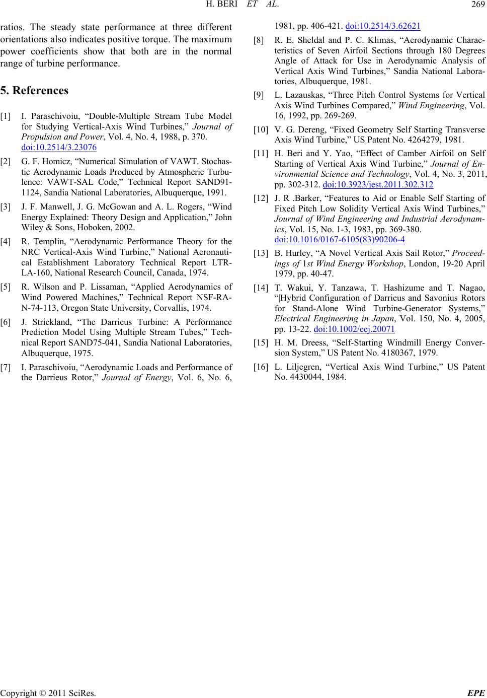 H. BERI ET AL. Copyright © 2011 SciRes. EPE 269 ratios. The steady state performance at three different orientations also indicates positive torque. The maximum power coefficients show that both are in the normal range of turbine performance. 5. References [1] I. Paraschivoiu, “Double-Multiple Stream Tube Model for Studying Vertical-Axis Wind Turbines,” Journal of Propulsion and Power, Vol. 4, No. 4, 1988, p. 370. doi:10.2514/3.23076 [2] G. F. Homicz, “Numerical Simulation of VAWT. Stochas- tic Aerodynamic Loads Produced by Atmospheric Turbu- lence: VAWT-SAL Code,” Technical Report SAND91- 1124, Sandia National Laboratories, Albuquerque, 1991. [3] J. F. Manwell, J. G. McGowan and A. L. Rogers, “Wind Energy Explained: Theory Design and Application,” John Wiley & Sons, Hoboken, 2002. [4] R. Templin, “Aerodynamic Performance Theory for the NRC Vertical-Axis Wind Turbine,” National Aeronauti- cal Establishment Laboratory Technical Report LTR- LA-160, National Research Council, Canada, 1974. [5] R. Wilson and P. Lissaman, “Applied Aerodynamics of Wind Powered Machines,” Technical Report NSF-RA- N-74-113, Oregon State University, Corvallis, 1974. [6] J. Strickland, “The Darrieus Turbine: A Performance Prediction Model Using Multiple Stream Tubes,” Tech- nical Report SAND75-041, Sandia National Laboratories, Albuquerque, 1975. [7] I. Paraschivoiu, “Aerodynamic Loads and Performance of the Darrieus Rotor,” Journal of Energy, Vol. 6, No. 6, 1981, pp. 406-421. doi:10.2514/3.62621 [8] R. E. Sheldal and P. C. Klimas, “Aerodynamic Charac- teristics of Seven Airfoil Sections through 180 Degrees Angle of Attack for Use in Aerodynamic Analysis of Vertical Axis Wind Turbines,” Sandia National Labora- tories, Albuquerque, 1981. [9] L. Lazauskas, “Three Pitch Control Systems for Vertical Axis Wind Turbines Compared,” Wind Engineering, Vol. 16, 1992, pp. 269-269. [10] V. G. Dereng, “Fixed Geometry Self Starting Transverse Axis Wind Turbine,” US Patent No. 4264279, 1981. [11] H. Beri and Y. Yao, “Effect of Camber Airfoil on Self Starting of Vertical Axis Wind Turbine,” Journal of En- vironmental Science and Technology, Vol. 4, No. 3, 2011, pp. 302-312. doi:10.3923/jest.2011.302.312 [12] J. R .Barker, “Features to Aid or Enable Self Starting of Fixed Pitch Low Solidity Vertical Axis Wind Turbines,” Journal of Wind Engineering and Industrial Aerodynam- ics, Vol. 15, No. 1-3, 1983, pp. 369-380. doi:10.1016/0167-6105(83)90206-4 [13] B. Hurley, “A Novel Vertical Axis Sail Rotor,” Proceed- ings of 1st Wind Energy Workshop, London, 19-20 April 1979, pp. 40-47. [14] T. Wakui, Y. Tanzawa, T. Hashizume and T. Nagao, “|Hybrid Configuration of Darrieus and Savonius Rotors for Stand-Alone Wind Turbine-Generator Systems,” Electrical Engineering in Japan, Vol. 150, No. 4, 2005, pp. 13-22. doi:10.1002/eej.20071 [15] H. M. Dreess, “Self-Starting Windmill Energy Conver- sion System,” US Patent No. 4180367, 1979. [16] L. Liljegren, “Vertical Axis Wind Turbine,” US Patent No. 4430044, 1984. 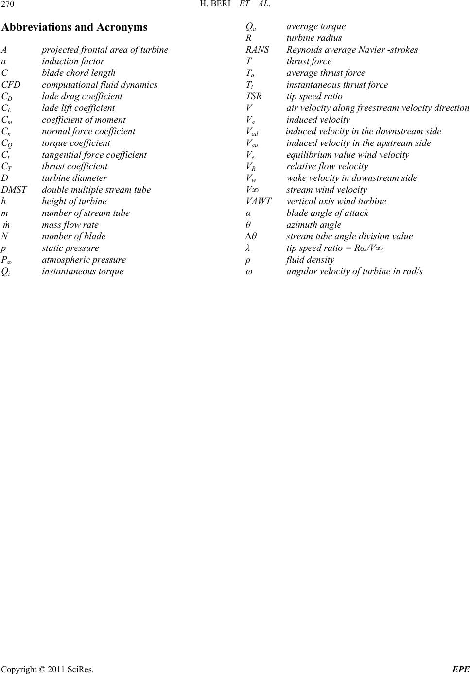 H. BERI ET AL. 270 Abbreviations and Acronyms A projected frontal area of turbine a induction factor C blade chord length CFD computational fluid dynamics CD lade drag coefficient CL lade lift coefficient Cm coefficient of moment Cn normal force coefficient CQ torque coefficient Ct tangential force coefficient CT thrust coefficient D turbine diameter DMST double multiple stream tube h height of turbine m number of stream tube m mass flow rate N number of blade p static pressure P∞ atmospheric pressure Qi instantaneous torque Qa average torque R turbine radius RANS Reynolds average Navier -strokes T thrust force Ta average thrust force Ti instantaneous thrust force TSR tip speed ratio V air velocity along freestream velocity direction Va induced velocity Vad induced velocity in the downstream side Vau induced velocity in the upstream side Ve equilibrium value wind velocity VR relative flow velocity Vw wake velocity in downstream side V∞ stream wind velocity VAWT vertical axis wind turbine α blade angle of attack θ azimuth angle ∆θ stream tube angle division value λ tip speed ratio = Rω/V∞ ρ fluid density ω angular velocity of turbine in rad/s Copyright © 2011 SciRes. EPE |

