America n Journal of Analy tic al Chemistry, 2011, 2, 363-370
doi:10.4236/ajac.2011.23044 Published Online July 2011 (http://www.scirp.org/journal/ajac)
Copyright © 2011 SciRes. AJAC
363
Analysis of Damaged Silicon Rubber Hose
Mosammad Shamsun Nahar*, Jing Zhang
Department of Environmental Biology and Chemistry, Graduate School of Science and Engineering,
University of Toyama, Toyama, Japan
E-mail: msnahar@sci.u-toyama.ac.jp
Received February 23, 2011; revised March 27, 2011; accepted April 15, 2011
Abstract
Recently, there have been many reports of silicon rubber (SR) hoses becoming brittle in juice factory wi thi n
one month of purchase. The damage is a new phenomenon, and its cause is unknown. We have collected the
damaged hoses attached to UHT sterilizer (ultra-high-temperature) in juice factory and examined them for
chemical changes. In addition, we have analyzed the hose-washing chemicals (NaOH and HNO3) that used
in juice factory and investigated the effect of NaOH and HNO3 on a new hose surface in an attempt to estab-
lish a probable chemical chain reaction that could attack of the Si-O-Si backbone and cause such degrada-
tion. According to WDXRF (Wavelength Dispersive X-Ray Fluorescence), CHNS (Carbon Hydrogen Ni-
trogen and Sulfur) elemental analysis and FE-SEM photo mapping (Field Emission Scanning Electron Mi-
croscope) r esults, the amount of silicon (Si) and the oxygen (O) concentration were much lower in the dam-
aged hoses than in new SR hose ones. These findings reveal that oxygen-containing silicon-based backbone
may leach out from the hose by washing chemicals. As a result, the hoses became brittle after one month of
use in juice factory. EDS (Energy-Dispersive-Spectroscopy) peak shows that low concentration of sodium
was inserted into the damaged hose surface, due to hose cleaning by NaOH. UV-Vis Spectrometer was used
to detect the Si from hose washing chemicals. It was found that the elemental composition of the damaged
SR hose changed significantly and both the pH of washing chemicals (NaOH and HNO3) and the exposure
UTH temperature have direct effect on the brittleness of the silicon hose in juice factory.
Keywords: Atomic Concentration; Silicone Rubber; FE-SEM/EDS; Damage Mechanism; Hose Washing
Chemicals
1. Introduction
The chemical degradation on the surface of the silicon
rubbers (SR) hoses after exposure one month to the
chemicals environment was determined by evaluating the
damage mechanism of the SR back bone structure. SR
hose have great industrial importance because of their
outstanding thermostability. Silicon rubbers is a rubber-
like material composed of silicone, itself a polymer,
containing silicon together with carbon, hydrogen, and
oxygen. SR is neither organic nor inorganic. It is classi-
fied as an organo-silicon compound. This is due to the
very important bond between carbon (organic) and sili-
con (inorganic). The silicon rubber (siloxane) backbone
unit Si-O has a bond length of 1.63 Å and a bond angle
of 130˚ which make it more flexible compare to C-C
(bond length of 1.54 Å and a bond angle of 112˚) back-
bone unit. Sil icone hose s, mad e of mainl y orga no-silicon
polymer with a silicon-oxygen framework whose sim-
plest fundamental unit is (R2SiO)n and are characterized
by significant properties such as insusceptibility to
cracks, durability, offer good resistance to extreme tem-
perature, a facile operation process, bacteria-resistance
and excellent resistance to weathering and is not a hazard
to the environment [1]. SR hose are stable bellow the
melting temperature, almost all of which are at around
150˚C. Therefore, silicon rubbers are often denoted as
“non-degradable or bio resistant”. This is of course not
true, since all polymers, synthetic as well as native, are
degra ded when exposed to nature.
In spite of these there are reports from all over the
world regarding the degradation of silicone rubbers
[2-19], in various environments for its main structural
modifications seen in damaged structure are changes in
molecular weight distribution (due to main-chain scis-
sion, crosslinking, and end-linking) and production of
M. S. NAH AR ET AL.
Copyright © 2011 SciRes. AJAC
364
volatile degradation product. Zhu, et al. [6] studied the
surface degradation of silicone rubber exposed to corona
discharge. Gustavsson, et al. [14] reported the results of
aging of silicone rubber under ac or dc voltages in a
coastal environment. A review on the effects and degra-
dation process of silicones in the environment can be
found in Gr aiver, et al. [15]. Tan, et al. [16] reported the
degradation of elastomeric gasket materials in a simu-
lated fuel cell environment. Despite these possible dis-
advantages for silicon rubber, limited number of publica-
tions c once rnin g degradation of silicon rubber have been
made from both academic and industrial institutions.
However, all silicones are man made; no naturally occur-
ring silicone has ever been convincingly demonstrated.
Silicones, with their silicon-oxygen backbone, are struc-
turally very far from other macromolecules. It was found
that the decrease of Si-O cont ent i ndicates that the major
damage of the silicone rubber is caused by surrounding
environmental conditions and the mass loss ratio of the
silicone rubber increase due to volatile substances gener-
ated by the degradation of silicone rubber in the high
vacuum environment [2].
However, up to date, the research of damage mecha-
nism for SR hose occurred by industrial application is
still on the very beginni ng stage.
Although there are a substantial literatures concerning
the degradation of silicone rubber have been extensively
studied, there are no investigation work have done re-
garding the damage silicone rubber hose that may occur
when they are contacted to beverage, drinking products
and hose washing chemicals in a processing factory.
The aim of the present study was to investigate the
degree of degradation and the mechanism for the dam-
aged silicon rubber hoses was subjected to continuous
juice load and was expose to the chemical environment.
In this paper, the chemical shift of damaged silicon
rubber was studied, and the damage mechanism caused
by the hose washing chemicals was primarily discussed.
The material characterization method was performed to
assess the structural changes of the SR hose before and
after exposure to the chemical environment.
2. Materials and Analysis Procedure
2.1. Material s
We have collected the damaged silicon ho ses attached to
UHT sterilizer (sterilization of juice at 110˚C - 135˚C
before packaging) and examined them for chemical
changes. Figure 1 shows the flow sheet of the SR hose
cleaning process in juice factory. We also analyzed the
original new SR hose (N) for comparing the chemical
structural difference with cracked (P1) and non-defect
(P2) surface of the damaged one. All chemicals and
standards were of the highest purity grade. MilliQ water
(resistivity 18.2 M) was used during the experiments.
Orange and apple juice were collected from affected
juice factory. Other reagents, including HNO3 (Tama
pure) and NaOH were analytical reagent grade and were
purchased from Kanto Chemical.
2.2. Analysis of new SR hoses
The damage formation was studied in laboratory o n new
SR hose surface at temperatures at 110˚C and 25˚C Fig-
ure 1. The juice flow and hose washing-chemicals were
controlled by peristaltic pump . The reser voir (flat botto m
volumetric fl ux) of this system was filled ones a d ay with
juice and cleaned up the SR hose by washing chemical
every after 24 h, following the steps of Figure 1 for one
month. We have collected the hose washing chemicals to
measure the Si concentration that leached from SR hose
backbone.
2.3. Silicon Hose Characterization
2.3.1. System Stereomicroscope
Inner surface picture of new and damage silicon hose
was taken by System Stereomicroscope (SMZ 1000)
2.3.2. FE-SEM (Fie l d Emission Scanning Electro n
Microscope)/EDS (Energy Dispersive
Spectroscopy)
The surface characteristics were analyzed using FE-SEM
(JEOL, FE-SEM 6700F). The elemental composition (Si,
O, C and Na) was determined with an energy dispersive
X-ray spectrometer (EDS, JED-2200). The acceleration
voltage of 15 kV and a beam current of 6 × 10⁻⁸ A were
used in the SEM-EDS-analyses. The sample distance
was 15 mm and the analyses were carried out with × 200
- × 10000 magnification.
Figure 1. Flow chart for silicon rubber (SR) hose cleaning
system in juice f actory.
M. S. NAH AR ET AL.
Copyright © 2011 SciRes. AJAC
365
2.3.3. Wavelength Dispersive X-Ray Fluorescence
(WD-XRF)
We measured the weight percentage of elements and
their atomic concentration of new and damaged hose by
using WD-XRF-PW 2404R, Philips machine in Univer-
sity of Toyama, Japan.
2.3.4. Carbon Hydrogen Nitrogen Sulfur (CHNS)
Analyzer
The weight percentage of carbon (C) and hydrogen (H)
were determined by the CHNS analyzer (VarioMICRO-
cube TYU).
2.3.5. UV-Vis Spectrometer 1600
Leached Silico n concentration in washing che micals was
measured at
λ
= 380 nm with a Shimadzu UV-1600
spectrophotometer.
2.3.6. Solubility Test
Only P1 was dissolved in DMF (fine particles were
found inside DMF solution) where as P2 and new silicon
hose (N) was not dis s olved in D MF sol vent.
3. Results and Discussions
We developed a plan to research the brittleness in silic on
hoses; first, we characterized the damaged hoses col-
lected from Juice Company using different analysis me -
thods and confirmed any chemical differences between
these hose s and new ones. Then, to clarify any chemical
and physical changes to the hoses that took place during
one month use in juice factory, a laboratory study was
undertaken to investigate the damage of the silicon hos-
es.
3.1. Characterization of Industrial Damaged
Silicon Hose
3.1.1. Structure of New (N) and Industrial Damaged
(P1, P2) Silicon Hose
Silicon hose is classified as an organo-silicon com-
pounding system, composed of base (base-7100), poly-
ester threads (non-phthalic acid) and special PET (poly
ethylene terephtalate) resin catalyst, crosslinking agent
etc. The new test silicon hose can be used in a wide
range of temperature of 30˚C to 150˚C.
Figure 2(a) shows the repeat unit (n) of silico n rubb er.
When “n” is small (low molecular weight), the polymer
exhibits low physical properties, and in some cases, it
may be a liquid. As “n” increases (molecular weight in-
creases), the polymer’s physical properties are improved.
Silicone rubber polymer chains are generally between
3,0 00 and 1 0,000 mono mer units i n lengt h. The te st new
silicon hose samples (N) has a repeat unit of 900 - 1000
monomer unit in length. Fig ure 2(b) represents the new
silicon hose structure, the first inner surface is the silicon
rubber phase, which is covered with polyester thread,
and finally the upper surface is made of silicon rubber.
New hose (N) picture shows the transparency between
inner and outer surface in Figure 2(c). In Figure 2(e),
similar round-shaped spot were found on the damaged
surface of the SR hose and one hole was found for the
entir e ro und-shaped damaged spot.
3.1.2. Schematic Diagram of the Damage Area inside
Used Hose
In Figure 2(d), the damage hose had defects appearing
inside the affected areas (P1) as not transparent where as
the unaffected areas (P2) of damage hose is transparent.
According to the Figure 2(d) some chemical deforma-
tion occurred in damaged part (P1) inside the used hose.
Figure 2(e) shows the location of the cracking areas in-
side the damaged hose. Figure 2(e) also shows the d am-
age characterization as silicon rubber become yellow
from milky white color after using it in juice factory and
got 4 spot inside (spot diameters are 5 mm, 8 mm, 12
mm, 16 mm) in 15 cm long damaged hose. The shape of
the affected area is round type and the fragility of the
spot contains cracking line in the middle area of the spot.
Polyester threads became hard, brittle and black from
white color.
3.1.3. Determination the Chemical Changes in
Damaged SR Hose by FE-SEM/EDS after Using
it in Juice Fa ct ory
The aim of the FE-SEM/EDS analysis is to determine the
chemical changes that occurred inside the SR hose after
Figure 2. (a) Repeat unit of SR; (b) hose struct ure (N); Ste-
reomicroscopic image of inner surface of (c) new and (d)
da maged hose; (e) cr acking s hape o n the damaged surf ace.
M. S. NAH AR ET AL.
Copyright © 2011 SciRes. AJAC
366
exposure to fruits juice and washing chemicals at high
temperature. FE-SEM mapping was used to visually ob-
serve the degradation of the fluid-contacted surface of
the damaged hose. Figure 3 shows the surface photo-
graph of new SR hose Fig ures 3(a) and 3(b); unaf-
fected areas of damaged SR hose Figures 3(c) and 3(d)
and affected areas of damaged hose Figures 3(e) and
3(f). The results clearly shows that surface conditions
were changed over time from initiall y smooth Figure 3(a)
to first cracking line Figure 3(c) and to cracked surface
Figure 3(e). Specially, after 5 weeks of exposure to the
fluid environment (juice and washing chemicals), small
cracks appeared on the surface of new hose Figures 2(e)
and 3(c). The crack size increased significantly with in-
creasing exposure time. Figures 3(d) and 3(f) showed
the surface image with the degreasing concentration of Si
in damaged areas.
From Figure 4, it could be seen that the degradation
Figures 3. (a) Smooth new hose surface: N, (c) non dam-
aged area of used hose: P2, (e) cracked area of used hose:
P1; (b) SEM mapping fo r sili con co ncentration of (b) N, (d)
P2 a nd (f) P1 hose surface.
Figure 4. (a) and (b) : Significant changes in the P1 surface
occurred gra duall y f rom P2 to P1 duri ng fl uid e x posure; (c)
and (d): SEM image of damage d area (P1).
degree gradually increased from unaffected surface (P2)
to cracked surface (P1) in damaged hose.
Figure 5 represented the FE-SEM mapping of the
cross section picture of new and damaged hose. There
are three parts in each cross section; 1) outer section, 2)
thread line and 3) inner section. The outer and une xposed
inner surface s for new hose sho wed s moot h surfa ce Fig-
ure 5(a). The unaffected outer surfaces of damaged hos-
es (P2-2) are also smooth and there were no cracking
found on the surfaces. The fluid contacted inner side
(P2-1) was rough and little cracks were found Figure 5(d)
on the surface. Figure 5(e) (P1) sho ws the evi- dence of
crack, where considerable big and small degra- dation
were observed.
Figure 5. Cross Section of new and damaged hose; (a) New
SR hose; (b) Damaged hose (P1 and P2); (c) Damage d hose
(outer section P2); (d) Damaged hose (inner section P2); (e)
Damaged hose (affect ed part P1 ).
Figure 6. EDS elemental peaks for (a) new (N1) and (b)
damage hose (P1); (c) Na-peak (Na: 1.041 keV, new ly in-
serted) inside t he damage area (P1 and P2 ).
M. S. NAH AR ET AL.
Copyright © 2011 SciRes. AJAC
367
Table 1. Elemental composit ions o f new and industri a l damage d silicon hose.
Elements Base (At. Conc. %) New Hose (N)
(At. Conc. %)
Unaffected surface (P2)
(At. Conc. %)
Cracked surface
Si
21.98 20.19 18.39 16.31(b) - 17.93(c)
O
29.94
29.38
28.96
Na
0
0
0.01
3.1.4. Detection of Na inside Damaged Hose
In order to get more information about the damage me-
chanism and elemental changes on the chemical con-
tacted surface of SR hose was investigated by EDS anal-
ysis. F igure 6 showed EDS surveyed spectra for SR hose
before and after one month exposure to juice and wash-
ing chemicals at 10 0˚C - 110˚C. The spectra revealed the
presence of silicon (Si), oxygen (O) and carbon (C) Fig-
ures 6(a) and 6(b) and small amount of so- dium (Na) in
damaged hose Figures 6(c) and 6(d). From EDS data,
the atomic concentrations of Si, O and C decreased sig-
nificantly for damaged hose Figure 6(b) and estimated
to be Si: 62.39%, O: 40.26% and C: 62.57% compare to
new hose. The EDS peak of Na for both P1 and P2 was
observed at 1.041 keV. This fact would indicate that Na,
which was formed during the hose washing pr ocess with
NaOH followed by Na-sili - cate formation. Acco rding to
elemental analysis Table 1, silicon concentration was
decreased in the following order: 20.19 (new hose: N) >
18.39 (non-cracked surface of damaged hose: P2) >
16.31 (cracked surface of dam- aged hose: P1).
The comparative study between the Figures 2(e) and
3(c) are important; indicating that the first cracking line
had been started inside the surface area of P2 Figure 3(c)
and the affected areas length gradually increased and
turned int o round s hape that s howed in Figure 2(e).
3.1.5. Compare the Elemental C oncentration of the
New and the Damaged Hoses Using WD-XRF
The use o f W D -XRF as a multi-elemental met hod for the
analysis of plastics has been widely described [20-23].
One o f the big gest adva nta ges o f XRF is that solid mate-
rials can be analyzed without foregoing sample diges-
tion.
The main elemental compositions of SR hose are Si,
O, C and H with lesser amounts of other elements. The
ele- me nt (Si, O a nd other tracer ele ments) co mpositions
of damaged and new hoses were obtained by X-ray fluo-
rescence using a Wavelength-Dispersive XRF spectro-
meter. Carbon (C) and hydrogen (H) were measured with
a CHNS analyzer. Silicon (Si) concentration is less in
damaged than in new hoses Table 1. As illustrated, the
weight percent of silicon and oxygen was decreased and
Table 2. Co mpare th e ele ments of mono mer unit (Si , O, and
Na) of new (N), analyzed (L) and damaged (P1) silicon
rubber hose.
Elements
N
Wt%
L
Wt%
S
Wt%
P1
Wt%
Si
48.19
44.62
43.4
41.14
O
25.81
24.18
19.90
18.81
Na
0
0.06
0.07
0.1
Table 3. Determine th e sil ico n (S i) conc entrati on i n washing
chemicals.
Washing chemi-
cals/Temp Concentratio n % pH Si (µM) (wash-
ing chem ica ls )
HNO
3
/25˚C
1.5%
0.67
12.91
NaOH/90˚C
2%
13.71
2.3
NaOH/90˚C
0.004%
11.52
163.79
sodium was increased after the degradation of the SR
hose in juice factory and after the hose surface was ex-
posed in chemicals in laboratory Table 2.
The reduction of silicon (Si) in damaged hose is not
equivalent to the increasing amount of sodium (Na) for
the damaged hoses. Consequently, the sodium concentra-
tion of the damaged hose had increased, which indicates
that t he or iginal st ruct ure o f the S R hose ha d be en modi-
fied b y reaction with the washing che mica l ( NaO H). The
silicon and the oxygen concentrations had decreased in
the used ho se , whic h i ndicates that the Si had leached out
of the hose and the hose had become brittle. This is be-
cause the main raw materials of the SR hose (silicon-
base), which contains silicon, oxygen and carbon Fig-
ure 2(a). The exposed parts of the SR hose (P1 and P2-
1) in fruits juice a nd in wa shi ng che mical s beca me brittle,
whereas the unexposed parts (P2-2) in fluid were almost
unaffected (Figure 5(c)). The silicon and oxygen con-
centrations were lower in the parts exposed to hot fluid
(N < P2 < P1), which also indicates the importance of
temperature relative to the damage of the SR hose.
3.1.6. Determination of Leached Silicon (Si) from
Washing Chemicals by U V -Visible
Spectrometer
Leached Silicon (Si) was estimated from the washing
chemicals (NaOH and HNO3). The measured silicon
concentrations from different washing chemicals at var-
ious p H are give n in Table 3 . According to Table 3 , de-
creas ing the alkali (NaOH) concentration (2% > 0.004%)
M. S. NAH AR ET AL.
Copyright © 2011 SciRes. AJAC
368
and decreasing the alkali pH (13.70 > 11.52), increasing
the Si dissolution from SR hose. The leaching also in-
creased in acid medium (1.5% HNO3, pH 0.67).
3.2. Possible Effect of Washing Chemicals
(NaOH and HNO3) on Exposed SR Hos e
The properties of silicon rubber come from the structure
of the polymer. However, chemical attack can affect the
backbone of silicon rubber during utilization and result
in intensive mass loss and property degradation [24].
3.2.1. Effect of HNO3
The primary chemical bonds and their binding energies
for the silicon rubber are E Si-O (451 kJ·mo l –1), E Si-C
(368 kJ·mol –1) and E C-H (410 kJ·mol–1) respectivel y. In
the silicon rubber, the binding energy of Si-O bonds (si-
loxane bond) in the main chains is a little higher, but the
negativities are different between Si and O and the dif-
ference could reach 1.7. The Si-O bonds possess 50%
iconicity, and under the acidic medium, the O atoms in
the Si-O bonds ma y react with H+ firstly and then for ms
cationic radicals, which would accelerate the rupture
(a)
(b)
Figure 7. (a) Probable degradation mechanism of SR hose
occurred by HNO3; (b) Probable degradation by NaO H.
forms cationic radicals, which would accelerate the rup-
ture of the macromolecule chains of the silicon rubber
Figure 7(a) [5]. The above degradation process can be
summarized as Figure 7(a).
3.2.2. Effect of NaOH
Due to the highly ionic character of the siloxane bond
this polymer is sensitive to alkaline attack. Figure 7(b)
represent the possible degradation pathway for the rap-
ture of silicon-oxygen bonds. The presence of NaOH
gives the following reactions scheme [25]: > SiOSi < +
NaOH > SiOH + NaOSi < Figure 7(b). The dis-
solution of silicone basically depends on the breakage of
Si-O bonds of SR hose by NaOH and, thereby, the im-
portant factors should be considered to facilitate the de-
gradation, i.e. concentra t ion of NaOH in the solvent [26].
According to the res ults of the obse rvation of chemical
effect on the new hose surface, the Na conce ntration was
higher when NaOH contacted the inner surface (100˚C -
120˚C, average UTH temperature) compare to outer sur-
face of the same hose where fluid was not contacted and
under identical conditions. Due to the highly ionic char-
acter of the siloxane bond this polymer is sensitive to
alkaline attack. Figure 7(b) represent the possible degra-
dation pathway for the rapture of silicon-oxygen bonds.
The presence of NaOH gives the following reactions
scheme [25]: > SiOSi < + NaOH > SiOH + NaOSi
< Figure 7(b). The dissolution of silicone basically
depends on the breakage of Si-O bonds of silicon rubber
hose by NaOH and, thereby, the important factors should
be considered to facilitate the degradation, i.e. concentra-
tion of NaOH in the solvent [2 6]. According to the re-
sults of the observation of chemical effect on the new
hose surface, the Na concentration was higher when
NaOH contacted the inner surface (100˚C - 120˚C, aver-
age UTH temperature) than the outer surface of the same
hose where fluid not contacted and under identical con-
ditions.δ
4. Conclusions
The following statements are based on the results:
According to Fe-SEM/EDS and elemental analysis,
silicon (Si) and oxygen (O) concentration was de-
creased in the following order: new hose > NaOH
treatments hose Surfaces > cracked surface of dam-
aged hose (collected from juice company) which rev-
eled that Si was leached out from SR back bone.
The EDS peak of Na appeared at the peak position of
1.04 keV in damaged hose and no peak due to Na
appeared for new hose.
The atomic concentration of Na for both P2 and P1
M. S. NAH AR ET AL.
Copyright © 2011 SciRes. AJAC
369
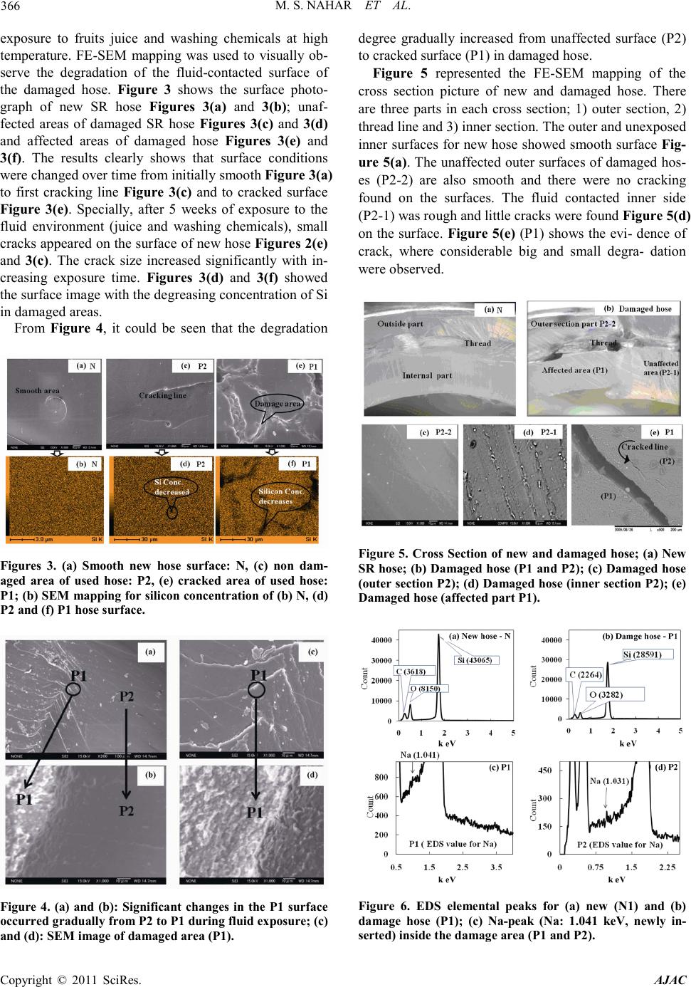
surfaces was estimated to be 0.009 and 0.07(b) -
0.184(c) respectively. These facts would indicate that
sodium, which was inserted by chemical reaction
during the hose washing process with NaOH fol-
lowed, remained inside the silicon backbone, there-
fore, incorporation of Na into the P1 and P2 surface
was clear.
UV-Visible spectroscopy result shows the presence of
leached Si in hose washing chemicals (2% NaOH, 1.5
HNO3).
Therefore, silicon hose were degraded, judged by sili-
con loss and Na insertion into silicon rubber backbone
occurred by hose washing process
5. Acknowledgements
This research was carried out with the financial support
of Scientific Research from the Ministry of Education,
Culture, Sports, Science and Technology of Japan under
grant numbers 16681004 and 19310007. We thank our
laboratory M. Sc. student Kyohei Matsumoto for his
technical assistance.
5. Referen ces
[1] S. J. Clarson and J. A. Semlyen, “Siloxane Polymers,
P TR-Prentice Hall, Englewood Cliffs, 1993.
[2] C. J. Lammi and D. A. Lados, “Effects of Residual Str-
esses on Fatigue Crack Growth Behavior of Structural
Materials: Analytical Corrections,” International Journal
of Fatigue, Vo l . 33, No. 7, 20 11 , pp. 85 8-867.
doi:10.1016/j.ijfatigue.2011.01.019
[3] M. Schulze, T. Kn ori, A. Schnei der and E. Gu lz ow, “ De-
gradation of Sealings for PEFC Test Cells during Fuel
Cell Operation,” Journal of Power Sources, Vol. 127, No.
1-2, 2004, pp. 222-229.
doi:10.1016/j.jpowsour.2003.09.017
[4] B. K. Deka and T. K. Maji, Study on the Properties of
Nanocomposite based on High Density Polyethylene,
Polypropylene, Polyvinyl Chloride and Wood,” Compo-
sites Part A: Applied Science and Manufacturing, Vol.
42, No. 6, 2011, pp. 686-693.
doi:10.1016/j.compositesa.2011.02.009
[5] L. X. Zhang, S. Y. He, Z. Xu and Q. Wei, “Damage Ef-
fects and Mechanisms of Proton Irradiation on Methyl
Silicone Rubber,” Material Chemistry and Physics, Vol.
83, No. 2-3, 2004, pp. 255-259.
doi:10.1016/j.matchemphys.2003.09.043
[6] Y. Zhu, K. Haji, M. Otsubo and C. Honda, “Surface De-
gradation of Silicone Rubber Exposed to Corona
Discharge,” IEEE Transations on Plasma Science, Vol.
34, No. 4, 20 06, pp. 1094-1098.
doi:10.1109/TPS.2006.876498
[7] M. Patel, A. R. Skinner an d R. S. Maxwell, “Sensitivity
of Condensation Cured Polysiloxane Rubbers to Sealed
and Open-to Air Thermal Ageing Regimes,” Polymer
Testing, Vol. 24, No. 5, 2005, pp. 663-668.
doi:10.1016/j.polymertesting.2005.03.013
[8] L. Meunier, G. Chagnon, D. Favier, L. Orgéas and P.
Vacher, “Mechanical Experimental Characterisation and
Numerical Modelling of an Unfilled Silicone Rubber,
Polymer Testin g, Vol. 27, No. 6, 200 8, pp . 765-777.
doi:10.1016/j.polymertesting.2008.05.011
[9] M. Ehsani, H. Borsi, E. Gockenback, G. R. Bakhshandeh
and J. Morshedian, “Modified Silicone Rubber for Use as
High Voltage Outdoor Insulators,” Advances in Polymer
Technology, Vol. 24, No. 1, 2005, pp. 51-61.
doi:10.1002/adv.20027
[10] A. Ghanbari-Siahkali, S. Mitra, P. Kingshott, K. Almdal,
C. Bloch and H. K. Rehmeier, “Investigation of the Hy-
drothermal Stability of Cross Linked Liquid Silicon
Rubber (LCR),” Pol ymer Degradation and Stability, Vol.
90, No. 3, 20 05, pp. 4711-480.
[11] A. N. Chaudhry and N. C. Billingham, “Characterization
and Oxidative Degradation of a Room-Temperature Vul-
canized Poly (Dimethylsiloxane) Rubber,” Polymer De-
gradation and Stability, Vol. 73, No. 3, 2001, pp.
505-510. doi:10.1016/S0141-3910(01)00139-2
[12] B. H. Youn and C. S. Huh, “Surface Degradation of HTV
Silicone Rubber and EPDM Used for Outdoor Insulators
under Accelerated Ultraviolet Weathering Condition,”
IEEE Transactions on Dielectrics and Electrical Insula-
tion, Vol. 12, No. 5, 20 05, pp. 10 15-1024.
doi:10.1109/TDEI.2005.1522194
[13] H. Liu, G. Cash, D. Birtwhistle and G. George,Charac-
terizati on of a Severely Degraded Silicone Elastomer HV
Insulator-an Aid to Development of Lifetime Assessment
Techniques,” IEEE Transactions on Dielectrics and
Electrical Insulation, Vol. 12, No. 3, 2005, pp.
478-486. doi:10.1109/TDEI.2005.1453452
[14] T. G. Gustavsson, S. M. Gubanski, H. Hillborg, S. Kar-
lsson and U. W. Gedde, “Ageing of Silicone Rubber Ma-
terials under AC and DC Voltages in a Coastal Environ-
ment,” IEEE Transaction on Dielectrics and Electrical
Insulation, Vol . 8, No. 6, 2001, pp. 1029-1039.
doi:10.1109/94.971462
[15] D. Graiver, K. W. Farminer and R. Narayan, A Review
of the Fate and Effects of Silicones in the Environment,”
Journal of Polymers and the Environment, Vol. 11, No.
4, 2003, pp. 129-136. doi:10.1023/A:1026056129717
[16] J. Tan, Y. J. Chao, J. W. Van Zee and W. K. Lee, “De-
gradation of Elastomeric Gasket Materials in PEM Fuel
Cells,” Materials Science and Engineering A, Vol. 445-
446, 2007, pp. 669-675.
doi:10.1016/j.msea.2006.09.098
[17] M. Di, S. He, R. Li and D.-Z. Yang, “Radiation Effect of
150˚keV Protons on Methyl Silicone Rubber Reinforced
with MQ Silicone Resin,” Nuclear Instruments and Meth-
ods in Physics Research Section B: Beam Interactions
with Materials and Atoms, Vol. 248, No. 1, 2006, pp.
31-36. doi:10.1016/j.nimb.2006.02.017
[18] N. Yoshimura, S. Kumagai and S. Nishimura, “Electrical
and Environmental Aging of Silicone Rubber Used in
M. S. NAH AR ET AL.
Copyright © 2011 SciRes. AJAC
370
Outdoor Insulation,” IEEE Transactions on Dielectrics
and Electrical Insulation, Vol. 6, No. 5, 1999, pp. 632-
650. doi:10.1109/94.798120
[19] Q. Xu, M. Pang, L. Zhu, Y. Zhang and S. Feng, Me-
chanical Properties of Silicone Rubber Composed of Di-
verse Vinyl Content Silicone Gums Blending,Materials
& D esign , Vo l. 31, No. 9, 2010, pp. 4083-4087.
doi:10.1016/j.matdes.2010.04.052
[20] H. Fink, U. Panne, M. Theisen, R. Niessner, T. Probst
and X. Lin, “Determination of Metal Additives and Bro-
mine in Recycled Thermoplasts from Electronic Waste by
TXRF Analysis Fresenius,” Journal of Analytical Chem-
istry, Vol. 368, 2000, pp. 235-239.
[21] U. Metz, P. Hoffmann, S. Weinbruch and H. M. Ortner,
“A Comparison of X-Ray Fluorescence Spectrometric
(XRF) Techniques for the Determination of Metal Traces,
Especially in Plastics,” Mikrochimica Acta, Vol. 117, No.
1-2, 1994, pp. 95-108. doi:10.1007/BF01243020
[22] V. P . Mar tinez, F . B. Reig, J. V. Gimeno Adelantado and
M. T. Doménech Carb ó, “M ulti-Elemental Determination
of Heavy Metals using X-Ray Fluorescence after De-
struction of the Polymer by Molten Sodium Hydroxide
Fresenius,” Journal of Analytical Chemistry, Vol. 342,
1992, pp.586-590.
[23] M. S. Nahar and J. Zhang, “Influence of Biogeochemi-
cal Qualities of Shizuoka Water on the Degradation of
PVC Shower Hose,Journal of Environmental Pro t ec -
tion, No. 2, 2011, pp. 204-212.
doi:10.4236/jep.2011.22024
[24] I. Stevenson, L. David, C. Gauthier, L. Arambourg, J.
Davenas and G. Vigier, “Influence of SiO2 Fillers on the
Irradiation Ageing of Silicone Rubbers,” Polymer, Vol.
42, No. 22 , 2001, p p. 9287-9292.
doi:10.1016/S0032-3861(01)00470-0
[25] F. G. A. Stone and W. A. G. Graham, Inorganic Poly-
mers,Academic Press, New York, 1992.
[26] W. Huang, Y. Ikeda and A. Oku,Recovery of Mono-
mers and Fillers from High-Temperature-Vulcanized Sili-
cone Rubbers-Combined Effects of Solvent, Base and
Fillers,” Polymer, Vol. 43, No. 26, 2002, pp. 7295-7300.
doi:10.1016/S0032-3861(02)00713-9