 Journal of Power and Energy Engineering, 2016, 4, 19-26 Published Online February 2016 in SciRes. http://www . scirp.org/journal/jpee http://dx.doi.org/10.4236/jpee.2016.42003 How to cite this paper: Shi, S., Xiao, J., Liu, S., Tu, L.M., Cao, Q., Liang, Y., Zhang, G.Y. and Mao , C.X. (2016) A Scheme of Dynamic Voltage Restorer to Improve Power Quality in Large Scale Industrial Enterprises. Journal of Power and Energy Engineering, 4, 19-26. http://dx.doi.org/10.4236/jpee.2016.42003 A Scheme of Dynamic Voltage Restorer to Improve Power Quality in Large Scale Industrial Enterprises Shan Shi1, Jun Xiao2, Shu Liu1, Liming Tu1, Qin Cao1, Yu Liang2, Gaoyan Zhang2, Chengxiong Mao2 1Beijing Sifang Automation Co., Ltd., Beijing 100085, China 2School of Electrical and Electronic Engineering, Huazhong University of Science and Technology, Wuhan 430074, China Received 9 November 2015; accepted 15 February 2016; published 18 February 2016 Abstract Loads in large scale industrial enterprises are always various and complex, causing insecure pow- er quality. Meanwhile, some sensitive loads or precise instruments demand for high power quality. When voltage flicker or harmonics occurs, dynamic voltage restorer (DVR) can be used to stabilize the load-side voltage, which is a good manner of improving power quality. The paper explains the load demand in large scale industrial enterprises, analyzes several common voltage compensation scheme of DVR, and comes up with another voltage compensation scheme of DVR applied for double power supply with double load. A Simulink model according to the new scheme is also built in MATLAB/Simulink to test its performance. Simulation results show that the proposed scheme can guarantee the load-side voltage stability, which is an effective scheme for managing power quality. Keywords Power Quality, Large Scale Enterprises, Double Power Supply with Double Load, DVR Compensation Scheme 1. Introduction Large scale industrial enterprises, electricity consumption of which accounts for 85% of total consumption in the whole country, are a major part of power distribution system (HUANG. 2011) [1] and demand for harsher power quality than normal users (Danie l, J. Love. 1994) [2]. In all kinds of power quality matter, voltage flicker occurs frequently and seriously impacts the normal work of load. Dynamic voltage restorer (DVR) is a kind of controlled voltage source device, which is able to compensate the power needed. It has high efficiency, and costs less than other devices such as uninterruptible power supply, constant voltage transformer and motor-generator. Besides the basic voltage compensation function, DVR also can achieve the harmonics compensation and reactive power compensation function. It is the most effective and  S. Shi et al. popular power electronic equipment solving the problem of voltage (HAN et al., 2003) [3]. Therefore, DVR can not only improve power supply reliability, but also enhance load-side power quality. At present, there are three types of mostly studied DVR (Nielsen, G.J. & Blaabjerg, F., 2005) [4]. DVR with DC capacitor is supposed to compensate reactive power only, otherwise, its DC voltage will decrease seriously as active power consuming. This method doesn’t perform well in voltage compensation time and degree (Jothi- basu, S. & Mishra, K. M. 2014) [5]. DVR with energy storage system often chooses storage battery, supercon- ducting magnetic energy storage or flywheel energy storage as energy source (Ramachandaramurthy, V.K. et al. 2002) (LIU. et al. 2004) (de Andrade R. et al. 2005) [6]-[8]. By this means, DVR is able to compensate reactive power as well as active power. However, it exits some problems using no matter which storage system, for ex- ample, cost will increase and control will be more complex. In DVR with rectifying system, in order to complete long -time compensation, DC capacitor is link to power supply side or load side through rectifying circuit. When voltage fault occurs in supply side, it is so difficult to maintain a constant DC voltage in DC part, and chances are that harmonics voltage or overvoltage will be introduced to DVR. Besides, rectifying circuit cannot obtain energy through power grid if grid voltage drops seriously, and chances are that more serious voltage drop will occur (YANG et al., 2004.) (YIN & ZHI, 2005) [9] [10]. This paper comes up with a new voltage compensation scheme of DVR applied for double power supply with double load, which has the merits of both DVR with energy storage system and DVR with rectifying system. Simulink model of common scheme and model according to the new scheme are all built in MATLAB/Simulink, so that we could compare the merits or demerits between them. Simulation results show that the proposed scheme can guarantee the load-side voltage stability, which is an effective scheme for managing power quality. 2. The Requirement of Power Quality in Large Scale Industrial Enterprises With the continuous development of science and technology, contradictions between sensitive loads and power quality polluting equipment in large scale industrial enterprises become more and more prominent. On the one hand, there are often a large number of imported equipment and precision instruments in large scale industrial enterprises, which demand high on power supply reliability and power quality (HUANG, 2012) [11]. If grid voltage is not stable, such as frequency fluctuates, waveform changes or short time power outages, it is likely to have a great impact on the production process and product quality. For example, some devices with sensitive re- lay protection maybe automatically jump to open, making the whole line in outage and resulting in huge eco- nomic losses. In recent years, voltage rising and dropping drastically or shot time power outages have become the most prominent problem, which influence the safe operation of the load in large scale industrial enterprises. If the problem is not serious, it maybe only make production line stop and production scrap; if the problem is se- rious, it will even cause production accident or human casualty (GUAN, 2012) [12]. On the other hand, the loads in large scale industrial enterprises always have outstanding characteristics such as nonlinear, impact or intermittent, and the start or stop of a single load will has much influence on power grid (FU & WEI, 2011) [13]. Taking the iron and steel enterprises as an example, electric arc furnace is a typical nonlinear load, while rotat- ing mill is a typical impact load, and both of them have a single capacity of MW level (SUN & QIN, 2008) [14]. Electric arc furnace is a three-phase asymmetric load in melting period, while active and reactive power random change, which can cause voltage flicker fluctuations and negative sequence current and harmonic, etc. When ro- tating mill is in biting course, motor current is very big, but the active power is less than the rated active power, while the reactive power is much more than the rated reactive power. At this time, the rotating mill has the worst hit reactive power and lowest power factor to power grid. In general, in all kinds of power quality problems, the occurred frequency of voltage flicker is the highest and its influence is the most serious. At present in industrialized countries, voltage flicker has increased to one of the most important power quality problems. According to reports, voltage flicker accounts for over 80% of all the complaints from customs about power quality problems, while voltage harmonics accounts for only less than 20% (YUAN, 2005) [15]. The effect of voltage flicker is so great because many industrial processes in large scale industrial enterprises are sensitive to it. These industrial processes involve many fields including semiconductor, papermaking, plastic, petrochemical, textile, glass and rubber, etc. Economic losses caused by voltage flicker includ e not only losses of product quality and production line stoppage, but also the costs on the whole produc- tion line start. According to reports, as a result of the four cycle of voltage drop, an enterprises takes 72 minutes to restore production line of work, causing a loss of 700 thousand dollars. Therefore, how to improve power supply reliability and power quality in large scale industrial enterprises is a problem to be solved.  S. Shi et al. 3. Scheme of DVR Applied for Double Power Supply w ith Double Load DVR, which has very high performance value ratio, is a controlled voltage source device used to solve power quality problems such as voltage flicker and harmonics. It is set between load and power supply (Figure 1) to compensate the load side voltage when the power failure occurs or power supply side has temporarily voltage flicker or harmonics. In large scale industrial enterprises, power supply adopts double standby power supply system, such as unin- terruptible power supply, emergency power supply, bus-bar automatic transfer switch, system for the static switch and automatically transfer switch, against critical load. Two way power supply are spare to each other through the DVR scheme applied for double power supply with double load. If one way power supply failure or voltage drop occurs, DVR can obtain power from the other way. Compensation voltage is generated by the PWM inverter, and coupled to the circuit through the transformer. Large scale industrial enterprises often appear three-phase asymmetric loads, single-phase inverter has been adopted so that three phase can be controlled independently. In this model, three phase are in equal status, therefore, we just need to analyze one phase, for example, phase A, and the other two phase is similar. In order to make the paper simpler, only one-phase structure will be analyzed in the latter part of this paper. The location of DVR (phase A) is shown as Figure 2. Although the voltage flicker or harmonics occurs frequently in large scale industrial enterprises, the likelihood that two way power supply fail at the same time is much lower than just one way power supply. When source S1 has voltage drop, source S2 can still provide normal power supply. The single-phase inverter in the way of S1 obtains the power from source S2 to compensate voltage, so that the load side voltage of LD1 can maintain con- stant. This scheme doesn’t need any more storage device, and is able to solve the problem of the DVR with rectify- ing system: when voltage drops deeply, it can’t compensate the voltage very well. Besides, there are always several power supply with several load in the large scale industrial enterprises, the scheme can be generalized in the situation of several power supply with several load. For example, if there are m way power supply with m way load, when source S1 has voltage drop, the other m − 1 way power supply will provide energy for the sin- gle-phase inverter in the way of S1, in order to make the voltage stable in the way of S1. Figur e 1. DVR installation location in the circuit. Figure 2. Scheme of DVR applied for double power supply with double load. DVR senstive lo ad normal lo ad single-phase invertersingle-phase inverter  S. Shi et al. 4. The Topological Structure and Unit Design of DVR 4.1. Design of Inverter Unit As mentioned earlier, large scale industrial enterprises often appear three-phase asymmetric loads. In three sin- gle-phase DVR with full-bridge configuration, each phase is independent of each other. Although a greater number of switching devices have been used and the cost increases as well, sub-phase control can be achieved and zero sequence voltage can be compensated in this way. In this way, DVR is more flexible and suitable for the extensive use of three-phase grid with a four-wire system structure in large scale industrial enterprises. The structure of single-phase inverter is shown in Figure 3. The state space model of the structure is: L ff Ldcc c f Lc di LR iSuv dt dv C ii dt +=− = − (1) where S = switching function. Inverter has a variety of control and modeling methods, control core is the on-off control of four IGBT in sin- gle-phase H-bridge circuit (Wang, B. et al. 2006) [16]. Considering the voltage and current double loop control has good static and dynamic response performance, and is able to satisfy the need of DVR’s rapidly response to the control system, double closed-loop control scheme based on the DVR output voltage and output filtering in- ductance current have been adopted, as shown in Figure 4. The Figure 4 shows that the DVR voltage instruction signal vc-ref is compared with actual offset voltage vc, the difference of them is the error voltage signal, which produces the inductance current instruction signal iL-ref through a PI regulator. The inductance current instruction signal iL-ref is compared with inductance current feed- back signal iL, the error signal between them produces the on-off signal S through another PI regulator. In this double closed-loop control scheme, the current inner loop adopts a PI current regulator. The proportion cycle of curr ent regulator is used to increase the damping coefficient of the inverter, make the whole system work stea- dily, and ensure the strong robustness, while the integral cycle is used to reduce the steady-state error of current loop. The voltage outer loop adopts a PI voltage regulator as well, which is used to make the instantaneous out- put voltage waveform track to a given value. As a disturbance signal of inverter, the DVR compensating current ic is out of the current loop, so the control performance of the system for load disturbance is poor. In order to eliminate the load disturbance, the compen- sation current ic and voltage vc are introduced as feed forward control signal, reducing the PI mediator’s media- tion extent and the influence of external disturbance on the system control performance. Figure 3. Structure of single-phase inverter. Figure 4. Double closed-loop control scheme.  S. Shi et al. 4.2. Design of Detection Unit The detection unit is supposed to accurately and rapidly detect the voltage flicker amplitude, dropping start-stop time, phase jump angle and other relevant parameters. Generally, the d-q transformation method based on in- stantaneous voltage is common to use: the instantaneous voltage of positive sequence component is transferred to the DC component of d-q coordinate system, while negative sequence component is transferred to the double frequency component. After filtering processing, only positive sequence component is left. In the single-phase system, d-q transformation can’t be directly applied. Two-phase static coordinate system is supposed to be built according to single-phase voltage, then transferring it to the two-phase rotating coordi- nate system. It will have a large delay when built by 90-degrees-lag method, and will have an overshoot when built by derivative method. Small angle method can coordinate the contradiction between delay and overshoot. The method is constructed as follows. Take the single-phase voltage as β-axis voltage, and obtain the α-axis voltage by the expression sin( ) sin( ) UU t UU t β β ωϕ ω ϕθ = + ′= +− (2) Then, cos()/tan/ sinUU tUU α ββ ωϕθ θ ′ = +=− (3) According to the transformation formula: cos sin sin cos d q UU tt UU tt α β ωω ωω = − (4) where Ud = single -phase instantaneous voltage amplitude. 5. Rectifier DVR Simulation Results DVR with rectifying system obtains power from power supply side or load side, but many problems will occur when voltage drops seriously, even deteriorating power quality. The system parameters of simulation are shown in Table 1. The simulation system is shown in Figure 5. Figure 5. DVR with rectifying system. Table 1. System parameters of simulation in rectifier DVR. Parameters Value Source voltage Vs 220 V Load R 1 Ω One-phase load capacity S 4.84 kVA Transformer ratio K 1 DC voltage Vdc 400 V Filtering inductance L 4 mH Filtering capacitor C 60 μF single-phase invertersingle-phase inverter  S. Shi et al. In order to verify that the DVR with rectifying system may not work properly when the magnitude of the vol- tage drops seriousl y, the paper selects two conditions to simulate, one is the voltage drop to 30% of the rated values, another is 70% of the rated values. The simulation results are shown in Figure 6. According to the simulation results, when amplitude of voltage drop is smaller, the DVR can be used to com- pensate the voltage drop, and load side voltage can be stabilize to the rated value. But when amplitude of voltage drops seriousl y, due to the DC side of DVR obtains energy from the supply side, DC voltage will decline, the DVR cannot fully compensate for voltage drop, which causes voltage distortion. 6. Double Power Supply with Double Load Compensation Scheme Simulation Results When the double power obtain energy from each other, the possibility that two power supplies fail to work at the same time is much lower than that just one power supply is unable to work. The system parameters of simu l a- tion are shown in Table 2. The simulation system is shown in Figure 2. In this simulation, the voltage amplitude of source S1 drops to 30% of the rated values, while another source S2 works normally, the results of simulation are shown in Figure 7. (a) (b) (c) (d) (e) (f) Figure 6. Simulation results. (a) Power voltage, load voltage and compensation voltage waveforms when the voltage drop to 30% of the rated values; (b) voltage and current waveforms in load side when the voltage drop to 30% of the rated val- ues; ( c) voltage waveform in DC side of DVR when the voltage drop to 30% of the rated values; (d) power voltage, load voltage and compensation voltage waveforms when the voltage drop to 70% of the rated values; (e) voltage and current waveforms in load side when the voltage drop to 70% of the rated values; (f) voltage waveform in DC side of DVR when the voltage drop to 70% of the rated values. 0.05 0.1 0.15 0.2 0.25 -400 -200 0 200 400 t(s) Us(V), Uo(V) and Uc(V) Us Uo Uc 0.05 0.1 0.15 0.2 0.25 -400 -200 0 200 400 t(s) Uo(V) and Io(A) Uo Io 00.1 0.2 0.3 0.4 0.5 0 100 200 300 400 500 t(s) Udc(V) Udc 0.05 0.1 0.15 0.2 0.25 -400 -200 0 200 400 t(s) Us(V), Uo(V) and Uc(V) Us Uc Uo 0.05 0.1 0.150.2 0.25 -400 -200 0 200 400 t(s) Uo(V) and Io(A) UoIo 00.10.2 0.30.4 0.5 0 100 200 300 400 500 t(s) Udc(V) Udc 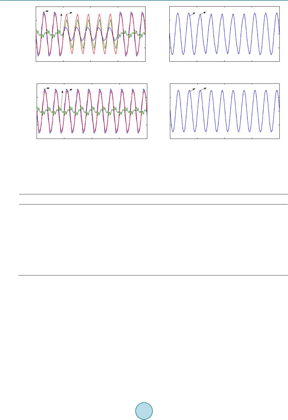 S. Shi et al. (a) (b) (c) (d) Figure 7. Simulation results of double power supply with double load. (a) Power voltage, load voltage and compensation voltage waveforms of source S1; (b) voltage and current waveforms of source S1 in load side; (c) power voltage, load voltage and compensation voltage waveforms of source S2; (d) voltage and current waveforms of source S2 in load side. Table 2. System parameters of simulation in new compensation scheme. Parameters Value Source voltage Us 220 V Load R 1 Ω One-phase load capacity S 4.84 kVA Transformer ratio K 1 DC voltage Udc 400 V Filtering inductance Lf 4 mH Filtering capacitor Cf 60 μF 7. Conclusions Through theoretical analysis and simulation studies, we can see that, for various and complex loads in large scale industrial enterprises, the proposed double power supply with double load DVR compensation scheme can well solve the voltage drop problem to guarantee load’s normal work. This scheme has no storage energy system, so that it costs less than DVR with energy storage system; has two way supply sources spare to each other, so that it performs better than normal DVR with rectifying system. Therefore, it’s a simple and economical scheme and significant for large industrial enterprises to improve power supply reliability and enhance load-side power quality. References [1] Huang, X.-Y. (2011 ) Dynamic Voltage Restorer Based on Super-Capaci tor . M.S. Dissertation, Huazhong University of Science & Technology, Wuhan. [2] Lo ve, D.J. (1994) Reliability of Utility Supply Configurations for Industrial Power Sys tem s. IEEE Transaction on In- 0.05 0.1 0.15 0.2 0.25 -400 -200 0 200 400 t(s) Us(V), Uo(V) and Uc(V) Uc Uo Us 0.05 0.1 0.150.2 0.25 -400 -200 0 200 400 t(s) Uo(V) and Io(A) Uo Io 0.05 0.1 0.150.2 0.25 -400 -200 0 200 400 t(s) Us(V), Uo(V) and Uc(V) Us Uc Uo 0.05 0.1 0.15 0.2 0.25 -400 -200 0 200 400 t(s) Uo(V) and Io(A) UoIo  S. Shi et al. dustry Applications, 30, 1303-1308 . http://dx.doi.org/10.1109/28.315243 [3] Han , Y.-D., Jiang, Q.-R., Le, J. and Yan , G.-G. (2003) Modern Electric Power and FACTS&DFACTS. Electrical Equipment, 4, 5-10. [4] Niel sen, J.G. and Blaabjerg, F. (2005) A Detailed Comparison of System Topologies for Dynamic Voltage Restorers. IEEE Transactions on Industry Applications, 41, 1272-1280 . http://dx.doi.org/10.1109/TIA.2005.855045 [5] Jothibasu, S. and Mi shr a , M.K. (2014) A Control Scheme for Storageless DVR Based on Characterization of Voltage Sags. IEEE Transactions on Power Delivery, 29, 2261-2269 . http://dx.doi.org/10.1109/TPWRD.2014.2316598 [6] Ramachandaramurthy, V.K., Fitzer, C., Arulampalam, A., Zhan, C., Barn es, M. and Jenkins, N. (2002) Control of a Battery Supported Dynamic Voltage Restorer. In IEE Proceedings-Generation, Transmission and Distribution Meeting, Manch ester, 53 3-542. [7] Li u , X., Zhu, X.-G., Zhu, X. and Jiang, X.-H. (2004) Compensation of Instantaneous Voltage Drop Based on Super- conducting Energy Storage. Automation of Electric Power Systems, 28, 40-44. [8] de Andrade, R., Ferreira, A.C., Sotelo, G.G. , Silva Neto, J.L., Roli m, L.G. B. , Suemitsu, W.I., Bessa, M.F., Stephan, R.M. and Nicolsky, R. (2005) Voltage Sags Compensation Using a Superconducting Flywheel Energy Storage System. IEEE Transaction on Applied Superconductivity, 15, 2265-2268 . http://dx.doi.org/10.1109/TASC.2005.849627 [9] Yang, C., Han, Y.-D., and Ma, W.-X. (2004) Research of Single-phase Series Power Quality Compensator Controller. Automation of Electric Power Systems, 26, 45-48. [10] Yin, Z.-D. and Zhi, L.-X. (2005) Energy Extraction Method of Dynamic Voltage Restorer Based on High-Frequency Rectifier. Power Electronics, 39, 67-69. [11] Huang, L. (2012) Research on Voltage Sag Influence the Sensitive Load and Control Measures, M.S. Dissertation, Guangdong University of Technology, Guangzhou. [12] Gu an, X.-B. (20 12 ) Research on Dynamic Voltage Restorer, M.S. Dissertation, Huazhong University of Science & Technology, Chengdu. [13] Fu, Y.-S. and Wei , M.-G. (2011) Power Quality Features of Different Industry Loads. Power Capacitor & Reactive Power Compensation, 32, 11-17. [14] Sun, W. and Qin , L.-J. (2008) Power Quality Analysis and Control in Iron and Steel Enterprises. Electrical Equipment, 9, 68-71. [15] Yuan , C. (2005) Research for Real-time Detection of Characteristics of Voltage Sag and Compensation Method of Dynamic Voltage Restorer, M.S. Dissertation, Sichuan University, China. [16] Wan g, B.S. Ven kataramanan , G. and Illindala, M. (2006 ) Operation and Control of a Dynamic Voltage Restorer Using Transformer Coupled H-Bridge Converters. IEEE Transactions on Power Electronics, 21, 1053-10 61 . http://dx.doi.org/10.1109/TPEL.2006.876836
|