 Journal of Power and Energy Engineering, 2016, 4, 13-18 Published Online February 2016 in SciRes. http://ww w.scirp.org/jo urnal/jpee http://dx.doi.org/10.4236/jpee.2016.42002 How to cite this paper: Ni, P.H., Wang, W. and Wei, P (2016) Design of On-Line Monitoring System for UHVDC Earth Elec- trode. Journal of Power and Energy Engineering, 4, 13-18. http://dx.doi.org/10.4236/jpee.2016.42002 Design of On-Line Monitoring System for UHVDC Earth Electrode Pinghao Ni1, Wei Wang1, Peng Wei2 1School of Electrical Engineering, Beijing Jiaotong University, Beijing, China 2Ningxia Electric Power Maintenance Company, Ningxia, China Received 9 November 2015; accepted 15 February 2016; published 18 February 2016 Abstract At present the detecting of ultra high voltag e direct current (UHVDC) earth electrode frequently uses manual inspection. This method can' t get the real-time operational data of the earth elec- trodes, and meanwhile, the labor cost is very high. In order to satisfy the security needs of UHVDC, this paper designs an on-line monitoring system for UHVDC earth electrode. By 3G wireless com- municatio n-techn olog ies, the system can monitor remotely many kinds of data such as the value of the grounding current, water level of the observation well, soil temperature and humidity near the earth electrode, the micro-climate around the earth electrode site, video data, etc. Through ana- lyzing the datum, the system has broad prospect on fault detect ion and life evaluation of the UHVDC earth electrode. Keywords UHVDC , Earth Electrode, On-Line Monitoring, 3G 1. Introduction Up to now, China has completed Xiangjiaba-Shanghai, Jinping-Sunan, So uth of Hami-East of Zhengzhou, Left bank of Xiluodu-Jinhua in Zhejiang UHVDC transmission projects. Direct cur rent (DC) converter station is an important part of DC power transmission system, the earth electrode play a crucial role: the first is to provide a path of DC current for the system over a long period of time and improve the reliability of the system; the second is to clampe the neutral point potential of converter Station (rectifier valve) and avoid the unbalance vol- tage to the ground of the two poles, it could damage the equipment (Gao Xiaogang et al. 2012) [1]. Because the operation time of UHVDC transmission is shorter, t he operation datum are less, the on-line monitoring system for UHVDC earth electrode is rarely used, the operation data of UHVDC earth electrode basically rely on ma- nual collection, the degree of automation is low, it can not meet the rapid development of UHVDC transmission system, so the on-line monitoring system for UHVDC earth electrode has very important realistic significance. The earth electrode is located in the field, so the monitoring data need long-distance transmission, thus the communication of on-line monitoring system for UHVDC earth electrode has special requirements. In this paper, the 3rd Generation (3G) wireless communication technology is used in the on-line monitoring system, compared with the previous design scheme based on global system for mobile co mmunication (GSM) and general packet 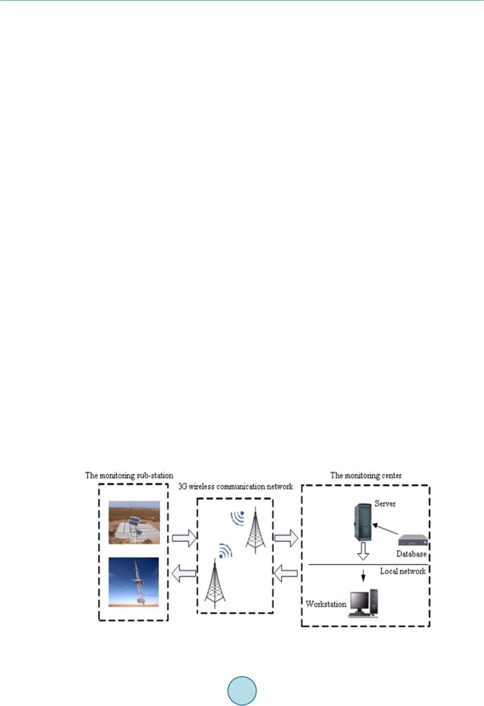 P. H. Ni et al. radio service (GPRS) wireless communication technology (Chen Lin et al. 2012) [2], this system has greatly improved the speed and the reliability of monitoring data transmission, and the video data also can be transmit- ted in real time. Therefore, the system can monitor remotely many kinds of data collected by different sensors such as the value of the grounding current, water level of the observation well, soil temperature and humidity near the earth electrode, the micro-climate around the earth electrode site and video data. By analyzing the data received. The system can be used to diagnose the operation state and evaluate the life of the earth electrode. 2. The Structure of UHVDC Earth Electrode System The UHVDC earth electrode system is mainly composed of earth electrode line, feeder cable and the earth elec- trode. The earth electrode line connect the neutral bus of converter station and the feeder cable which is placed overhead or underground; the feeder cable is connected to the earth electrode and earth electrode line; the earth electrode is placed in the ground which constitutes a low resistance path between DC circuit and the earth, it could be a group of conductors or activity backfill materials which can be sustained by a constant current fo r a certain period of time. The UHVDC earth electrodes are mainly in the forms of horizontal ring type, horizontal double ring type, vertical type or deep well type. Usually the materials which can be used as the earth electrode could be carbon steel, copper, graphite, high silicon cast iron, ferrite, etc (Zhu Zhixiang et al. 2012) [3]. The operation of the UHVDC syste m include s three modes, there are double-electro d e-gr ound-re tur n method, single-electrode-ground-return method and single -electrode-conductor-return method. In the double-electrode- ground-return method, the unbalance current in which would be less than 1% rated current flow into the earth in general, it would have no impact on the environment. In the single-electrode-ground-return method or single- electrode-conductor-return method, when one electrode is repairing or out of operation due to a fault, large cur- rent would flow through the earth electrode. At this time there will form a constant electric field near the site of the earth electrode, along with the surface potential rise, step voltage and contact potential being formed, result- ing underground metal structures c orr oding. The most serious situation is: if the neutral points of two alternating curre nt (AC) transformers are connected to the ground and the potential difference of two neutral points is large, it will generate the DC current between two transformers. when the DC current flows through the transformer winding, magnetic flux of DC superimposes AC which will cause DC bias in the transformer (Yu Yang et al. 2010) [4], then in turn it st re ngthens the vibration of the transformer vibration and increases the noise, the trans- former loss and temperature-rise, this will seriously affect the normal operation of the transformer (Yang Yongming et al. 2012) [5], so the on-line monitoring system for UHVDC earth electrode is essential. 3. Desig n of the On-Line Monitoring System 3.1. The Overall Structure of the On-Line Monitoring System The on-line monitoring system for UHVDC earth electrode is composed of monitoring sub-station, 3G wireless communication network and monitoring center, as shown in Figure 1. Fig ure 1. The structure of the on -line monitoring system.  P. H. Ni et al. The monitoring sub-station is installed in the tower near the earth electrode, using solar power-storage battery supply system, it collects and processes the data and real-time video data, all kinds of datum collected by dif- ferent sensors are sent to the monitoring center through 3G wireless communication network. The monitoring center is the core of the system, it receives many kinds of data and stores in the database. By analyzing the mon- itoring data the monitoring center, it can realize the fault diagnosis and life evaluation of UHVDC earth elec- trode, and also provide various application services to customers. It receives ma ny kinds of data and stores in the database, by analyzing the monitoring data the monitoring center can realize the fault diagnosis and life evalua- tion of UHVDC earth electrode, and also provide various application services to customers. 3.2. Design of the Monitoring Sub-Station 3.2.1. The Structure of the Moni to rin g Sub-St ati on The monitoring sub-station consists of microcomputer control system, various sensors(such as DC current sen- sor, water level sensor, soil temperature and humidity sensor), meteorological data acquisition unit (such as wind velocity and direction sensor, atmospheric temperature and humidity sensor), camera, solar power-storage battery supply system, 3G communication module, data transmission control module, etc. as shown in Figure 2. 3.2.2. The Microcomputer Control System The microcomputer control system is designed based on microcomputer PIC16F877A, the system is used for collecting and processing the monitoring data and real-time video data. 3.2.3. Monitoring Data of the System and Sensor The feeder current of earth electrode: The system usually has multiple feeder cables and a plurality of earth electrodes, the system uses the Hall current sensor to collect the current of earth electrode. The soil temperature and humidity near the earth electrode: The system uses soil temperature and humid- ity sensor to collect the soil temperature and humidity. The water level of the observation well: The system uses the water level sensor to collect and monitor the water level of the observation well. The micro-climate around the earth electrode: The system uses the atmospheric temperature and humidity sensor, the wind velocity and direction sensor to collect the data of micro-climate around the earth electrode. The video around the earth electrode: The system uses a high-definition camera to capture video around the earth electrode. 3.2.4. The Solar Power-Storage Battery Supply System The solar power-storage battery supply system adopts the photovoltaic mode, it consists of photovoltaic cell pa- nels, battery and power management module, DC/AC converter, etc. The system can ensure the independent uninterrupted operation in the field. As shown in Fig ur e 3. Fig ure 2. The structure of the monitoring sub-station. 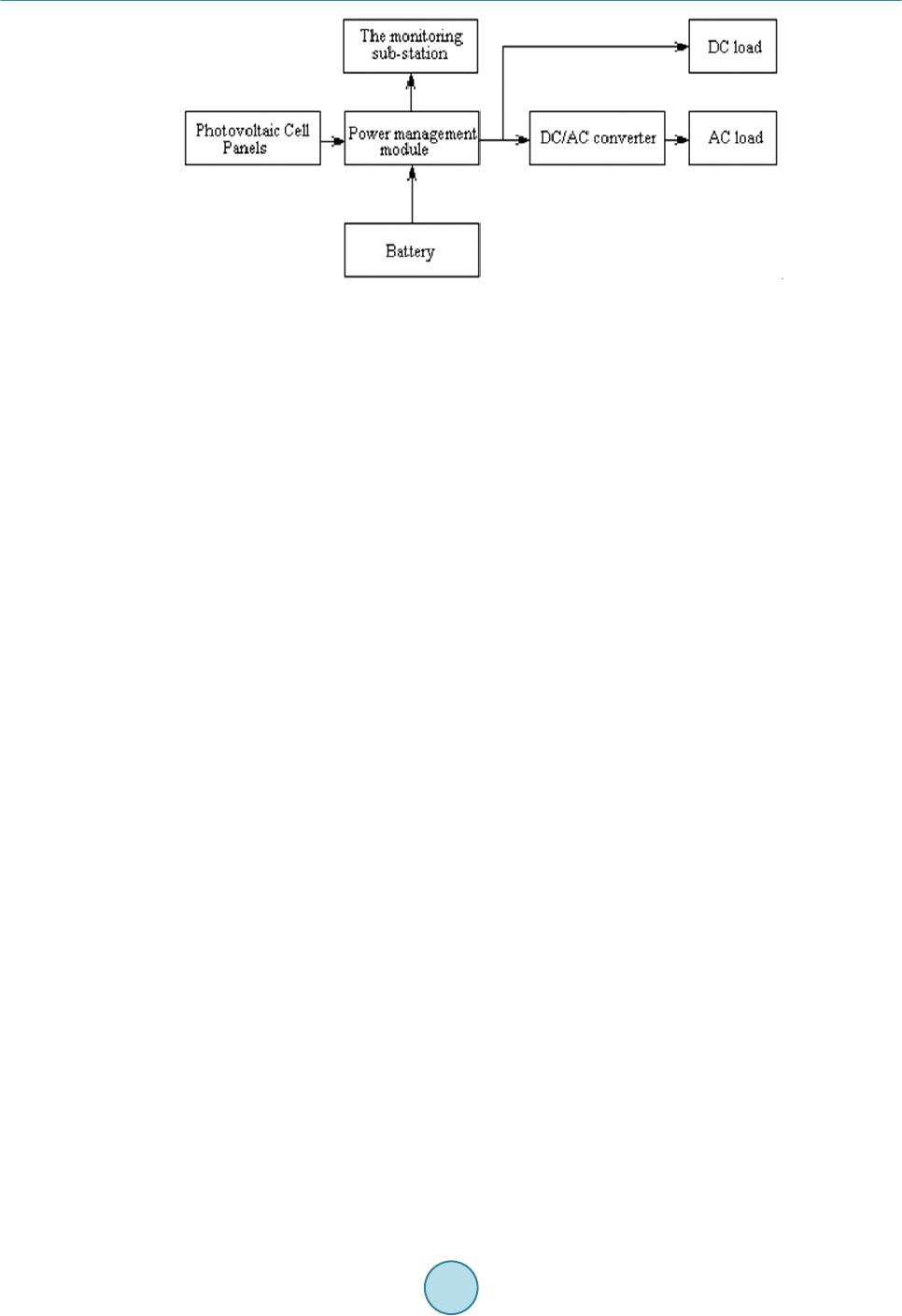 P. H. Ni et al. Fig ure 3. The solar power supply system. 3.2.5. 3G Wireless Communication Module By 3G wireless communication module, the system receives the monitoring data and video data from the moni- toring sub-statio n. The 3G wireless communication adopts the third generation communication technology, it has high speed of data transmission, it can provide worldwide wireless roaming and process images, music, video and other media datum. As a comparison, other means of wireless communication such as GSM or GPRS wireless communica- tion, the data transmission sp eed is slow (Yang Wenyu et al. 2006) [6], the system can’t get clear and fluent video, so the 3G wireless communication technology is used to transmit and receive the video and monitoring information in the on-line monitoring system. Because of the instability of 3G signal in different places and the uncertainty in the location of the monitoring sub-station, The 3G wireless communication module can adapt dif- ferent networks, it can easily switch among the Time Division-Synchronous Code Division Multiple Access (TDSCDMA) of China Mobile, the Code Division Multiple Access (CDMA) of China Telecom and the Wide- band Code Division Multiple Access (WDMA) of China Unicom. 3.2.6. Th e 3G Data Transmission Control Module The data transmission control module is used to control the 3G wireless communication module and the data compresses the monitoring data and video data. The system compresses the monitoring data and the real-time video data respectively, then the two kinds of data packets are loaded into the 3G wireless communication module to realize the combination transmission of monitoring data and video data. The video collection and transmission adopt H.264 video compression algo- rithm, streaming media technology which realize the real-time dynamic image transmission. The monitoring center displays the monitoring data and the real-time video by decoding the data packets. 3.3. The Design of Monitoring Center The monitoring center is composed of four parts, there are the communication server of monitoring system, da- tabase system, the GIS software and client software, the structure of the monitoring center is shown in Figure 4. The main function of the monitoring center are: co mmunica tin g with the monitoring sub-station, storing var- ious monitoring data to the database, the management and analysis of various monitoring information, the diag- nosis of operation state and life evaluation of earth electrode, providing various application service to customers, etc. 3.4. The Diagnosis of O perati o n State and Life Evaluation of Earth Electrode 3.4.1. The Di azgnosis of Earth Electrode O p er ati on S tat e The operation state diagnosis by the feeder current: When the monitoring center receives the feeder cur- rent of the earth electrode, the system can determine the size and the distribution of the grounding current. If the feeder current is too large, it may increase earth electrode corrosion and reduce the life of earth electrode (Lu Jiming et al. 2006) [7]. Under normal circumstances, the feeder current value is directly proportional to the length of earth electrode and basically remains uncha nged . If the difference between the measured value and the 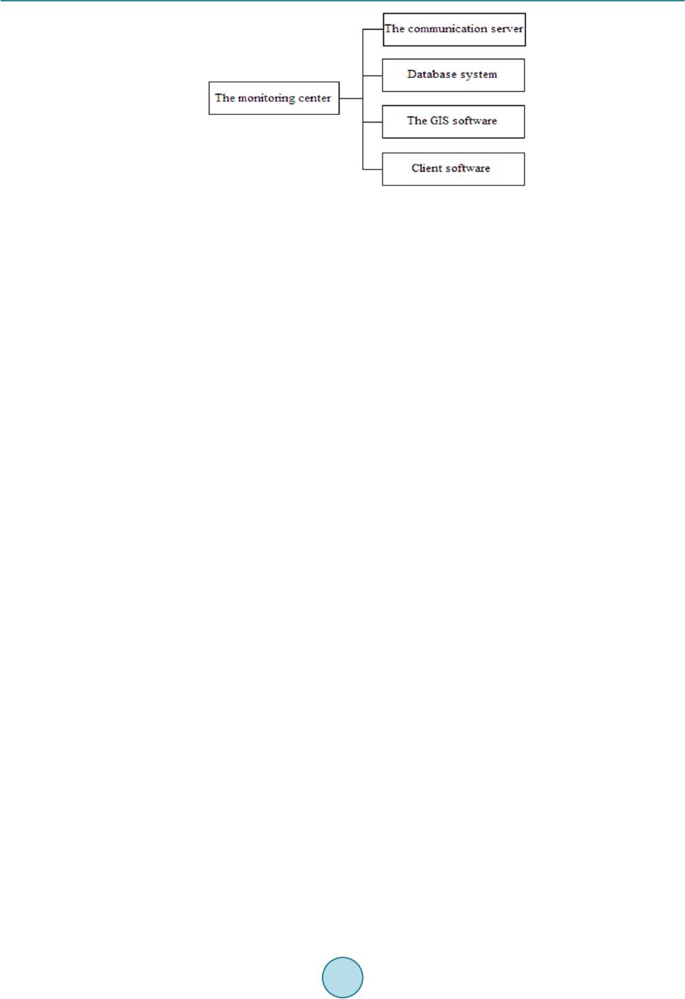 P. H. Ni et al. Fig ure 4. The structure of the monitoring center. reference value is relatively large, then the earth electrode may be severely corroded. And the system will send an alarm signal. The operation state diagnosis by soil temperature and humidity near the earth electrode: When the monitoring center receives the soil temperature and humidity near the earth electrode, the system can grasp the state of the soil around. If the temperature is too high or the humidity is too low, it may increase the soil resistiv- ity and it may affect the distribution of the grounding current, surface potential, step voltage, the heating of the earth electrode, increasing earth electrode corrosion, so in any case the temperature of the earth electrode should not be too high (Sima Wenxia et al. 2012) [8] , if the measured value is higher than the reference value, the sys- tem will send an alarm signal. The operation state diagnosis by the water level of the observation well: When the monitoring center receives the data of water level in the observation well, the system can grasp the drawdown of the water level. If the water level in the well is too low, it will cause earth electrode fault, when the measured value is lower than the reference value, the system will send an alarm signal. The operation state diagnosis by the micro-climate data and video data: When the monitoring center receives the micro-climate data and video data, the system can grasp the impact of the surrounding environment around the earth electrode site in the converter station. The operation state of the earth electrode is closely re- lated to meteorological conditions, the system makes full use of the meteorological data combining with the video data, and masters the operation condition of the earth electrode under complex conditions, especially in the heavy rain, snow, wind and other weather conditions, a large amount of earth electrode operation data can provide the basis for the planning and design of earth electrode in the converter station. 3.4.2. Th e Life Evaluation of Earth Electrode According to the provisions of DLT 437-2012, Technical guide of HVDC earth electrode system in China, the designed life of DC earth electrode should generally be not less than 30 years under the regulation operation mode (Liu Zhenya, 2009) [9 ]. Because the earth electrode corrosion rate is closely related to the grounding cur- rent, the system can roughly infer the corrosion degree of the earth electrode according to current and operating parameters, the system even gives further analysis of the factors affecting the life of the earth electrode, and draws life curve for better maintenance and timely replacement. 4. The Characteristics of This System This system is a remote online integrated monitoring system including on-line monitoring and on-line control- ling which can monitor many operating parameters and video data around the earth electrode site. This system can monitor many kinds of datum collected by different sensors such as the value of the grou n- ding current, water level of the observation well, soil temperature and humidity near the earth electrode, the mi- cro-climate around the earth electrode site. This system can realize the diagnosis of earth electrode operation state and the life evaluation of earth elec- trode. This system can realize combination transmission of monitoring data and video date, it saves transmission way for monitoring data, meanwhile it greatly improve the transmission speed.  P. H. Ni et al. 5. Conclusion This paper designs an on-line monitoring system for UHVDC earth electrode, it can be used in unattended DC converter station, many operating parameters such as the grounding current, water level of the observation well, soil temperature and humidity near the earth electrode, the micro-climate around the earth electrode site, etc are collected. The system realizes the mixed transmission of monitoring data and video data by 3G wireless com- munication with high transmission speed and high image quality. The system can significantly reduce the work- load of UHVDC earth electrode detecting, and realize the diagnosis of earth electrode operation state and the life evaluation of earth electrode, it will be found wide application in the future. References [1] Gao, X.G., Zhou , Y.S. and Wang, Y.F. (2012) Research On the Burial Depths Characteristics of the Annular Groun- ding Electrodes in UHVDC Converter Stations. Insulators and Surge Arresters, 2, 72-76. [2] Chen , L., Wang, H.J. and Wan, Y.L. (2012) Online Monitoring and Communication of High Voltage Electrode Based on GPRS. Industrial Control Computer, 81-82. [3] Zhu, Z.X., Han , Y. and Hui, N. (2012 ) Application and Development of Ground Electrode Materials for HVDC Transmission System. East China Electric Power, 40, 265 -269. [4] Yu, Y., Wei, C. and Zhu, L. (2010) Impact of HVDC ground Electrode Current on Transformers with Different Stru c- tures. Power System Protection and Control, 38, 71-76. [5] Yang, Y.M., Liu, X.M. and Ch en, T. (2012) Impact of Soil Structure Adjacent to Ground Electrodes of UHVDC Power Transmission Lines on DC Bias of Power Transformers. Power System Technology, 36, 26-32. [6] Yang, W.Y., Liu, J. and Wang, J.Y. (2006) On-Line Monitoring System for HVDC System Earth Pole. High Voltage Engineering, 32, 15-17. [7] Lu, J.M., Xiao , D. and Mao, C.X. (2006) Analysis of Effects of DC Earthed Pole on Earth Surface Potential Distribu- tions. High Voltage Engineering, 32, 55-58. [8] Si ma , W.X., Luo, L. and Yuan, T. (2012) Temperature Characteristic of Soil Resistivity and Its Effect on the DC Grounding Electrode Heating. High Voltage Engineering, 38, 1192-1198. [9] Liu, Z.Y. (2009) UHVDC Transmission Theory. China Electric Power Press, Beijing.
|