Paper Menu >>
Journal Menu >>
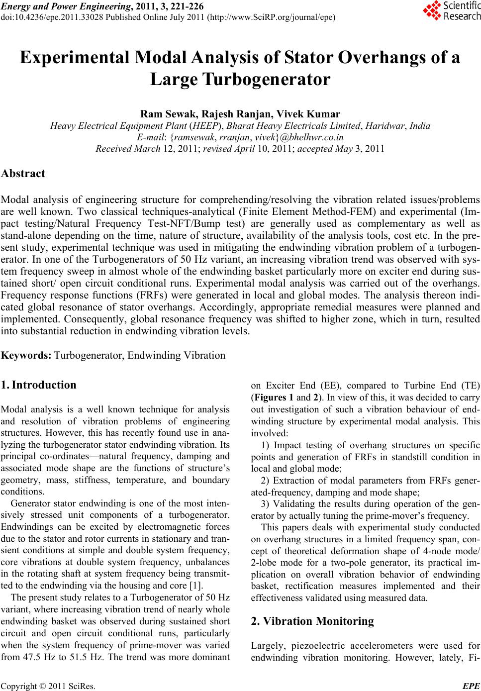 Energy and Power En gi neering, 2011, 3, 221-226 doi:10.4236/epe.2011.33028 Published Online July 2011 (http://www.SciRP.org/journal/epe) Copyright © 2011 SciRes. EPE Experimental Modal Analysis of Stator Overhangs of a Large Turbogenerator Ram Sewak, Rajesh Ranjan, Vivek Kumar Heavy Electrical Equipment Plant (HEEP), Bharat Heavy Electricals Limited, Haridwar, India E-mail: {ramsewak, rranjan, vivek}@bhelhwr.co.in Received March 12, 201 1; revised April 10, 2011; accepted May 3, 2011 Abstract Modal analysis of engineering structure for comprehending/resolving the vibration related issues/problems are well known. Two classical techniques-analytical (Finite Element Method-FEM) and experimental (Im- pact testing/Natural Frequency Test-NFT/Bump test) are generally used as complementary as well as stand-alone depending on the time, nature of structure, availability of the analysis tools, cost etc. In the pre- sent study, experimental technique was used in mitigating the endwinding vibration problem of a turbogen- erator. In one of the Turbogenerators of 50 Hz variant, an increasing vibration trend was observed with sys- tem frequency sweep in almost whole of the endwinding basket particularly more on exciter end during sus- tained short/ open circuit conditional runs. Experimental modal analysis was carried out of the overhangs. Frequency response functions (FRFs) were generated in local and global modes. The analysis thereon indi- cated global resonance of stator overhangs. Accordingly, appropriate remedial measures were planned and implemented. Consequently, global resonance frequency was shifted to higher zone, which in turn, resulted into substantial reduction in endwinding vibration levels. Keywords: Turbogenerator, Endwinding Vibration 1. Introduction Modal analysis is a well known technique for analysis and resolution of vibration problems of engineering structures. However, this has recently found use in ana- lyzing the turbogenerator stator endwinding vibration. Its principal co-ordinates—natural frequency, damping and associated mode shape are the functions of structure’s geometry, mass, stiffness, temperature, and boundary conditions. Generator stator endwinding is one of the most inten- sively stressed unit components of a turbogenerator. Endwindings can be excited by electromagnetic forces due to the stator and rotor currents in stationary and tran- sient conditions at simple and double system frequency, core vibrations at double system frequency, unbalances in the rotating shaft at system frequency being transmit- ted to the endwinding via the housing and core [1]. The present study relates to a Turbogenerator of 50 Hz variant, where increasing vibration trend of nearly whole endwinding basket was observed during sustained short circuit and open circuit conditional runs, particularly when the system frequency of prime-mover was varied from 47.5 Hz to 51.5 Hz. The trend was more dominant on Exciter End (EE), compared to Turbine End (TE) (Figures 1 and 2). In view of this, it was decided to carry out investigation of such a vibration behaviour of end- winding structure by experimental modal analysis. This involved: 1) Impact testing of overhang structures on specific points and generation of FRFs in standstill condition in local and global mode; 2) Extraction of modal parameters from FRFs gener- ated-frequency, damping and mode shape; 3) Validating the results during operation of the gen- erator by actually tuning the prime-mover’s frequency. This papers deals with experimental study conducted on overhang structures in a limited frequency span, con- cept of theoretical deformation shape of 4-node mode/ 2-lobe mode for a two-pole generator, its practical im- plication on overall vibration behavior of endwinding basket, rectification measures implemented and their effectiveness validated using measured data. 2. Vibration Monitoring Largely, piezoelectric accelerometers were used for endwinding vibration monitoring. However, lately, Fi- 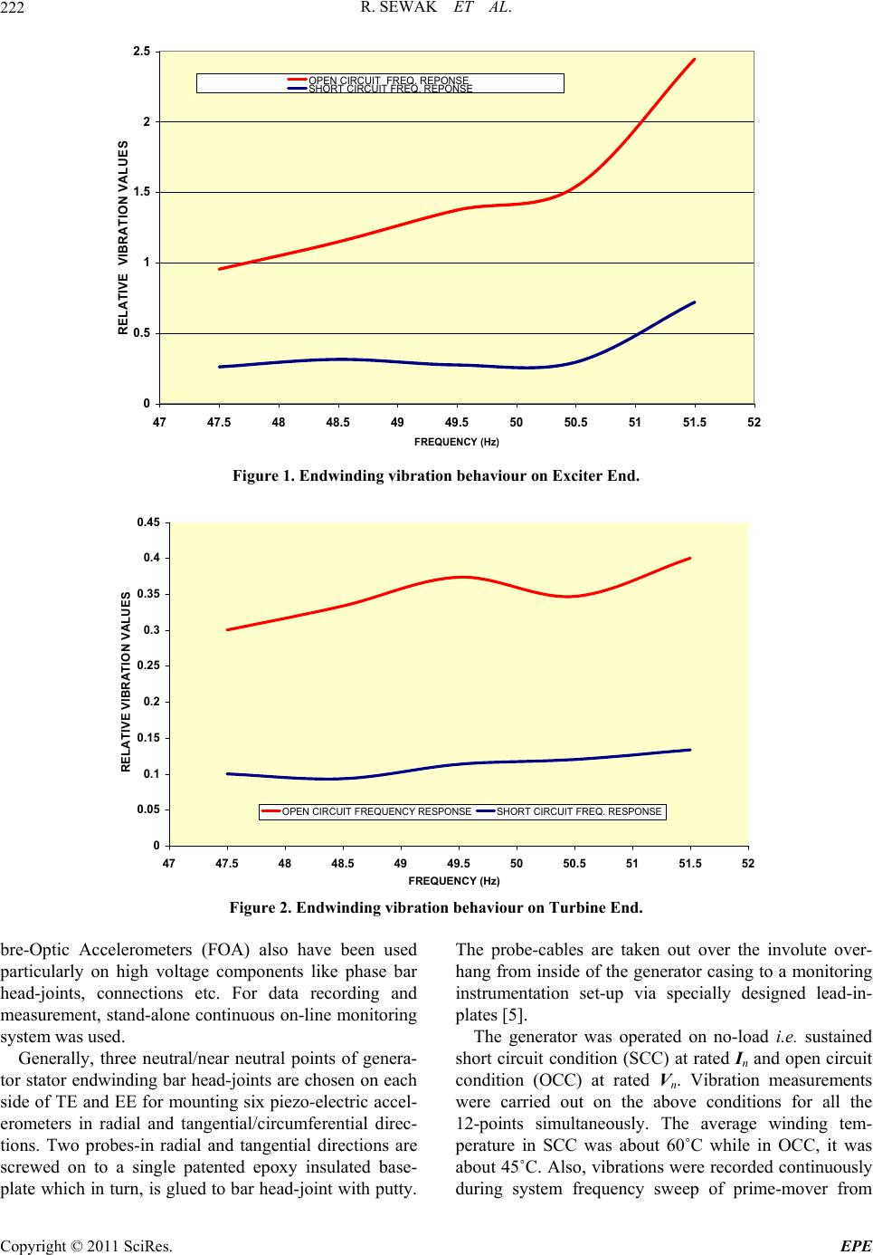 R. SEWAK ET AL. 222 0 0.5 1 1.5 2 2.5 47 47.5 48 48.5 49 49.5 50 50.5 51 51.5 52 FREQUENCY (Hz) RELATIVE VIBRATION VALUES OPEN CIRCUIT FREQ. REPONSE SHORT CIRCUITFREQ. REPONSE Figure 1. Endwinding vibration behaviour on Exciter End. 0 0.05 0.1 0.15 0.2 0.25 0.3 0.35 0.4 0.45 47 47.5 48 48.5 49 49.5 50 50.5 51 51.5 52 RELATIVE VIBRATION VALUES OPEN CIRCUIT F REQUENCY RESPONSESHORT CIRCUIT FREQ. RESPONSE FREQUENCY (Hz) Figure 2. Endwinding vibration behaviour on Turbine End. bre-Optic Accelerometers (FOA) also have been used particularly on high voltage components like phase bar head-joints, connections etc. For data recording and measurement, stand-alone continuous on-line monitoring system was used. Generally, three neutral/near neutral points of genera- tor stator endwinding bar head-joints are chosen on each side of TE and EE for mounting six piezo-electric accel- erometers in radial and tangential/circumferential direc- tions. Two probes-in radial and tangential directions are screwed on to a single patented epoxy insulated base- plate which in turn, is glued to bar head-joint with putty. The probe-cables are taken out over the involute over- hang from inside of the generator casing to a monitoring instrumentation set-up via specially designed lead-in- plates [5]. The generator was operated on no-load i.e. sustained short circuit condition (SCC) at rated In and open circuit condition (OCC) at rated Vn. Vibration measurements were carried out on the above conditions for all the 12-points simultaneously. The average winding tem- perature in SCC was about 60˚C while in OCC, it was about 45˚C. Also, vibrations were recorded continuously during system frequency sweep of prime-mover from Copyright © 2011 SciRes. EPE 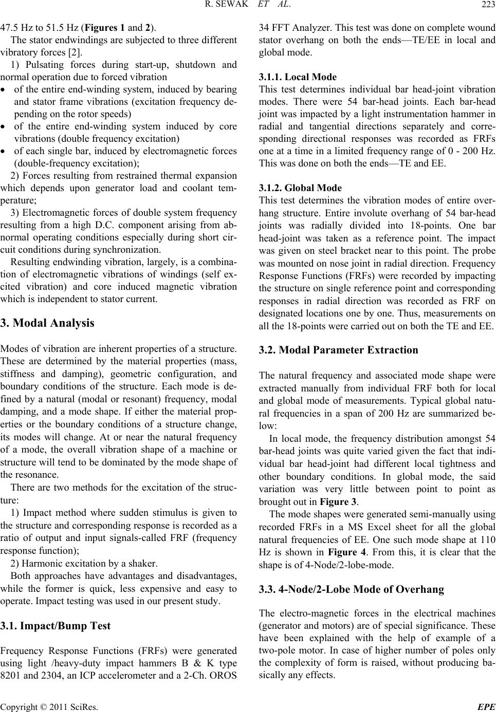 R. SEWAK ET AL.223 47.5 Hz to 51.5 Hz (Figures 1 and 2). The stator endwindings are subjected to three different vibratory forces [2]. 1) Pulsating forces during start-up, shutdown and normal operation due to forced vibration of the entire end-winding system, induced by bearing and stator frame vibrations (excitation frequency de- pending on th e rotor speeds) of the entire end-winding system induced by core vibrations (double frequency excitation) of each single bar, induced by electromagnetic forces (double-frequency ex citation); 2) Forces resulting from restrained thermal expansion which depends upon generator load and coolant tem- perature; 3) Electromagnetic forces of double system frequency resulting from a high D.C. component arising from ab- normal operating conditions especially during short cir- cuit conditions during synchronization. Resulting endwinding vibration, largely, is a combina- tion of electromagnetic vibrations of windings (self ex- cited vibration) and core induced magnetic vibration which is independent to stator current. 3. Modal Analysis Modes of vibration are inherent properties of a structure. These are determined by the material properties (mass, stiffness and damping), geometric configuration, and boundary conditions of the structure. Each mode is de- fined by a natural (modal or resonant) frequency, modal damping, and a mode shape. If either the material prop- erties or the boundary conditions of a structure change, its modes will change. At or near the natural frequency of a mode, the overall vibration shape of a machine or structure will tend to be dominated by the mode shape of the resonance. There are two methods for the excitation of the struc- ture: 1) Impact method where sudden stimulus is given to the structure and corresponding response is recorded as a ratio of output and input signals-called FRF (frequency response function); 2) Harmonic excitation by a shaker. Both approaches have advantages and disadvantages, while the former is quick, less expensive and easy to operate. Im pact test i ng was us ed in our present study. 3.1. Impact/Bump Test Frequency Response Functions (FRFs) were generated using light /heavy-duty impact hammers B & K type 8201 and 2304, an ICP accelerometer and a 2-Ch. OROS 34 FFT Analyzer. This test was done on complete wound stator overhang on both the ends—TE/EE in local and global mode. 3.1.1. Local Mode This test determines individual bar head-joint vibration modes. There were 54 bar-head joints. Each bar-head joint was impacted by a light instrumentation hammer in radial and tangential directions separately and corre- sponding directional responses was recorded as FRFs one at a time in a limited frequency range of 0 - 200 Hz. This was done on both the ends—TE and EE. 3.1.2. Glob al Mode This test determines the vibration modes of entire over- hang structure. Entire involute overhang of 54 bar-head joints was radially divided into 18-points. One bar head-joint was taken as a reference point. The impact was given on steel bracket near to this point. The probe was mounted on nose joint in radial direction. Frequency Response Functions (FRFs) were recorded by impacting the structure on single ref erence point and corresponding responses in radial direction was recorded as FRF on designated locations one by one. Thus, measurements on all the 18-points were carried out on both the TE and EE. 3.2. Modal Parameter Extraction The natural frequency and associated mode shape were extracted manually from individual FRF both for local and global mode of measurements. Typical global natu- ral frequencies in a span of 200 Hz are summarized be- low: In local mode, the frequency distribution amongst 54 bar-head joints was quite varied given the fact that indi- vidual bar head-joint had different local tightness and other boundary conditions. In global mode, the said variation was very little between point to point as brought out in Figure 3. The mode shapes were generated semi-manually using recorded FRFs in a MS Excel sheet for all the global natural frequencies of EE. One such mode shape at 110 Hz is shown in Figure 4. From this, it is clear that the shape is of 4-Node/2-lobe-mode. 3.3. 4-Node/2-Lobe Mode of Overhang The electro-magnetic forces in the electrical machines (generator and motors) are of special significance. These have been explained with the help of example of a two-pole motor. In case of higher number of poles only the complexity of form is raised, without producing ba- sically any effects. Copyright © 2011 SciRes. EPE 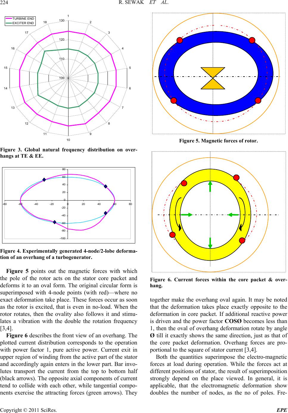 R. SEWAK ET AL. 224 100 110 120 130 1 2 3 4 5 6 7 8 9 10 11 12 13 14 15 16 17 18 TURBINE END EXCITER END Figure 3. Global natural frequency distribution on over- hangs at TE & EE. -100 -80 -60 -40 -20 0 20 40 60 80 -80 -60 -40 -20020406080 Figure 4. Expe rimentally generated 4-node/2-lobe deforma- tion of an overhang of a turbogenerator. Figure 5 points out the magnetic forces with which the pole of the rotor acts on the stator core packet and deforms it to an oval form. The original circular form is superimposed with 4-node points (with red)—where no exact deformation take place. These forces occur as soon as the rotor is excited, that is even in no-load. When the rotor rotates, then the ovality also follows it and stimu- lates a vibration with the double the rotation frequency [3,4]. Figure 6 describes the front view of an overhang. The plotted current distribution corresponds to the operation with power factor 1, pure active power. Current exit in upper region of winding from the active part of the stator and accordingly again enters in the lower part. Bar invo- lutes transport the current from the top to bottom half (black arrows). The opposite axial components of current tend to collide with each other, while tangential compo- nents exercise the attracting forces (green arrows). They Figure 5. Magnetic forces of rotor. Figure 6. Current forces within the core packet & over- hang. together make the overhang oval again. It may be noted that the deformation takes place exactly opposite to the deformation in core packet. If additional reactive power is driven and the power factor COSØ becomes less than 1, then the oval of overhang deformation rotate by angle Ø till it exactly shows the same direction, just as that of the core packet deformation. Overhang forces are pro- portional to the square of stator current [3,4]. Both the quantities superimpose the electro-magnetic forces at load during operation. While the forces act at different positions of stator, the result of superimposition strongly depend on the place viewed. In general, it is applicable, that the electromagnetic deformation show doubles the number of nodes, as the no of poles. Fre- Copyright © 2011 SciRes. EPE  R. SEWAK ET AL.225 quency is just the double grid frequency for all number of poles. Experimental mode shape generated from global frequency measurements are shown in Figure 4. 4. Analysis 1) Since the generator overhang including core vibrate at double the rotor frequency, the natural frequencies near to the system frequency of 50 or 60 Hz and twice the value, 100 or 120 Hz, are of special interest [1]. The generator was put on operation in SSC and OCC successively for about 4 to 5 hour in each regime, the average winding temperature recorded to about 60˚C and 45˚C respectively. Further, in stabilized conditions, when the drive motor frequency swept slowly from 47.5 Hz to 51.5 Hz, the vibration level on EE shot up sharply (Fig- ures 1 and 2), particularly from 50 Hz onwards. This behavior can be explained on the basis of structural dy- namics. In standstill condition i.e. at normal temperature condition, global natural frequency was obtained as 110 Hz (Table 1). As the generator run, the temperature of the overhang raised which brought down the natural fre- quency in the region of nearly 102 to 103 Hz. Since overhang excites at double the fundamental rotor fre- quency (2 × 50 Hz = 100 Hz) in a 2-pole machine, thus resonance phenomenon might have been occurred when the prime-mover’s frequency was swept from 50 Hz to 51.5 Hz. The reduction of natural frequency at elevated temperature from normal temperature has been reported by others as well [6]. However, the machine could not be operated beyond 51.5 Hz due to system’s limitations, otherwise exact value of resonance frequency would have been detected. On TE, generally, this phenomenon was not observed probably due to higher global natural frequency (Table 1). In addition to above, 4-node/2-lobe mode shape (Fig- ure 4) of generator ov erhang obtained at 110 Hz by mo- dal analysis might have been coincided with the theo- retical mode shape. This further aggravat ed the vibration behavior of ov e rhang. 2) Role of core vibration was also studied by carrying out impact test on it. Dominant natural frequency was found around 84 Hz which seemed to be quite safe from the resonance point of view. So, from the above description, it appeared that the Table 1. Typical global natural frequencies (Hz) obtained on overhangs. Global Mode (Hz) Local Mode (Hz) Turbine End Exciter End Turbine End. Exciter End 119.6, 146.6, 156.6 110, 122, 133117, 133, 146 110, 125, 148 global natural frequency and its associated 4-node mode of vibration seemed to be the principal cause for higher endwinding vibration on EE. 5. Rectifying Measures In order to arrest the vibration tend, suitable measures were planned and implemented. These measures pro- vided additional stiffness and overall strength to over- hang structure. Some of them are given below: 1) Continuous resin rope was introduced encircling all the bar-head joints in order to integrate the overall over- hang basket (Figure 7); 2) Additional bracing was provided, so as to increase the stiffness of overhang within phase and also at phase separation; 3) Concerned process bottlenecks were removed by suitable technological means. 6. Evaluation of Measures Subsequent to rectification and testing, following results were obtained: Overall global natural frequency was found to be in- creased about 5 Hz on EE and 10 Hz on TE from the un- rectified situation; Endwinding vibration level was reduced to nearly 1/3 to its previous level (Figure 8); No resonance like phenomenon was observed in any testing /operational regime. 7. Conclusions 1) Experimental modal analysis of overhang structures and subsequent operational runs of generator indicated global resonance phenomenon as the most likely cause for sharp increase endwinding vibration levels. Further, 4-node/2-lobe mode shape obtained by modal analysis seemed to have aggravated vibration behavior, thus, de- Figure 7. Rectification measure: a continuous resin rope integrating bar-head joints. Copyright © 2011 SciRes. EPE 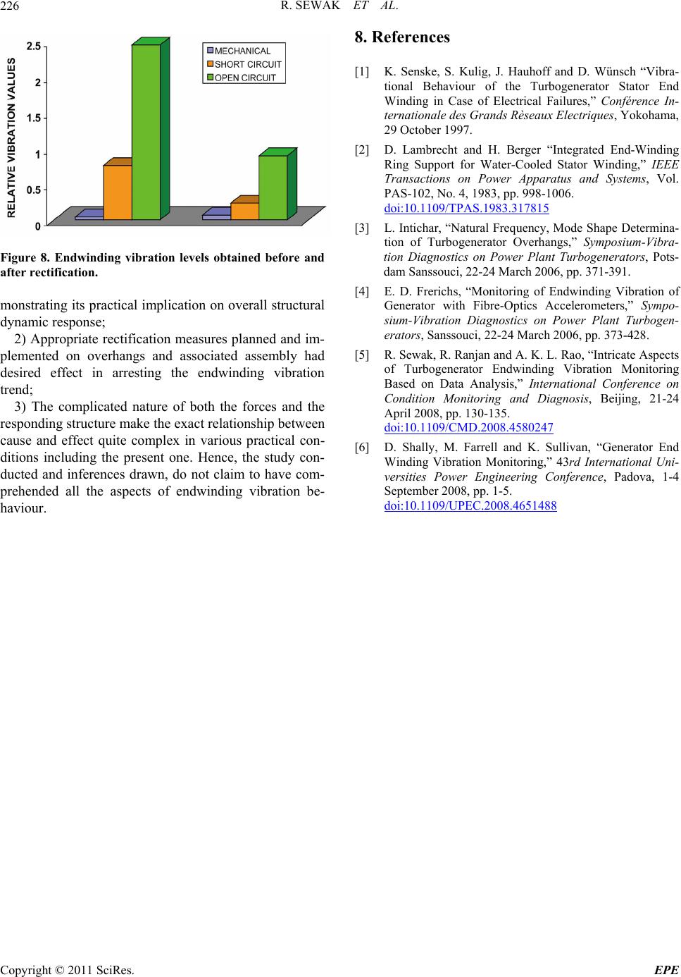 R. SEWAK ET AL. Copyright © 2011 SciRes. EPE 226 8. References [1] K. Senske, S. Kulig, J. Hauhoff and D. Wünsch “Vibra- tional Behaviour of the Turbogenerator Stator End Winding in Case of Electrical Failures,” Conférence In- ternationale des Grands Rèseaux Electriques, Yokohama, 29 October 1997. [2] D. Lambrecht and H. Berger “Integrated End-Winding Ring Support for Water-Cooled Stator Winding,” IEEE Transactions on Power Apparatus and Systems, Vol. PAS-102, No. 4, 1983, pp. 998-1006. doi:10.1109/TPAS.1983.317815 [3] L. Intichar, “Natural Frequency, Mode Shape Determina- tion of Turbogenerator Overhangs,” Symposium-Vibra- tion Diagnostics on Power Plant Turbogenerators, Pots- dam Sanssouci, 22-24 March 2006, pp. 371-391. Figure 8. Endwinding vibration levels obtained before and after rectificatio n. [4] E. D. Frerichs, “Monitoring of Endwinding Vibration of Generator with Fibre-Optics Accelerometers,” Sympo- sium-Vibration Diagnostics on Power Plant Turbogen- erators, Sanssouci, 22-24 March 2006, pp. 373-428. monstrating its practical implication on overall structural dynamic response; 2) Appropriate rectification measures planned and im- plemented on overhangs and associated assembly had desired effect in arresting the endwinding vibration trend; [5] R. Sewak, R. Ranjan and A. K. L. Rao, “Intricate Aspects of Turbogenerator Endwinding Vibration Monitoring Based on Data Analysis,” International Conference on Condition Monitoring and Diagnosis, Beijing, 21-24 April 2008, pp. 130-135. doi:10.1109/CMD.2008.4580247 3) The complicated nature of both the forces and the responding structure make the exact relationship between cause and effect quite complex in various practical con- ditions including the present one. Hence, the study con- ducted and inferences drawn, do not claim to have com- prehended all the aspects of endwinding vibration be- haviour. [6] D. Shally, M. Farrell and K. Sullivan, “Generator End Winding Vibration Monitoring,” 43rd International Uni- versities Power Engineering Conference, Padova, 1-4 September 2008, pp. 1-5. doi:10.1109/UPEC.2008.4651488 |