Journal of Applied Mathematics and Physics
Vol.04 No.01(2016), Article ID:62630,5 pages
10.4236/jamp.2016.41005
Development of Combined Trochoidal Profile of a Gerotor Pump
Hao Liu*, Jae-Cheon Lee
Department of Mechanical and Automotive Engineering, Keimyung University, Daegu, South Korea


Received 30 November 2015; accepted 5 January 2016; published 12 January 2016
ABSTRACT
Gerotor pumps are a kind of internal gear pump, widely used in applications of lubricating system of on-road or off-road engines. Normally their outer rotors are the circular arc profile while their inner rotor profile is the conjugate curve of the outer rotor. This research focuses on how to derive the combined trochoidal profile of a gerotor pump. The hypocycloidal and epicycloidal profile of the inner rotor is generated at first. And then the profile of the outer rotor, based on the inner rotor profile, is obtained by analytical approach and computationally graphical approach. The paper provides feasibility to develop the unconventional profile of a gerotor pump.
Keywords:
Hypocycloidal and Epicycloidal Profile, Conjugate Profile, Computationally Graphical Approach, Gerotor Pump

1. Introduction
It is well known that internal gear pumps have lower noise than external gear pumps because gears of the former rotate along the same direction, yielding lower relative velocity, while that of the latter do along the inverse direction with higher relative velocity. Moreover, the overlap coefficient of internal gear pumps is greater than that of external gear pumps, therefore the former rotates much more smoothly than the latter. Gerotor pumps belong to a kind of internal gear pumps, which are positive displacement pumps. Compared with external or other internal gear pumps, they have advantages of less components, simple structure, compact size, low noise, and low pulsation of flow rate. Therefore they are widely used in applications of lubricating system or fuel supply system of on-road or off-road engines [1]. The main components of a gerotor pump include an inner rotor, an outer rotor, and a housing in which inlet (suction) and outlet (delivery) ports are machined. The inner rotor is placed inside the outer rotor and it positions itself at a fixed eccentricity from the outer rotor center. The inner rotor is driven by input torque, generally generated by a motor or engine, and the outer rotor rotates with it since they contact each other at less several points of their geometrical profiles. Thus the profiles of the inner and outer rotors are a pair of conjugate curves.
The inner rotor has one tooth less than the outer rotor, and they have a special type of conjugate profiles which always ensure contact of the inner and outer rotors at several points [2]. The profile type of conventional gerotor pumps is trochoidal profile, which refers to any of the cycloid including the curtate cycloid and the prolate cycloid. This profile is widely used in profile generation of gerotor pumps [3]-[5]. Reference [6] utilized internal rolling method to design the profile of the inner rotor, which is the equidistant curve of the trochoid along the inside direction of the common normal line, and the circular arc profile of the outer rotor, as shown in Figure 1. This is a conventional profile type of gerotor pumps, about which researchers have done lots of work [7]-[9].
This paper proposes a combined trochoidal profile, i.e. hypocycloidal and epicycloidal curve, of the inner rotor, and the outer rotor is a conjugate profile of it. The generation of the combined trochoidal profile of the inner rotor is given in Section 2. And then the outer rotor profile, based on the inner rotor profile, is developed via analytical approach and computationally graphical approach stated in Section 3. The last section is conclusion.
2. Generation of Combined Trochoidal Profile of the Inner Rotor
The profile of the inner rotor is composed of a segment of hypocycloidal curve and a segment of epicycloidal curve. In order to connect the hypocycloid and epicycloid in radial direction, their base circles have the same radius of R1. And the following condition should be satisfied so that the hypocycloid and epicycloid could connect on the circumference of the base circle: the sum of circumferences of the rolling circles to generate hypocycloid and epicycloid is one Z1-th of the base circle circumference, namely the following equation.
 (1)
(1)
Of course, the hypocycloidal and epicycloidal curves can connect at a point on the circumference of the base circle but the slopes of their tangential lines at this point may be not same. It can be solved by adding a fillet between them
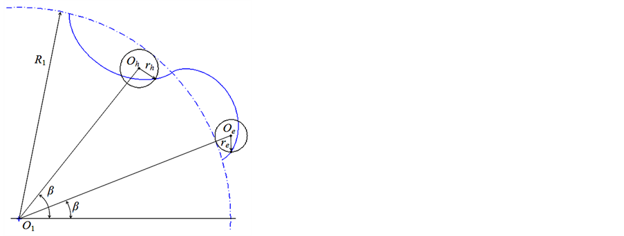
It is not difficult to derive the parametric equations of the hypocycloid and epicycloid, expressed by Equation (2) and (3), where β is parameter, the angle between the x-axis and the line determined by the center of the base circle, O1, and the center of the rolling circle of the hypocycloid or epicycloid, Oh or Oe, as shown in Figure 2(a). For the inner rotor with lobe number Z1 = 6, the whole profile is to repeat the segment of hypocycloidal or epicycloidal curve by six times along the circumference, as shown in Figure 2(b).
 (2)
(2)
 (3)
(3)

Figure 1. The trochoidal profile of the inner rotor and the circular arc profile of the outer rotor [3].
 (a) (b)
Figure 2. (a) A lobe of combined hypocycloidal and epicycloidal profile (b) Profile of the inner rotor and base circles of the inner and outer rotors.
The meshing principle of two rotors can be stated as following. When the inner rotor and the outer rotor rotate together around their centers O1 and O2, respectively, their pitch circles with radius of R1 and R2 actually rotate by contacting at the point P without slipping, as shown in Figure 2(b). The base circle of the inner rotor is served as the pitch circle here. The lobe number of the inner rotor is Z1 = 6 and the distance between the centers of two rotors is eccentricity, e. The following relations are adopted in the research: R1 = Z1e and R2 = Z2e [6]. As the inner and outer rotors rotating, their profiles form a pair of conjugate profiles. Now the problem is how to derive the outer rotor profile based on the hypocycloidal and epicycloidal profile of the inner rotor.
3. Development of Conjugate Profile
Base the combined trochoidal profile of the inner rotor, two different methods are proposed in this section. One is to obtain profile coordinates of the outer rotor according to the above meshing principle. The other is via graphical approach to determine the envelope curve of the outer rotor.
3.1. Analytical Representation
Now the geometrical relation of the inner and outer rotors is analyzed to derive the profile of the outer rotor, i.e. the conjugate profile of the inner rotor lobe. The pitch circle of the outer rotor is fixed and let that of the inner rotor rotate along the former. The center of the inner rotor, O1, moves to O’1 as the contact point P moves to P’, as shown in Figure 3. The angle between line O2O1 and line O2O’1 is θ. Considering that the rotated arcs of the pitch circles of the inner and outer rotors are of the same length, the rotary angle of the inner rotor is
 (4)
(4)
In fact, the contact point of the inner and outer rotors at this rotary angle is point N, which has corresponding coordinates for the inner and outer rotors, Nin(xin, yin) and Nout(xout, yout), respectively. Considering the polar angle of the point Nin(xin, yin) on the inner rotor, the following Equation (5) establishes.
 (5)
(5)
By using the rotary matrix, coordinates of the conjugate point Nout(xout, yout) are expressed by Equation (6), which gives the analytical equation for the profile of the outer rotor.
 (6)
(6)
3.2. Computationally Graphical Approach
Graphical approach to obtain the conjugate profile of the outer rotor is simple, intuitive, and practical, but with shortcoming of low precision. However, precision of graphical approach can be greatly improved with the aid of a computer. By this approach, the outer rotor is fixed at first, and let the pitch circle of the inner rotor rotate along the inside of the pitch circle of the outer rotor without slipping. With rotation of the inner rotor, its lobe profile will form family of curves, and the outer envelope curve is right the profile of the outer rotor, as illustrated in Figure 4. It is not difficult, with numerical computation, to find coordinates of the lobe profile as the inner rotor locates in different rotary angles and coordinates of the outer envelope curve, namely the profile of the outer rotor.
4. Conclusion
Trochoidal profile is widely applied on gerotor pumps. However, the combined profile of a gerotor pump is investigated in the paper. The hypocycloidal and epicycloidal profile of the inner rotor is generated firstly. And then the profile of the outer rotor, the conjugate profile of the inner rotor, is developed. In order to find the con-jugate profile of the combined trochoid, two approaches are proposed. The analytical equation of the conjugate curve is obtained by analysis of geometrical relation. On the other hand computationally graphical approach is feasible via the numerical computation. The next work is to optimize the designed conjugate profiles and im prove performances of the gerotor pump, such as flow rate pulsation, volumetric efficiency, and so on.

Figure 3. Rotation of the pitch circle of the inner rotor along that of the outer rotor without slipping.

Figure 4. Profile of the outer rotor: outer envelope curve of the inner rotor lobe.
Acknowledgements
This research was supported by the Ministry of Trade, Industry & Energy (MOTIE) and Korea Evaluation Institute of Industrial Technology (KEIT) through the Project of Industrial Core Technology Development, in which the research titled “Development of hydraulically shifted auto navigation tractor with self-diagnosis based on integrated load control”(Project No. 10049226).
The authors are also grateful to the support of the Center for Automotive Mechatronics Parts (CAMP) at Keimyung University granted by the MOTIE and Korea Institute for Advancement of Technology (KIAT).
Cite this paper
Hao Liu,Jae-Cheon Lee, (2016) Development of Combined Trochoidal Profile of a Gerotor Pump. Journal of Applied Mathematics and Physics,04,28-32. doi: 10.4236/jamp.2016.41005
References
- 1. Lingeswaramurthy, P., Jayabhaskar, J., Elayaraja, R. and Suresh Kumar, J. (2011) Development of Analytical Modelfor Design of Gerotor Oil Pump and Experimental Validation. SAE International Journal of Engines, 4, 441-449. http://dx.doi.org/10.4271/2011-01-0402
- 2. Jamadar, M., Jose, A., Ramdasi, S. and Marathe, N. (2013) Development of In-House Competency to Build CompactGerotor Oil Pump for High Speed Diesel Engine Application. SAE Technical Paper. http://dx.doi.org/10.4271/2013-01-2738
- 3. Mancò, S., Nervegna, N., Rundo, M., Armenio, G., Pachetti, C. and Trichilo, R. (1998) Gerotor Lubricating Oil Pumpfor IC Engines. SAE Technical Paper, 982689.
- 4. Fabiani, M., Mancò, S., Nervegna, N., Rundo, M., Armenio, G., Pachetti, C. and Trichilo, R. (1999) Modelling and Simulation of Gerotor Gearing in Lubricating Oil Pumps. SAE Technical Paper.
- 5. Mancò, S., Nervegna, N. and Rundo, M. (2000) Effects of Timing and Odd/Even Number of Teeth on Noise Generation of Gerotor Lubricating Pumps for IC Engines. SAE Technical Paper. http://dx.doi.org/10.4271/2000-01-2630
- 6. Liu, H., Lee, J.-C., Yoon, A. and Kim, S.-T. (2015) Profile Design and Numerical Calculation of Instantaneous Flow Rate of a Gerotor Pump. Journal of Applied Mathematics and Physics, 3, 92-97. http://dx.doi.org/10.4236/jamp.2015.31013
- 7. Zhang, D., Perng, C. and Laverty, M. (2006) Gerotor Oil Pump Performance and Flow/Pressure Ripple Study. SAETechnical Paper. http://dx.doi.org/10.4271/2006-01-0359
- 8. Elayaraja, R., Lingeswaramurthy, P. and Govindarajan, S. (2009) Performance of Gerotor Oil Pump for an Automotive Engine-Prediction Using CFD Analysis and Experimental Validation. SAE Technical Paper.
- 9. Srinivasan, S., Kumar, J.S., Vijayakumar, K. and Venkataraman, P. (2012) Performance Improvement of AutomotiveOil Pump to Operate at High Temperatures Employed in Modern Diesel Engines. SAE Technical Paper.
Nomenclature

NOTES

*Corresponding author.