Paper Menu >>
Journal Menu >>
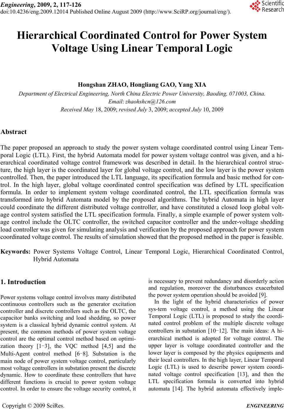 Engineering, 2009, 2, 117-126 doi:10.4236/eng.2009.12014 Published Online August 2009 (http://www.SciRP.org/journal/eng/). Copyright © 2009 SciRes. ENGINEERING Hierarchical Coordinated Control for Power System Voltage Using Linear Temporal Logic Hongshan ZHAO, Hongliang GAO, Yang XIA Department of Electrical Engineering, North China Electric Power University, Baoding, 071003, China. Email: zhaohshcn@126.com Received May 18, 2009; revised July 3, 2009; accepted July 10, 2009 Abstract The paper proposed an approach to study the power system voltage coordinated control using Linear Tem- poral Logic (LTL). First, the hybrid Automata model for power system voltage control was given, and a hi- erarchical coordinated voltage control framework was described in detail. In the hierarchical control struc- ture, the high layer is the coordinated layer for global voltage control, and the low layer is the power system controlled. Then, the paper introduced the LTL language, its specification formula and basic method for con- trol. In the high layer, global voltage coordinated control specification was defined by LTL specification formula. In order to implement system voltage coordinated control, the LTL specification formula was transformed into hybrid Automata model by the proposed algorithms. The hybrid Automata in high layer could coordinate the different distributed voltage controller, and have constituted a closed loop global volt- age control system satisfied the LTL specification formula. Finally, a simple example of power system volt- age control include the OLTC controller, the switched capacitor controller and the under-voltage shedding load controller was given for simulating analysis and verification by the proposed approach for power system coordinated voltage control. The results of simulation showed that the proposed method in the paper is feasible. Keywords: Power Systems Voltage Control, Linear Temporal Logic, Hierarchical Coordinated Control, Hybrid Automata 1. Introduction Power systems voltage control involves many distributed continuous controllers such as the generator excitation controller and discrete controllers such as the OLTC, the capacitor banks switching and load shedding, so power system is a classical hybrid dynamic control system. At present, the common methods of power system voltage control are the optimal control method based on optimi- zation theory [1-3], the VQC method [4,5] and the Multi-Agent control method [6-8]. Substation is the main node of power system voltage control, particularly most voltage controllers in substation present the discrete dynamic. How to coordinate these controllers that have different functions is crucial to power system voltage control. In order to ensure the voltage security control, it is necessary to prevent redundancy and disorderly action and regulation, moreover the disturbances exacerbated the power system operation should be avoided [9]. In the light of the hybrid characteristics of power sys-tem voltage control, a method using the Linear Temporal Logic (LTL) is proposed to study the coordi- nated control problem of the multiple discrete voltage controllers in substation [10-12]. The main ideas: A hi- erarchical method is adopted for voltage control. The upper layer is voltage coordinated controller and the lower layer is composed by the physics equipments and their local controllers. In the high layer, Linear Temporal Logic (LTL) is used to describe power system coordi- nated voltage control specification [13], and then the LTL specification formula is converted into hybrid automata [14]. The hybrid automata effectively imple- 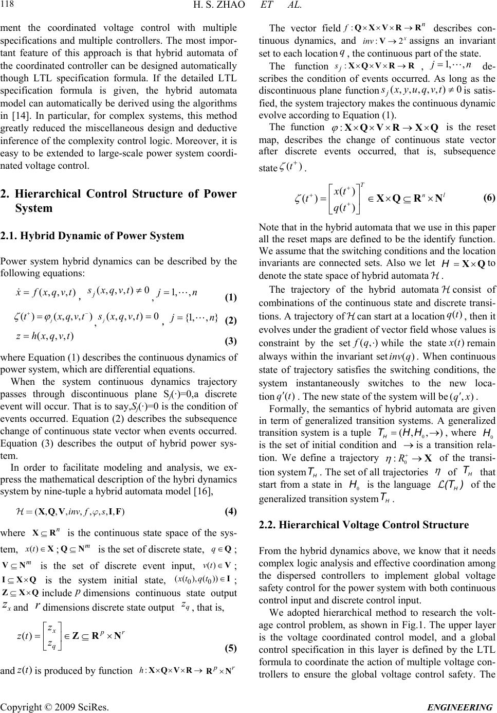 H. S. ZHAO ET AL. Copyright © 2009 SciRes. ENGINEERING 118 ment the coordinated voltage control with multiple specifications and multiple controllers. The most impor- tant feature of this approach is that hybrid automata of the coordinated controller can be designed automatically though LTL specification formula. If the detailed LTL specification formula is given, the hybrid automata model can automatically be derived using the algorithms in [14]. In particular, for complex systems, this method greatly reduced the miscellaneous design and deductive inference of the complexity control logic. Moreover, it is easy to be extended to large-scale power system coordi- nated voltage control. 2. Hierarchical Control Structure of Power System 2.1. Hybrid Dynamic of Power System Power system hybrid dynamics can be described by the following equations: (,,,) x fxqvt ,, (1) (, ,,)0 j sxqvt1, ,jn () (,,,) j txqv t (,,,) 0 j sxqvt ,, (2) {1,, }jn (,,,)zhxqvt (3) where Equation (1) describes the continuous dynamics of power system, which are differential equations. When the system continuous dynamics trajectory passes through discontinuous plane Sj(·)=0,a discrete event will occur. That is to say,Sj(·)=0 is the condition of events occurred. Equation (2) describes the subsequence change of continuous state vector when events occurred. Equation (3) describes the output of hybrid power sys- tem. In order to facilitate modeling and analysis, we ex- press the mathematical description of the hybri dynamics system by nine-tuple a hybrid automata model [16], (,,, ,,,,,)inv fsXQV IFj= (4 ) where is the continuous state space of the sys- tem, ; is the set of discrete state, n XR ()xt Xm QN q Q ()vt ; is the set of discrete event input, m NV V 00 ( ))t ; is the system initial state, IXQ (( )xt ,q I; include dimensions continuous state output ZXQ p x zand dimensions discrete state output , that is, rq z () xpr q z zt z ZR N (5) and is produced by function ()zt :hXQVR pr RN The vector field:n f QXVR R :2 X inv V q describes con- tinuous dynamics, and assigns an invariant set to each location, the continuous part of the state. The function : j s XQVRR (, , j , de- scribes the condition of events occurred. As long as the discontinuous plane function 1, ,jn ,,) 0, s xyuqvt is satis- fied, the system trajectory makes the continuous dynamic evolve according to Equation (1). The function :XQVRXQ is the reset map, describes the change of continuous state vector after discrete events occurred, that is, subsequence state ()t . () () () T n xt tqt l XQ RN (6) Note that in the hybrid automata that we use in this paper all the reset maps are defined to be the identify function. We assume that the switching conditions and the location invariants are connected sets. Also we let XQHto denote the state space of hybrid automata. The trajectory of the hybrid automataconsist of combinations of the continuous state and discrete transi- tions. A trajectory ofcan start at a location, then it evolves under the gradient of vector field whose values is constraint by the set qt () (, ) f q while the state() x tremain always within the invariant set. When continuous state of trajectory satisfies the switching conditions, the system instantaneously switches to the new - tion ()qt ()inv q loca . The new state of the systell bem wi(,qx) . Formally, the semantics of hybrid automata are given in term of generalized transition systems. A generalized transition system is a tuple 0, where (,, ) H THH 0 H is the set of initial condition and is a transition rela- tion. We define a trajectory 0 :R X of the transi- tion system. The set of all trajectories H T of that start from a state in is the language of the generalized transition system. H T ) 0 HH (T H T 2.2. Hierarchical Voltage Control Structure From the hybrid dynamics above, we know that it needs complex logic analysis and effective coordination among the dispersed controllers to implement global voltage safety control for the power system with both continuous control input and discrete control input. We adopted hierarchical method to research the volt- age control problem, as shown in Fig.1. The upper layer is the voltage coordinated control model, and a global control specification in this layer is defined by the LTL formula to coordinate the action of multiple voltage con- trollers to ensure the global voltage control safety. The 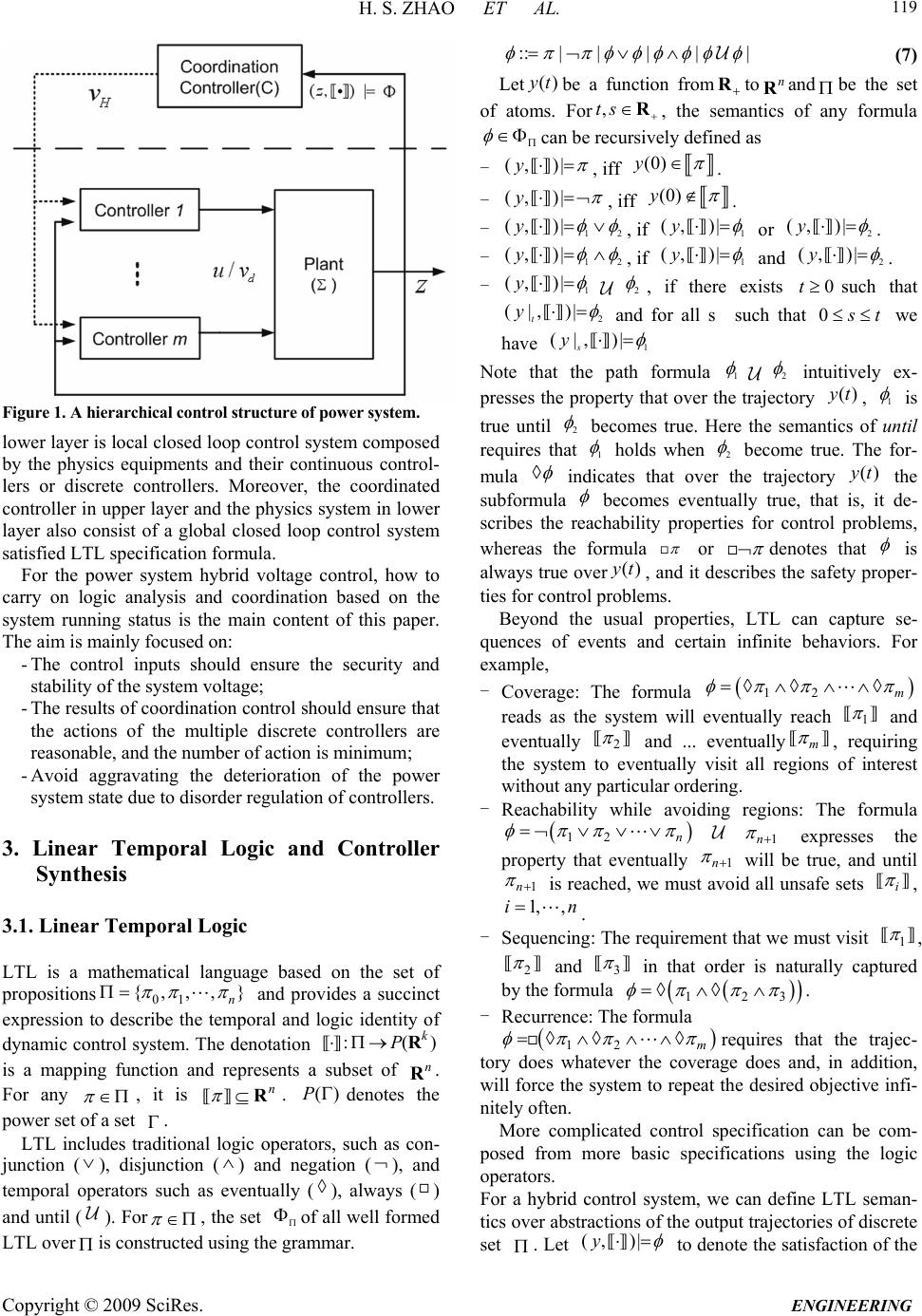 H. S. ZHAO ET AL. Copyright © 2009 SciRes. ENGINEERING 119 Figure 1. A hierarchical control structure of power system. lower layer is local closed loop control system composed by the physics equipments and their continuous control- lers or discrete controllers. Moreover, the coordinated controller in upper layer and the physics system in lower layer also consist of a global closed loop control system satisfied LTL specification formula. For the power system hybrid voltage control, how to carry on logic analysis and coordination based on the system running status is the main content of this paper. The aim is mainly focused on: - The control inputs should ensure the security and stability of the system voltage; - The results of coordination control should ensure that the actions of the multiple discrete controllers are reasonable, and the number of action is minimum; - Avoid aggravating the deterioration of the power system state due to disorder regulation of controllers. 3. Linear Temporal Logic and Controller Synthesis 3.1. Linear Temporal Logic LTL is a mathematical language based on the set of propositions 01 {,,, } n and provides a succinct expression to describe the temporal and logic identity of dynamic control system. The denotation is a mapping function and represents a subset of . For any :( k PR n R ) , it is n R. denotes the power set of a set . ()P LTL includes traditional logic operators, such as con- junction (), disjunction () and negation ( ), and temporal operators such as eventually (), always () and until ( ). For , the set of all well formed LTL overis constructed using the grammar. ::||||| (7) Let be a function fromtoand be the set of atoms. For ()yt Rn R ,ts R , the semantics of any formula can be recursively defined as - (, )|y , iff (0)y . - (, )|y , iff (0)y . - 12 (, )|y , if 1 (, )|y or 2 (, )|y . - 12 (, )|y , if 1 (, )|y and 2 (, )|y . - 1 (, )|y 2 , if there exists 0tsuch that 2 (|,)| t y and for all s such that 0 s t we have )| s1 (|,y Note that the path formula 1 2 intuitively ex- presses the property that over the trajectory , ()yt1 is true until 2 becomes true. Here the semantics of until requires that 1 holds when 2 become true. The for- mula indicates that over the trajectory the subformula ()yt becomes eventually true, that is, it de- scribes the reachability properties for control problems, whereas the formula or denotes that is always true over, and it describes the safety proper- ties for control problems. ()yt Beyond the usual properties, LTL can capture se- quences of events and certain infinite behaviors. For example, - Coverage: The formula 12 m reads as the system will eventually reach 1 and eventually 2 and ... eventuallym , requiring the system to eventually visit all regions of interest without any particular ordering. - Reachability while avoiding regions: The formula 12 n 1n expresses the property that eventually 1n will be true, and until 1n is reached, we must avoid all unsafe sets i , 1, ,in . - Sequencing: The requirement that we must visit 1 , 2 and 3 in that order is naturally captured by the formula 123 . - Recurrence: The formula 12 m requires that the trajec- tory does whatever the coverage does and, in addition, will force the system to repeat the desired objective infi- nitely often. More complicated control specification can be com- posed from more basic specifications using the logic operators. For a hybrid control system, we can define LTL seman- tics over abstractions of the output trajectories of discrete set . Let (,)|y to denote the satisfaction of the 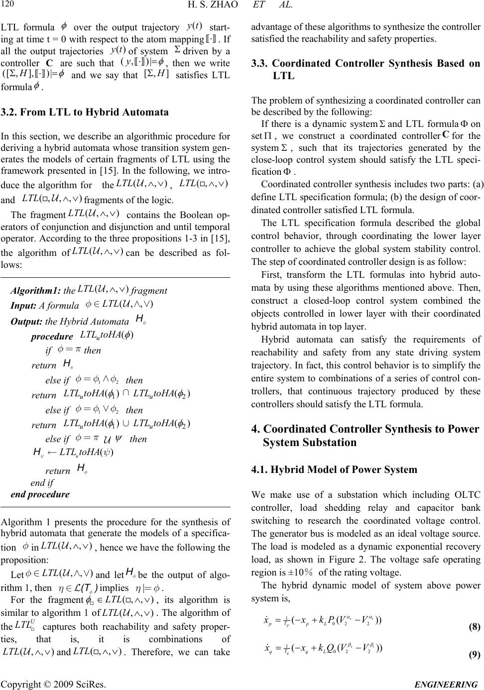 H. S. ZHAO ET AL. Copyright © 2009 SciRes. ENGINEERING 120 LTL formula over the output trajectory start- ing at time t = 0 with respect to the atom mapping ()yt . If all the output trajectories of system driven by a controller are such that ()yt (,y C)| , then we write ([ ,],H)| and we say that [, ] H satisfies LTL formula . 3.2. From LTL to Hybrid Automata In this section, we describe an algorithmic procedure for deriving a hybrid automata whose transition system gen- erates the models of certain fragments of LTL using the framework presented in [15]. In the following, we intro- duce the algorithm for the (,,)LTL , (,LTL ,) and (,, , )LTL fragments of the logic. The fragment(,LTL ,) contains the Boolean op- erators of conjunction and disjunction and until temporal operator. According to the three propositions 1-3 in [15], the algorithm of(,LTL ,) c (,, an be described as fol- lows: Algorithm1: the)LTL fragment Input: A formula (,LTL ,)Îf Output: the Hybrid Automata f H ) procedure (HA u LTLto if then f= H LT p return p else if then 12 f 1 () ff= return u L toHA Ç2 () u LTL toHA else if then 12 f 1 () ff = return u L toHALT È2 () u LTL toHA else if fp= then ¬H ()y u L toHALT (, y LTL return f H end if end procedure Algorithm 1 presents the procedure for the synthesis of hybrid automata that generate the models of a specifica- tion in f,) , hence we have the following the proposition: Let f(,,)LTLÎ and letbe the output of algo- rithm 1, then f H f hÎ(T)implies . |hf= , ) For the fragment(,LTL (,LTL ,) , its algorithm is similar to algorithm 1 of . The algorithm of the captures both reachability and safety proper- ties, that is, it is combinations of U LTL (,LTL ,) and . Therefore, we can take advantage of these algorithms to synthesize the controller satisfied the reachability and safety properties. (, L,) LT 3.3. Coordinated Controller Synthesis Based on LTL The problem of synthesizing a coordinated controller can be described by the following: If there is a dynamic systemand LTL formula on set , we construct a coordinated controllerfor the system C , such that its trajectories generated by the close-loop control system should satisfy the LTL speci- fication . Coordinated controller synthesis includes two parts: (a) define LTL specification formula; (b) the design of coor- dinated controller satisfied LTL formula. The LTL specification formula described the global control behavior, through coordinating the lower layer controller to achieve the global system stability control. The step of coordinated controller design is as follow: First, transform the LTL formulas into hybrid auto- mata by using these algorithms mentioned above. Then, construct a closed-loop control system combined the objects controlled in lower layer with their coordinated hybrid automata in top layer. Hybrid automata can satisfy the requirements of reachability and safety from any state driving system trajectory. In fact, this control behavior is to simplify the entire system to combinations of a series of control con- trollers, that continuous trajectory produced by these controllers should satisfy the LTL formula. 4. Coordinated Controller Synthesis to Power System Substation 4.1. Hybrid Model of Power System We make use of a substation which including OLTC controller, load shedding relay and capacitor bank switching to research the coordinated voltage control. The generator bus is modeled as an ideal voltage source. The load is modeled as a dynamic exponential recovery load, as shown in Figure 2. The voltage safe operating region is ±10% of the rating voltage. The hybrid dynamic model of system above power system is, 1 02 2 (( st p T ppL xxkPVV )) (8) 1 02 2 (( st q T qqL xxkQVV )) (9)  H. S. ZHAO ET AL. Copyright © 2009 SciRes. ENGINEERING 121 S Slack V=1,th... V0 V1 T V2 jx 1 + j 0. 2 j0.1 j0.1 Figure 2. A simple power system. 02 () 02 0(1 )()sin t T VV kiX Lp kx PV (10) 2 20 2 2 2 () 02 02 () 0(1 )()cos t TT VV V kiX Lq C kiX kxQV kBV (11) where are the active power recovery time con- stant and reactive power recovery time constant respec- tively, , pq TT , s t VV are the steady-state dependency, , s t VV are the transient dependency. [] T pq x xx T represents the load internal states, and[] y V ] is alge- braic variables. represents the dis- crete control input included the OLTC ratio, load shed- ding ratio and capacitor banks switching ratio. [T TLC vkkk Discrete control input depends on all discrete con- troller action. When does not change, Equation (8)-(11) will evolve continuously. In order to describe the discrete dynamic behavior of each voltage controllers, their hybrid automata models are given in next section. v v 4.2. The Automata Model of OLTC Controller The control behavior of OLTC can be described by the following mathematical model: ()(1)() TT kikidf V (12) where is the OLTC ratio of the ith regulation; is the OLTC regulation step, is the voltage deviation, is reference voltage; () T ki V d r VVV ( r) f V denotes up or down of OLTC regulation, its expression is 1max 2 1min 2 1()( () 1()()( 0others Brtd T Brtd T VD tTkn fVVDt Tkn () ) ) 4 (13) where, is the sum of OLTC timer delay and me- chanical delay, are the maximum and mini- mum regulation tap respectively. td T max min ,nn The OLTC control behavior described by model (12) can be described by a hybrid automata model, as shown Figure.3. The regulation condition of up or down of OLTC regulation is as follows 13up ttt (14) 0 q 1 q 2 q dn up rt rt Figure 3. Automata model of OLTC controller. 23dn ttt5 (15) 6rt t (16) where, atomic proposition 1 12 () t VD 0 B denotes the regulation condition when voltage is larger than the set value; 1 22 () t VD 0 B denotes the regula- tion condition when voltage is lower than the set value. 3() trtd tT 0 (() tT ki denotes OLTC delay of tap regula- tion; 4ma )0 T kx ,5min (() )0 tTT ki k , 6() trrt tT 0 . 4.3. The Automata Model of Capacitor Switch- ing Controller Switching capacitors can produce or reduce system reac- tive power. The term in Equation (11) is the reactive power produced by the capacitor banks switched. The switching conditions are as follows: when power factor is lower than the setting value and at the same time the voltage increase slowly, we switch on the capacitor; when power factor is larger than the set value and the bus voltage is higher than the setting value requested, the capacitor is switched off. 2 0c KBV The condition of switching capacitor is described as follows, 13 5 s wc cc (17) 24rmccc5 (18) 6rc c (19) The atomic propositions of the switching condition are 1mi cos 0 cf n , 2max (cos) 0 cf , 3c 0 csw VV , , 40 ccrm VV 50 crc tT 6 , 0 rc tT cr . The control behavior is similar to the OLTC controller, its automata model is as shown in Figure 4. 0 q 1 q 2 q rm s w rc rc Figure 4. The automata model of capacitor banks switching.  H. S. ZHAO ET AL. Copyright © 2009 SciRes. ENGINEERING 122 4.4. The Automata Model of Load Shedding Controller Load shedding is the final measure used to avoid a wide area voltage instability and voltage collapse when all other effective measures are exhausted. The condition of load shedding is: (i) The system active power safety margin is less the setting, that is s et ; (ii) The volt- age fall to 85~95% of normal for a minimum of 5 sec- onds. The automatic recovery of load isn’t considered in this paper. The conditions mentioned above can be writ- ten as follow, SS 123 s hs ss (20) 4rhs (21) The atomic propositions are1() sset SS 0 , 2(0.90) 0 sV , 3( sr )0 s tT 4( , ) s rr tT s . 0 The automata model of load shedding is shown in Figure 5. 4.5. The Coordinated Controller on Substation In order to avoid the voltage instability or collapse, the OLTC regulation, capacitor banks switching and load shedding in substation have to coordinate with their ac- tion each other, otherwise, would lead to control disorder and even aggravate the deterioration of the voltage. a) The coordinated control LTL specification formula The action principle of coordinated controller: if power system is lack of reactive power or in heavy load or power safety margin close to its settings, the capacitor should be switched on; if all capacitor banks are switched on, and the safety margin of power is still out- side its settings, some load should be shed. At the same time, in order to avoid system voltage instability or col- lapse, lock the OLTC controller. For the OLTC controller, its LTL formula of the coor- dinated adjustment is as follows 12 ( Tt ) t (22) For capacitor banks switching, the coordinated action LTL formula is 12 ( Cc ) c (23) 0 q 1 q s h rs Figure 5. Automata model of load shedding. For load shedding, the coordinated action LTL for- mula is 12 ( SsscT ()) (2 4) where, max () cCC kk 0 T denotes that all capacitor banks are switched on, denotes to lock the OLTC operation during the load shedding. The final LTL formula of coordinated controller is C 12 () t H tTCS (25) where 12tt denotes that the system is in the steady-state and has not any control action. b) Transform the LTL formula into the Hybrid Auto- mata In order to implement the LTL specification formula of coordinated controller, the formula H will be con- verted to hybrid automata by those algorithms introduced above. The hybrid automata model of LTL formula is shown in Figure 6. In Figure 6, 01tt2 , and the symbol 0 denotes that the system is in the steady-state and has not any control. 112tt , and 1 denotes that the coordinated controller allow the OLTC controller to regulate. 212cc , and 2 denotes allowing the capacitor banks switching. 312 s s , 3 denotes allowing load shedding. 4 denotes allowing the OLTC to be regulated after capacitor banks switching. 5 denotes allowing the OLTC to be regulated after load shedding. 5. Numerical Simulation In order to verify the validity of power system voltage hierarchical coordinated control based on LTL formula, the operating process of the coordinated controller and the dynamic behavior of power system under several disturbances are simulated on the platform of Dymola. ()C 0 1 2 3 5 4 Figure 6. The hybrid automata of the LTL formula H .  H. S. ZHAO ET AL. Copyright © 2009 SciRes. ENGINEERING 123 0100 200 300 400 50 0 0.76 0.8 0.84 0.88 0.92 0.96 1 1.04 Bus 2 .V (a) 0100 200 300 400 50 0 0.98 1 1.02 1.04 OLTC.y (b) 0100 200 300 40050 0 -0.2 -0.1 0 0.1 0.2 CAP.y (c) Figure 7. The voltage curve without coordination on bus 2 and the actions of discrete controllers. 5.1. Fault Occurred under Normal State A permanent short-circuit fault occurred under normal state at 20 seconds and it was cleared after 0.1 second. 1) Without any coordination The voltage simulating curve without any coordination on the low voltage side bus2 is shown as Figure 7(a) and the actions of the discrete controllers are shown as Figure 7(b) and Figure 7(c). We can know that one bank of ca- pacitor is switched on, at the same time, the OLTC con- troller has been up-regulated 3 times, then down-regu- lated 3 times. But in practice the operation of OLTC controller repeatedly is not desired since it reduces the lifetime of contact of executer. 2) The operating process with coordinated controller The voltage simulating curve and the actions of discrete controllers with coordination are shown as Fig.8. We can know that the results of action of controller under the coordination: the capacitors needn’t to be put, only the OLTC controller has been up-regulated 7 times, and the voltage finally stabilized at its allowed level. It can thus be seen that in such circumstances, only by regulating OLTC, can make the voltage to satisfy system requirements. This shows that the reactive power is ade- quate under normal conditions, so don’t need input ca- pacitors and only depending on LOTC regulation would be able to meet the requirements of voltage. As can be seen from Figure 7 without any coordination, the input capacitor led to the OLTC regulation up-regulated and down-regulated repeatedly. 5.2. Fault Occurred under Reactive Power Deficiency A permanent short-circuit fault occurred under reactive power deficiency state at 20 seconds and it was cleared after 0.1 second. Some cases involved in discrete con- trollers are discussed in the following. 1) Only the OLTC regulated For the system under the reactive power deficient in Figure 2, if only OLTC regulated, the voltage collapsed finally. Shown as Figure 9, the system voltage collapsed near 710 seconds. This is because the reactive power is deficiency, so the adjustment of OLTC not only can’t make voltage satisfy system requirements, but will made system further deteriorating. 2) The OLTC locked If locked OLTC, the system collapse could be avoid and the voltage eventually be stable at low value 0.78 p.u., shown as Figure 10. However, the level of voltage is far from the system requirements. 0100 200 300 400 50 0 0.76 0.8 0.84 0.88 0.92 0.96 1 Bus2. V (a) 0100 200300 400 50 0 0.98 1 1.02 1.04 1.06 1.08 1.1OLTC.y (b) Figure 8. The voltage curve with coordination on bus 2 and the actions of discrete controllers.  H. S. ZHAO ET AL. Copyright © 2009 SciRes. ENGINEERING 124 0100 200 300 400500 600 700 80 0 0.5 0.6 0.7 0.8 0.9 1 Bus2.V (a) 0100 200 300 400500 600 700 80 0 1 1.04 1.08 1.12 OLTC.y (b) Figure 9. The voltage curve on bus 2 and the actions of dis- crete controllers. 0100 200 300 400 500 600 700 80 0 0.65 0.7 0.75 0.8 0.85 0.9 0.95 1 1.05 Bus2.V (a) Figure 10. The voltage curve on bus 2 and the actions of discrete controllers. 3) Without any coordination The voltage simulating curve without any coordination on the low voltage side bus 2 is shown as Figure 11(a) and the actions of the discrete controllers are shown as Figure 11(b) and Figure 11(c). We can know that three banks of capacitor are switched on and the OLTC con- troller has been up-regulated four times, then down-regulated three times. Although the final voltage satisfied the system requirements, but all banks of ca- pacitors are switched on and OLTC has been up-regulated and down-regulated repeatedly. 4) The operating process with coordinated controller The voltage simulating curve and the actions of the discrete controllers with coordination are shown as Fig- ure 12. Two banks of capacitors were switched on and the OLTC is only up-regulated 6 times, then the power 0100 200 300 400 500 600 700 80 0 0.65 0.7 0.75 0.8 0.85 0.9 0.95 1 1.05 Bus 2 .V (a) 0100 200 300 400 500 600 700 80 0 0.99 1 1.01 1.02 1.03 1.04 1.05 OL TC.y (b) 0100 200300400 500 600 70080 0 -0.1 0 0.1 0.2 0.3 0.4 CA P.y (c) Figure 11. The voltage curve without any coordination on bus 2 and the actions of discrete controllers. system finally stabilized at the allowed level of voltage. From the simulating results, the coordinated controller can significantly avoid the adjustment of OLTC repeat- edly, at the same time, reduce one bank of capacitor switching on. 5.3. Fault Occurred under the Heavy Load When system is under the heavy load, a permanent short-circuit fault is assumed at 20s and the fault was cleared after 0.1s. 1) Without coordination Due to power system operating under the condition of heavy load, the system power margin is deficient when the disturbance occurred, and the controllers of OLTC and capacitor banks would operate respectively. The Figure 13 shows the operating result of multi-controller without coordination. The system voltage collapsed near 380 seconds. This shows that under the heavy load, the operation only depended on capacitor banks and OLTC is not enough.  H. S. ZHAO ET AL. Copyright © 2009 SciRes. ENGINEERING 125 0100 200 300400500 600 700 80 0 0.65 0.7 0.75 0.8 0.85 0.9 0.95 1 1.05 Bus 2. V (a) 0100 200 300 400500600 700 80 0 0.98 1 1.02 1.04 1.06 1.08 OL TC. y (b) 010020030040050060070080 0 -0.1 0 0.1 0.2 0.3 0.4 CA P.y (c) Figure 12. The voltage curve with coordination on bus 2 and the actions of discrete controllers. 0100200 300 400 50 0 0.4 0.5 0.6 0.7 0.8 0.9 1Bus 2 .V (a) 0100200 300 400 50 0 1 1.04 1.08 1.12 OLTC.y (b) 0.4 CA P.y 0100200 300 400 50 0 -0.1 0 0.1 0.2 0.3 (c) Figure 13. The voltage curve without coordination on bus 2 and the actions of discrete controllers. 0100 200 300400 500 600700 80 0 0.72 0.76 0.8 0.84 0.88 0.92 0.96 1Bus 2. V (a) 0100 200 300 400 500 600 70080 0 0.98 1 1.02 1.04 OLTC.y (b) 0100 200300400500 600 700 80 0 - 0.05 0 0.05 0.1 0.15 LOAD.y (c) Figure 14. The voltage curve with coordination on bus 2 and the actions of discrete controllers. 2) The operating process with coordinated controller The Figure 14 is shown the action result under the co- ordination of the LTL specification formula, and the sys- tem voltage is finally stabled at the level of system re- quirements. Two groups of load are shed, and finally make the voltage satisfy the system requirements by OLTC adjustment. Through the analysis can be aware that when fault occurred under heavy load, due to over- loading, the input of capacitor banks will not achieve all well. Therefore, the final measures to shed loads should be made to avoid the system collapse.  H. S. ZHAO ET AL. Copyright © 2009 SciRes. ENGINEERING 126 6. Conclusions According to the hybrid characteristics of power system voltage control, a hierarchical method is adopted for the power system voltage control. The upper layer mainly completes the coordination function, and the low layer is system or equipment and the corresponding physical system controller. The coordinated controller synthesize problem in- cludes two parts: the global specification formula and design of the coordinated controller. We use the LTL formula to describe the global stable specification of voltage control. The LTL is a math language that can be able to flexibly describe the real-time and logic functions, and can be able to succinctly describe the coordination and logic. For the design of the coordinated controller, the proposed approach was to transform the LTL formula into the hybrid automata model, and the hybrid automata coordinated the all the low layer distributed controllers, and implement the global voltage control with them to- gether. Finally, a simple example of the power system is given, some cases using the proposed hierarchy coordi- nated control method were simulated, and the results show that the proposed method is feasible. The further work is that we continue to study the wide-area power system voltage coordinated control using the method proposed in this paper. 7. References [1] S. Fan, C. X. Mao, and L. N. Chen, “Optimal coordinated PET and generator excitation control for power systems [J],” Electrical Power and Energy Systems, Vol. 28, Vol.5, pp. 158-165, 2006. [2] Y. J. Li, D. Hill, and T. J. Wu, “Optimal coordinated voltage control of power systems [J],” Journal of Zheji- ang University SCIENCE A, Vol. 7, No. 2, pp. 257-262, 2006. [3] Y. Q. Yuan and J. Wang, “Coordinated control for SVC and generator excitation based on passivity and backstep- ping technique [J],” Transaction of China Electro-technical Society, Vol. 22, No. 6, pp. 135-140, 2007. [4] H. J. Yan, “Some problems on integrated control for voltage and reactive power in substation [J],” Power Sys- tem Technology, Vol. 24, No. 7, pp. 41-43, 2000. [5] M. E. Baran and M. Y. Hsu, “Vlot/Var control at distri- bution substation [J],” IEEE Transaction on Power Sys- tems, Vol. 14, No. 1, pp. 312-318, 1999. [6] D. P. Buse, P. Sun, Q. H. Wu, et al., “Agent-based sub- station automation [J],” IEEE Power and Energy Maga- zine, Vol. 1, No. 2, pp. 50-55, 2008. [7] T. Nagata and H. Sasak, “A multi-agent approach to power system restoration [J],” IEEE Transaction on Power Systems, Vol. 17, No. 2, pp. 457-462, 2002. [8] N. Yorino, Y. Mori, H. Sasaki, et al., “A control problem for decentralized autonomous voltage controllers [C],” the 14th PSCC, pp. 24-28, 2002. [9] M. S. Kwang, S. M Kyeong, and K. L Song, et al., “Co- ordination of an SVC with a ULTC reserving compensa- tion margin for emergency control [J],” IEEE Transaction on Power Delivery, Vol. 15, No. 4, pp. 1193-1198, 2000. [10] M. Kloetzer and C. Belta, “A fully automated framework for control of linear systems from temporal logic specifi- cations,” IEEE Transaction on Automatic Control [J],” Vol. 53, No. 1, pp. 287-297, 2008. [11] T. Moor and J. M. Davoren, “Robust controller synthsis for hybrid systems using modal logic [M],” Spring- er-Verlag, New York, pp. 433-446, 2001. [12] P. Tabuada and G. J. Papas, “Linear time logic control of discrete-time linear systems [J],” IEEE Transactions on Automatic Control, Vol. 51, No. 1, pp. 1862-1877, 2006. [13] E. A. Emerson, “Temporal and modal logic [M],” Hand- book of Theoretical Computer Science: Formal Models and Semantics, MIT press, pp. 995-1072, 1990. [14] P. Gastin and D. Oddoux, “Fast LTL to Buchi automata translation [M],” Springer-Verlag: In G. Berry, H. Comon, A. Finkel, eds., Computer Aided Verification, pp. 37-43, 2001. [15] G. Fainekos, A. Girard, and G. J. Pappas, “Hierarchical synthesis of hybrid controllers from temporal logic speci- fications [M],” Spring-Verlag: HSCC, LNCS 4416, pp. 203-216, 2007. [16] A. Nerode and W. Kohn, “Models for hybrid systems: Automata, topologies, stability [M],” Spring- er-Verlag, New York, pp. 317-356, 1993. |