Paper Menu >>
Journal Menu >>
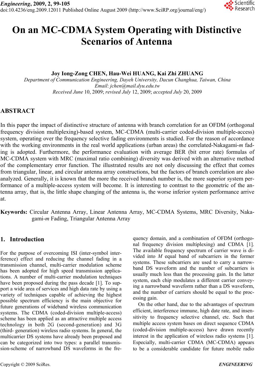 Engineering, 2009, 2, 99-105 doi:10.4236/eng.2009.12011 Published Online August 2009 (http://www.SciRP.org/journal/eng/) Copyright © 2009 SciRes. ENGINEERING 99 On an MC-CDMA System Operating with Distinctive Scenarios of Antenna Joy Iong-Zong CHEN, Hau-Wei HUANG, Kai Zhi ZHUANG Department of Communication Engineering, Dayeh University, Dacun Changhua, Taiwan, China Email: jchen@mail.dyu.edu.tw Received June 10, 2009; revised July 12, 2009; accepted July 20, 2009 ABSTRACT In this paper the impact of distinctive structure of antenna with branch correlation for an OFDM (orthogonal frequency division multiplexing)-based system, MC-CDMA (multi-carrier coded-division multiple-access) system, operating over the frequency selective fading environments is studied. For the reason of accordance with the working environments in the real world applications (urban areas) the correlated-Nakagami-m fad- ing is adopted. Furthermore, the performance evaluation with average BER (bit error rate) formulas of MC-CDMA system with MRC (maximal ratio combining) diversity was derived with an alternative method of the complementary error function. The illustrated results are not only discussing the effect that comes from triangular, linear, and circular antenna array constructions, but the factors of branch correlation are also analyzed. Generally, it is known that the more the received branch number is, the more superior system per- formance of a multiple-access system will become. It is interesting to contrast to the geometric of the an- tenna array, that is, the little shape changing of the antenna is, the worse inferior system performance arrive at. Keywords: Circular Antenna Array, Linear Antenna Array, MC-CDMA Systems, MRC Diversity, Naka- gami-m Fading, Triangular Antenna Array 1. Introduction For the purpose of overcoming ISI (inter-symbol inter- ference) effect and reducing the channel fading in a transmission channel, multi-carrier modulation scheme has been adopted for high speed transmission applica- tions. A number of multi-carrier modulation techniques have been proposed during the pass decade [1]. To sup- port a wide area of services and high data rate by using a variety of techniques capable of achieving the highest possible spectrum efficiency is the main objective for future generations of wideband wireless communication systems. The CDMA (coded-division multiple-access) scheme has been applied as an attractive multiple access technology in both 2G (second-generation) and 3G (third- generation) wireless radio systems. In general, the multicarrier DS systems have already been proposed and can be categorized into two types: a parallel transmis- sion-scheme of narrowband DS waveforms in the fre- quency domain, and a combination of OFDM (orthogo- nal frequency division multiplexing) and CDMA [1]. The available frequency spectrum of carrier wave is di- vided into M equal band of subcarriers in the former systems. These subcarriers are used to carry a narrow- band DS waveform and the number of subcarriers is usually much less than the processing gain. In the latter system, each chip modulates a different carrier convey- ing a narrowband waveform rather than a DS waveform, and the number of carriers should be equal to the proc- essing gain. On the other hand, due to the advantages of spectrum efficient, interference immune, high date rate, and insen- sitivity to frequency selective channel, etc. Such that multiple access system bases on direct sequence CDMA (coded-division multiple-access) have drawn recently interest in the application of wireless radio systems [1]. Especially, multi-carrier CDMA (MC-CDMA) appears to be a considerable candidate for future mobile radio 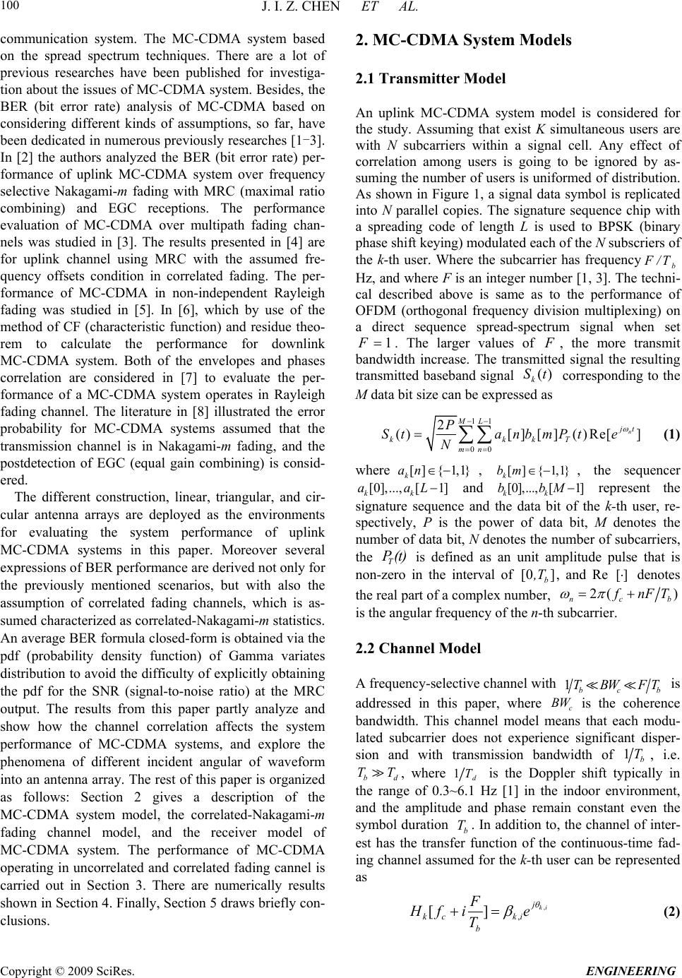 J. I. Z. CHEN ET AL. Copyright © 2009 SciRes. ENGINEERING 100 communication system. The MC-CDMA system based on the spread spectrum techniques. There are a lot of previous researches have been published for investiga- tion about the issues of MC-CDMA system. Besides, the BER (bit error rate) analysis of MC-CDMA based on considering different kinds of assumptions, so far, have been dedicated in numerous previously researches [1-3]. In [2] the authors analyzed the BER (bit error rate) per- formance of uplink MC-CDMA system over frequency selective Nakagami-m fading with MRC (maximal ratio combining) and EGC receptions. The performance evaluation of MC-CDMA over multipath fading chan- nels was studied in [3]. The results presented in [4] are for uplink channel using MRC with the assumed fre- quency offsets condition in correlated fading. The per- formance of MC-CDMA in non-independent Rayleigh fading was studied in [5]. In [6], which by use of the method of CF (characteristic function) and residue theo- rem to calculate the performance for downlink MC-CDMA system. Both of the envelopes and phases correlation are considered in [7] to evaluate the per- formance of a MC-CDMA system operates in Rayleigh fading channel. The literature in [8] illustrated the error probability for MC-CDMA systems assumed that the transmission channel is in Nakagami-m fading, and the postdetection of EGC (equal gain combining) is consid- ered. The different construction, linear, triangular, and cir- cular antenna arrays are deployed as the environments for evaluating the system performance of uplink MC-CDMA systems in this paper. Moreover several expressions of BER performance are derived not only for the previously mentioned scenarios, but with also the assumption of correlated fading channels, which is as- sumed characterized as correlated-Nakagami-m statistics. An average BER formula closed-form is obtained via the pdf (probability density function) of Gamma variates distribution to avoid the difficulty of explicitly obtaining the pdf for the SNR (signal-to-noise ratio) at the MRC output. The results from this paper partly analyze and show how the channel correlation affects the system performance of MC-CDMA systems, and explore the phenomena of different incident angular of waveform into an antenna array. The rest of this paper is organized as follows: Section 2 gives a description of the MC-CDMA system model, the correlated-Nakagami-m fading channel model, and the receiver model of MC-CDMA system. The performance of MC-CDMA operating in uncorrelated and correlated fading cannel is carried out in Section 3. There are numerically results shown in Section 4. Finally, Section 5 draws briefly con- clusions. 2. MC-CDMA System Models 2.1 Transmitter Model An uplink MC-CDMA system model is considered for the study. Assuming that exist K simultaneous users are with N subcarriers within a signal cell. Any effect of correlation among users is going to be ignored by as- suming the number of users is uniformed of distribution. As shown in Figure 1, a signal data symbol is replicated into N parallel copies. The signature sequence chip with a spreading code of length L is used to BPSK (binary phase shift keying) modulated each of the N subscriers of the k-th user. Where the subcarrier has frequencyb F /T Hz, and where F is an integer number [1, 3]. The techni- cal described above is same as to the performance of OFDM (orthogonal frequency division multiplexing) on a direct sequence spread-spectrum signal when set 1 F . The larger values of F , the more transmit bandwidth increase. The transmitted signal the resulting transmitted baseband signal corresponding to the M data bit size can be expressed as ()t k S 11 00 2 ()[][] ()Re[] n ML jt kkkT mn P StanbmPt e N (1) where [] {1,1} k an ..., [1] kk aaL , , the sequencer []{1,1} k bm [0], and represent the signature sequence and the data bit of the k-th user, re- spectively, P is the power of data bit, M denotes the number of data bit, N denotes the number of subcarriers, the T is defined as an unit amplitude pulse that is non-zero in the interval of [0 , and Re [] [0],...,[ kk bb ] b ,T 1]M P(t) denotes the real part of a complex number, 2( ) ncb f nF T is the angular frequency of the n-th subcarrier. 2.2 Channel Model A frequency-selective channel with 1bc b is addressed in this paper, where is the coherence bandwidth. This channel model means that each modu- lated subcarrier does not experience significant disper- sion and with transmission bandwidth of TBWFT c BW 1b T, i.e. , where b TTd1d T is the Doppler shift typically in the range of 0.3~6.1 Hz [1] in the indoor environment, and the amplitude and phase remain constant even the symbol duration b. In addition to, the channel of inter- est has the transfer function of the continuous-time fad- ing channel assumed for the k-th user can be represented as T , , []ki j kc ki b F Hf ie T (2) 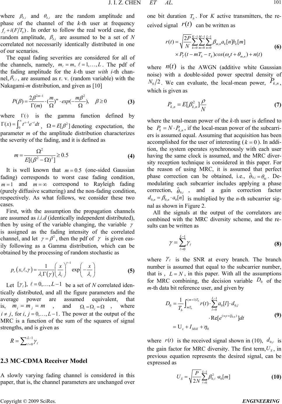 J. I. Z. CHEN ET AL. Copyright © 2009 SciRes. ENGINEERING 101 where ,ki and ,ki are the random amplitude and phase of the channel of the k-th user at frequency () cb f iFT. In order to follow the real world case, the random amplitude, ,ki are assumed to be a set of N correlated not necessarily identically distributed in one of our scenarios. The equal fading severities are considered for all of the channels, namely, . The pdf of the fading amplitude for the k-th user with i-th chan- nel, , 1,,mm L ,k , are assumed as r. v. (random variable) with the Nakagami-m distribution, and given as [10] 21 2 2 ()()(), 0 () m m mm Pexp m (3) where is the gamma function defined by () 1 0 x () t x te dt , 2 [E] denoting expectation, the parameter m of the amplitude distribution characterizes the severity of the fading, and it is defined as 2 22 0.5 [() ] mE (4) It is well known that 0.5m (one-sided Gaussian fading) corresponds to worst case fading condition, and correspond to Rayleigh fading (purely diffusive scattering) and the non-fading condition, respectively. As what follows, we consider these two cases. 1mm First, with the assumption the propagation channels are assumed as i.i.d (identically independent distributed), then by using of the variable changing, the variable is assigned as the fading intensity of the correlated channel, and let 2 , then the pdf of is given eas- ily following as a Gamma distribution, which can be obtained by the processing of random stochastic as 1 1 ,, exp r x x px (5) Let [], 0,,1 L i be a set of N correlated iden- tically distributed, and all the figure parameters and the average power are assumed equivalent, that is, j mm m , and i j , where . The power at the output of the MRC is a function of the sum of the squares of signal strengths, and is given as ,ij for , 0,,1ij L 1 0 L R 2.3 MC-CDMA Receiver Model A slowly varying fading channel is considered in this paper, that is, the channel parameters are unchanged over one bit duration b T ) . For K active transmitters, the re- ceived signal can be written as (rt 111 , 000 , 2 ()[ ][] ()()() KM L mn kk kmn Tbknmn P rtanb m N Pt mTcostnt (6) where is the AWGN (additive white Gaussian noise) with a double-sided power spectral density of ()nt 02N. We can evaluate, the local-mean power, , which is given as ,kn P 2 ,, [] kn kn PE N (7) where the total-mean power of the k-th user is defined to be , kkn P NP , if the local-mean power of the subcarri- ers is assumed equal. Assuming that acquisition has been accomplished for the user of interesting (). In addi- tion, the system operates synchronously with each user having the same clock is assumed, and the MRC diver- sity reception technique is considered in this paper. For the reason of using MRC, it is assumed that perfect phase correction can be obtained, i.e., 0 ii 0k 0, . De- modulating each subcarrier includes applying a phase correction, 0,i , and a gain correction factor 0,0, 0[] nn dan is multiplied by the n-th subcarrier sig- nal as shown in Figure 2. All the signals at the output of the correlators are combined with the MRC diversity scheme, and the re- sults can be written as 1 0 L (8) where is the SNR at every branch. The branch number is assumed that equal to the subcarrier number, that is , L N , in this paper. With all the assumptions for MRC combining, the decision variable of the m-th data bit reference user, and given by 0 D 0,0 1 (1) 00 0 () 0 1() [] Re[ ] U b b l L mT l mT l b wt Q sMAI Drtal T e I 0, d dt (9) where is the received signal shown in (10), is the gain factor for MRC diversity. The first term,, in previous equation represents the desired signal, can be expressed as ()rt 0,i d S U 1 2 0, 0 0 [] 2 L S P Ua N m (10) 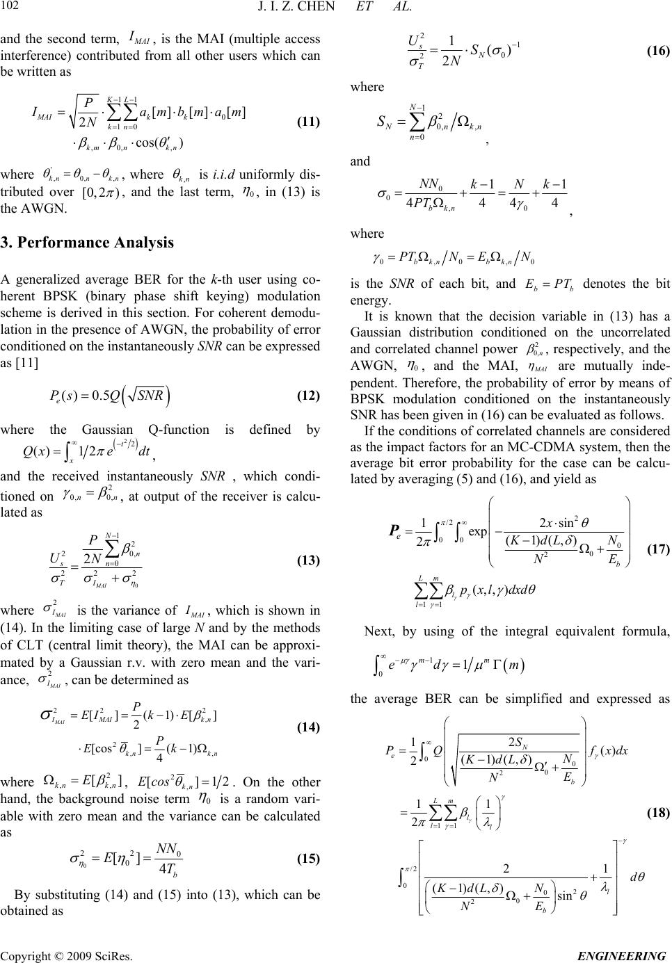 J. I. Z. CHEN ET AL. Copyright © 2009 SciRes. ENGINEERING 102 and the second term, M AI I, is the MAI (multiple access interference) contributed from all other users which can be written as 11 0 10 ,0, , [] [] [] 2 cos( ) KL MAIk k kn km nkn P I ambmam N (11) where ' ,0,knn kn, , where ,kn is i.i.d uniformly dis- tributed over [0,2 ) , and the last term, 0 , in (13) is the AWGN. 3. Performance Analysis A generalized average BER for the k-th user using co- herent BPSK (binary phase shift keying) modulation scheme is derived in this section. For coherent demodu- lation in the presence of AWGN, the probability of error conditioned on the instantaneously SNR can be expressed as [11] () 0.5 e P sQSNR (12) where the Gaussian Q-function is defined by 22 ()12 t x Qxe dt , and the received instantaneously SNR , which condi- tioned on 2 0, 0,nn , at output of the receiver is calcu- lated as 0 1 2 20, 0 22 2 2 MAI N n sn TI P UN (13) where 2 M AI I is the variance of M AI I, which is shown in (14). In the limiting case of large N and by the methods of CLT (central limit theory), the MAI can be approxi- mated by a Gaussian r.v. with zero mean and the vari- ance, 2 M AI I , can be determined as 22 , 2 ,, [] (1)[ 2 [cos]( 1) 4 MAI 2 ] I MAIk n kn kn P EIk E P Ek (14) where 2 ,, [] kn kn E , 2 , [] kn Ecos 12 . On the other hand, the background noise term 0 is a random vari- able with zero mean and the variance can be calculated as 0 22 0 0 []4b NN ET (15) By substituting (14) and (15) into (13), which can be obtained as 2 1 0 2 1() 2 s N T US N (16) where 1 2 0, , 0 N Nn n S kn , and 0 0 ,0 11 444 bkn NN kNk PT 4 , where 0,0,bkn bkn PTNEN0 is the SNR of each bit, and bb E PT denotes the bit energy. It is known that the decision variable in (13) has a Gaussian distribution conditioned on the uncorrelated and correlated channel power 2 0,n , respectively, and the AWGN, 0 , and the MAI, M AI are mutually inde- pendent. Therefore, the probability of error by means of BPSK modulation conditioned on the instantaneously SNR has been given in (16) can be evaluated as follows. If the conditions of correlated channels are considered as the impact factors for an MC-CDMA system, then the average bit error probability for the case can be calcu- lated by averaging (5) and (16), and yield as 2 /2 00 0 0 2 11 12sin exp (1)(,) 2 (,, ) b Lm l l e x N KdL E N pxldxd P (17) Next, by using of the integral equivalent formula, 1 01 mm ed m the average BER can be simplified and expressed as 00 0 2 11 /2 02 0 0 2 2 1() (1)(,) 2 11 2 21 (1)(,) sin N e b Lm l ll l b S P Qf N KdL E N d N KdL EN xdx (18)  J. I. Z. CHEN ET AL. Copyright © 2009 SciRes. ENGINEERING 103 where is given in (7), 1 and 0 are shown in (6) and (22), respectively, the symbol 21 (,;;) F denotes the confluent hyper-geometric function [13], and 0 , fdL N , which represent that the expo- nential MIP (multipath intensity profile) is adopted in this derivation, and the ,1 1 L dLee . 4. Results and Discussions In this section where some of the numerical results for validation of the derived formulas are discussed, for the reason of the impact in the different configuration of antenna array, it is interesting to review the view point of space diversity (antenna diversity) first, the numerical results will be followed up. 4.1. Discussion of Space Diversity It is well known that adopts the diversity scheme is one common mean to overcome the degradation in perform- ance of a wireless communication system due to fading (generally small fading). Generally speaking, the diver- sity reception may be accomplished by a number of techniques. The most common approaches, employed in wireless radio applications, are frequency diversity, time diversity, multipath diversity, path diversity, and antenna diversity. In antenna diversity, also called space diversity, which is divided into classes such as, field component, space, polarization, and angle [14]. Accordingly, the different results from the phenomenon of channel fading will be solved by a lot of different methods. For a multi- ple-access spread-spectrum wireless system, e.g., an 60 60 Signals from Signals from broadside (b) Linear geometric (c) Circular geometric (a) Triangular geometric Figure 1. Three different antenna array geometrics applied in this paper. 0,0 2 2c jft e b Re T 0,1 22(1)/ 2cb jftFtT e b Re T 0, 1 22(1)/ 2cbN jftFNtT e b Re T 0 d 1 d l d spreading weight i ng ()rt Figure 2. The receiver model of an MC-CDMA system. MC-CDMA system, when it is working in the environ- ment suffers from the frequency selective fading, the space diversity is a pretty one mean which is able to be for utilizing to combine with different antenna array in order to overcome the fading problems. In this article, three kinds of antenna constructions, uniform linear with 3-fixed antennas, triangular array with 3-fixed antennas, and circular array with 4-fixed antennas, as applied and depicted in Figure 1, will be co-existed with the receiver, which is shown in Figure 2, of an MC-CDMA system. The effects of correlation generated between different antennas will be taken into account the analysis. There- fore, the depth of correlation will be characterized by eigenvalues, which are calculated from the covariance matrix formed by a given Gaussian branch (antenna) correlation model as [5] 22 ,(/) exp[()(/)/2] ij Cd kijd (19) where , 1,,ij L , denotes the physical distance of two adjacent antennas, and d is the wavelength of incom- ing waveform. It means that the ratio /d is going to be a factor dominates the performance of a wireless radio system while considering the effect of antenna (branch) correlation. The curves with varying /d values shown in Figure 3. Hereafter, the spatial correlation for a circular antenna array geometric investigated in [15] is adopted to verify the accuracy of the derived formulas. Since the Gaussian correlation model is implied in the cases of linear and triangular antenna geometrics men- tioned previously, one of the correlation function,(,)ij are , determined in [15] we Gaussian angle distribution for the incident signal is applied and rewritten as ith th  J. I. Z. CHEN ET AL. Copyright © 2009 SciRes. ENGINEERING 104 2 02 1 2 Re , 2 [( )2 cos(2 (2))] CkC k k ij e JZJZ kd y (20) 2 21 0 2 Im , 2 [2sin((2 1) ( 2))] kC k k mn e JZ k dy (21) where and denote the real part and imaginary part, respectively, Re[ ]Im[ ] 1( 2 erf ) , where is the error function, ()erf indicates the standard deviation of the Gaussian distribution, () n J is the modified Bessel function of the first kind, 0.5 Z 22 12 ZZ C, where 2( l) Z ijd , , ,1ij,...,L represents the mean angle of arrival. Hence, for a given antenna array configuration, the branch correlation depends on the signal incident angle, the antenna height, and the antenna separation. These effects for the system performance will be figured out in sub-section. 4.2. Numerical Results In order to validate the accuracy of our derived formulas -10 -5051015 1E-9 1E-8 1E-7 1E-6 1E-5 1E-4 1E-3 0.01 0.1 1 m=4 m=3 m=2 m=1 BER Eb/N0(dB) L=3 Linear_array N=32 Triangular_array K=10 =0.2 d=8 Figure 3 BER vs SNR with different m values between lin- ear and triangular array. mentioned above and the comparison purpose, the sys- tem performance for both linear and triangular antenna array geometrics are shown in Figure 3 together. It is worthy noting that the system performance always be- come degraded when the system is operating in the tri- angular antenna array. It is well known that the system performance is significantly varied with different separa- tions between transmitter and receiver. The system per- formance for an MC-CDMA system under the circular antenna array with different fading parameter, 2 m is presented in Figure 4. The incident angle of the signal with 0 0 , and are assumed in both figures. It is valuable to mention that the system will stay superior situation when the incident is in small one, this is due to the correlation will become decrease after the incident angle of the propagating waveform related small. 0 45 5. Conclusions In this paper the impact of distinctive structure of an- tenna with branch correlation for an MC-CDMA system, operating over the frequency selective fading environ- ments is studied. The system parameters with the subcar- rier number, correlation coefficients, the branch number, and the exponential MIP are considered for determina- tion the system performance of an MC-CDMA system. The results explicit illustrated that the phenomena of channel correlation and the multipath fading do dominate the performance of MC-CDMA communication systems. However, the most important factors should be the fad- ing parameter of the fading model, and the subcarrier number. Hence it is worthy not only to pay much atten- tion in the consideration of correlation coefficient for channel fading while designing the MC-CDMA systems, but the chosen of designing the scenarios of antenna are important. -10 -50510 15 1E-6 1E-5 1E-4 1E-3 0.01 0.1 1 E b /N 0 (dB) =450 =00 N=8 N=32 L=4 m=2 k=10 =0.5 BER Figure 4. Plots BER vs SNR with different subcarrier num- ber under circular antenna array, and the fading parame- ter is 2m .  J. I. Z. CHEN ET AL. Copyright © 2009 SciRes. ENGINEERING 105 6. References [1] N. Yee, J. P. Linnartz, and G. Fettweis, “Multi-carrier CDMA in indoor wireless radio networks,” IEICE Transactions on Communication, Vol. E77-B, No. 7, pp. 900-904, July 1994. [2] Z. J. Kang and K. Yao, “Performance comparison of MC-CDMA over frequency-selective Nakagami-m and Rayleigh fading channels,” Vehicular Technology Conference, Vol. 6, pp. 4228-4232, September 2004. [3] E. A. Sourour and M. Nakagami, “Performance of or- thogonal multicarrier CDMA in a multipath fading channel,” IEEE Transactions on Communication, Vol. 44, pp. 356-367, March 1996. [4] T. Kim, Y. Kim, J. Park, K. Ko, S. Choi, C. Kang, and D. Hong, “Performance of an MC-CDMA system with frequency offsets in correlated fading,” IEEE Interna- tional Conference on ICC 2000, Vol. 2, pp. 1095-1099, June 2000. [5] J. Park, J. Kim, S. Choi, N. Cho, and D. Hong, “Per- formance of MC-CDMA systems in non-independent Rayleigh fading,” IEEE on ICC’ 99, Vol. 1, pp. 6-10, 506-510, June 1999. [6] Q. R. Shi and M. Latva-aho, “Exact error floor for downlink MC-CDMA with maximal ratio combining in correlated Nakagami fading channels,” 2002 Interna- tional Zurich Seminar on Broadband Communications, pp. 37-1-37-5, February 20, 2002. [7] Q. Shi and M. Latva-aho, “Performance analysis of MC-CDMA in Rayleigh fading channels with corre- lated envelopes and phases,” IEE Proceedings: Com- munication, Vol. 150, No. 3, pp. 214-220, June 2003. [8] Z. Li and M. Latva-aho, “Erroe probability for MC-CDMA in Nakagami-m fading channels using equal gain combining,” IEEE International Conference on ICC 2002, Vol. 1, pp. 227-231, April 28-May 2, 2002. [9] M. S. Alouini, A. Abdi, and M. Kaveth, “Sum of gamma variates and performance of wireless commu- nication systems over Nakagami-m fading channels,” IEEE Transactions on Vehicular Technology, Vol. 50, No. 6, pp. 1471-1480, November 2001. [10] M.Nakagami, “The m-distribution—A general formula of intensity distribution of rapid fading,” Statistic Methods of in Radio Wave Propagation, Pergamon Press, New York, pp. 3-36, 1960. [11] M. Schwartz, W. R. Bennett, and S. Stein, “Communi- cation systems and techniques,” McGraw-Hill, New York, 1966. [12] M. K. Simon and M. S. Alouini, “A unified approach to the performance analysis of digital communication over generalized fading channel,” Proceedings of the IEEE, Vol. 86, pp. 1860-1877, September 1998. [13] I. S. Gradshteyn and I. M. Ryzhik. “Table of integrals, series, and products,” CA: Academic Press, San Diego, 5th Edition, 1994. [14] W. C. Jakes, “Microwave Mobile Communications,” IEEE Press, Piscataway, Jersey, 1974. [15] J. Zhou, S. Sasaki, S. Muramatsu, H. Kikuchi and Y. Onozato, “Saptial correlation for a circular antenna array and its applications in wireless communications,” IEEE Global Telcommunications Conference, Vol. 2, pp. 1108-1113, 2003. |