 Journal of Surface Engineered Materials and Advanced Technology, 2011, 1, 62-72 doi:10.4236/jsemat.2011.12010 Published Online July 2011 (http://www.SciRP.org/journal/jsemat) Copyright © 2011 SciRes. JSEMAT AZ91 Magnesium Alloys: Anodizing of Using Environmental Friendly Electrolyt es N. A. El Mahallawy1, M. A. Shoeib2, M. H. Abouelenain3 1The Design and Production Engineering Department, Faculty of Engineering, Ain Shams Un iversity, Cairo, Egypt; 2Surface Coating Department, Central Metallurgical Research & Development Institute, Helwan, Cairo, Egypt; 3Petroleum Marine Service, Cairo, Egypt. Email: nahed.elmahallawy@guc.edu.eg Received March 14th, 2011; revised May 30th, 2011; accepted Jun e 8th, 2011. ABSTRACT An anodizing process, based on environmental friendly electrolyte solutions has been studied on AZ 91 magnesium al- loys by using three types of electrolytes: the first is based on sodium silicate, the second on sodium hydroxide-boric acid-borax and the third on sodium silicate-potassium hydroxide-sodium carbonate-sodium tetra borate. A pretreat- ment including fluoride activation was applied before the anodizing process. It was found that the anodic film thickness increases as current density or anodizing voltage increases. It is also increased with deposition time until the deposition stops due to the formation of a thick anodic film. Optimization of the anodizing conditions - current density and deposi- tion time - was ma de for each electrolyte. Characterization of anodizing layer was achieved by determination of surface morphology, microstructure, phase analysis, coat thickness, adhesion and corrosion resistance. In all cases, excellent adhesion and corrosion resistance was obtained. A corrosion efficiency ranging from 94% to 97% was reached; the highest value corresponding to the third electrolyte. Keywords: Anodizing, Magnesium AZ91, Corrosion, Characterization, Environmental Friendly Electrolytes 1. Introduction Magnesium and its alloys have received great attention because of their superior properties, such as low density, high specific strength/stiffness, excellent dimensional stability and elec tromagnetic shielding property, superior damping capacity, high creep strength, good machinabil- ity, weldability, high impact resistance, high recyclabili- ty, as well as thermal and electrical conductivities [1,2]. They are used in fields where weight reduction is critical or where particular technical requirements are required such as automotive, aeronautic and aerospace including space station, artificial satellite, space shuttle, nuclear energy, electronic and military industries, together with AVCC (Audio video-Comp uter -Communication) equip- ment, portable tools, supporting goods, etc. [3,4]. How- ever, magnesium and its alloys are highly susceptible to corrosi on esp ecial ly in harsh environmental conditions. Several techniques have been applied in order to im- prove the surface properties of magnesium alloys. Ano- dizing is among the promising techniques for surface protection of Mg alloys; however, most existing anodiz- ing processes use toxic chromate, harmful phosphate or/and fluorides. Therefore, it is still worthy to develop new environmental friendly anodizing processes [5]. In this paper, the anodizing process, based on envi- ronmental friendly electro lyte solutio ns using DC c urrent have been developed to enhance the corrosion resistance of magnesium AZ91alloy. The electrolytes contain none of the chromates, phosphates or fluorides solutions. Op- timization of the process parameters was achieved and the anodizing layer was characterized by its adhesion strength, thicknes s, phase analysis, microstructure, a s well as its corrosion resistance on AZ91 magnesium alloys . 2. Experimental Technique The die-cast Mg alloy AZ91, whose chemical composi- tion is shown in Table 1, was prepared as circular discs of 50 mm diameter and 10 mm thickness. The chemical composition was analyzed by Atomic Emission Spec- troscopy (AES). Anodizing experiments were done by using two group s of c hemic als: che micals for pretreatment and che- micals for anodizing processes. The pretreatment proce- dure used commonly in electroless processes [7], shown in Table 2, was applied. 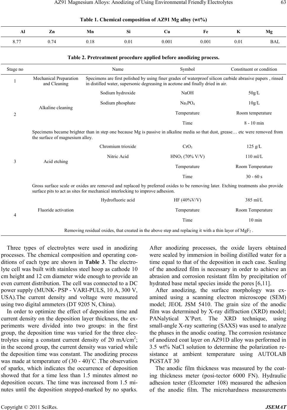 AZ91 Magnesium Alloys: Anodizing of Using Environmental Friendly Electrolytes Copyright © 2011 SciRes. JSEMAT Table 1. Chemical composition of AZ91 Mg alloy (wt%) Al Zn Mn Si Cu Fe K Mg 8.77 0.74 0.18 0.01 0.001 0.001 0.01 BAL Table 2. Pret reatment procedure applied before anodizing process. Stage no Name Symbo l Con stituent or condition 1 Mechanical Preparation and Cl eani ng Specimens are first polished by using finer grades of waterproof sili c on ca rbid e ab ra s i ve pa p ers , rin sed in distilled water, supersoni c degrea sing in acetone and finally dried in air. 2 Alka line cleanin g Sodium hydroxide NaOH 50g/L Sodium phosphate Na3PO4 10g/L Temperature Room t emperature Tim e 8 - 10 min Spec im ens bec am e brigh ter t han in step on e b ecaus e Mg is pas sive i n alk alin e med ia so th at du st, g rease… etc were removed from the surface of magnesium alloy. 3 Acid etching Chromium trioxide CrO3 125 g/L Nitric Acid HNO3 (70% V/V) 110 ml/L Temperature Room Temperature Tim e 30 - 60 s Gross surfac e scale or o xides a re removed a nd rep laced b y preferr ed oxid es to be removing la ter. Etching treatments also provide surface pits to act as sites for m echanical int erlocking to improve adh es ion. 4 Fluoride activation Hydrofluoric acid HF (40%V/V) 385 ml/L Temperature Room Temperature Tim e 10 m in Removing residual oxides, that created in the above step and replacing it with a thin layer of MgF2 . Three types of electrolytes were used in anodizing processes. The chemical composition and operating con- ditions of each type are shown in Table 3. The electro- lyte cell was built with stai nless steel hoop as catho de 10 cm height and 12 cm diameter wide enough to provide an even current distribution. The cell was connected to a DC power supply (MUNK- PSP - VARI-PULS, 10 A, 300 V, USA).The current density and voltage were measured using two digita l ammeter s (DT 9205 N, Chi na). In order to optimize the effect of deposition time and current de nsity on the deposition layer thickness, the ex- periments were divided into two groups: in the first group, the deposition time was varied for the three elec- trolytes using a constant current density of 20 mA/cm2; in the se cond gr oup, the curre nt densi ty was varied while the deposition time was constant. The anodizing process was made at temperature of (30 - 40)˚C .The observation of sparks, which indicates the occurrence of deposition showed that for a time less than 1.5 minutes almost no deposition occurs. The time was increased from 1.5 mi- nutes until the deposition stopped-marked by no sparks. After anodizing processes, the oxide layers obtained were sealed by immersion in bo iling distilled water for a time equal to that of the deposition in each case. Sealing of the anodized film is necessary in order to achieve an abrasion and corrosion resistant film by precipitation of hydrated base metal species inside the pores [6,11]. After anodizing, the surface morphology was ex- amined using a scanning electron microscope (SEM) model; JEOL JSM 5410. The grain size of the anodic film was determined by X-ray diffraction (XRD) model; PANalytical X’Pert. The XRD technique, using s mall -angle X-ray scattering (SAXS) was used to analyze the phases in t he a no d ic co a ting. The corrosion resistance of an odized coat layer on AZ91D alloy was performed in 3.5 wt% NaCl solution to determine the polarization re- sistance at ambient temperature using AUTOLAB PGSTAT 30 The anodic film thickness was measured by the coat- ing thickness meter (posi-tector 6000 FN). Hydraulic adhesion tester (Elcometer 108) measured the adhesion of the anodic film. The microhardness measurements  AZ91 Magnesium Alloys: Anodizing of Using Environmental Friendly Electrolytes Copyright © 2011 SciRes. JSEMAT Table 3. Chemical composition and operating conditions of electrolytes. Electrolyte (1) [8] sodium silicate (Na2SiO2) 122 g/l Temp (30 - 40)˚C Current density 16 mA/cm2 to 31 mA/cm 2 Deposition time (minute) 1.5 to 11 Ele ctro ly te (2) [9] Sodium hydroxide (NaOH) 50.0 g/L Boric acid(H3BO3) 10.0 g/L Borax or hydrous sodium borate (Na2B4O7.10H2O) 20.0 g/ L Temp (30 - 40)˚C Current density 16 mA/c m 2 to 20 mA/cm2 Deposition time (minute) 1.5 to 9 Ele ctro ly te (3) [10] Sodium silicate (Na2SiO3) 50 g/l Pota ss ium hydr o xide (KOH ) 50 g/l Sodium carbonate (Na2CO3) 50g/l Sodium tetra borate (Borax Na2B4O7 ) 30 g/l Temp (30 - 40)˚C Current density 16 mA/cm2 to 31 mA/cm 2 Deposition time (minute) 1.5 to 9 were carried out by the hardness tester model Shimdsu type M, and the surface roughness by Elcometer 223. The microhardness measurements of coat layers were performed on specimens cross-sections using 50-gram load for 15 seconds. 3. Results and Discussion 3.1. Effect of Pretreatment on Surface Morphology Study of the surface morphology after the pretreatment procedure, shown Fig ure 1, indicates the formation of pits, which is expected to improve the adherence of coat layer to the substrate. The use of fluoride activation in the pretreatment is also expected to add a layer of MgF2 which minimizes the effect of local corrosion cells by cre ating an equipotentialized surface [7]. 3.2. Effect o f the Deposition Time on the Coating Thickne ss Figure 2 shows that the coat thickness for the three elec- trolytes incre ases with the depo sition time, rapidly in the first 3 minutes then with a slow rate after 3 to 9 minutes until it levels o ff after 9 minutes. T his behavior is due to the increase in the thickness of the coat layer acting as a barrier to the flow of current, which decreases the rate of oxidation of magnesium. From the results, the optimum deposition time used to obtain maximum coat thickness was 9 minutes for the three electrolytes at the same oper- ating conditions with 20 mA/cm2 current d ensit y. In ge n- eral, the coat thickness was the highest for electrolyte (1) - 42 µm, followed by electrolyte (2) - 32 µm, then elec- trolyte (3)-28 µm. Comparison between the maximum coating thickness obtained in the present work and previous work [8-10] indicates a general agreement, however, difference in values are obtained due to the difference in base metal composition, current density and temperature. For exam- ple, for electrolyte 1, maximum coating layer thickness was 42 µm while in previous work [8] on AZ91, the anodic film was 25 µm at 60 C, 20mA/Cm2 and 9 mi- nutes coating time. The large thickness in the present work is due to the lower anodizing temperature. This explanation is based on previous work [12,13], which  AZ91 Magnesium Alloys: Anodizing of Using Environmental Friendly Electrolytes Copyright © 2011 SciRes. JSEMAT indicates that (a) (b) Figure 1. Surface morpholog y of the AZ91 magnesium alloy (a) before pre-treatment (b) after pre-treatment. Figure 2. Effect of deposition time on coat thickness by using three electrolytes and pre-treatment procedure at te mp. (30 - 40)˚C and constant c urrent dens ity –DC-2 0 mA/cm2. the temperature and coat thickness are inversely propor- tional. 3.3. Effect of Current Density on Coating Thickness The current density is a main electric parameter in ano- dizing. Figure 3 shows the effect of current density on coat thickness for the three types of electrolytes, using a deposition time of 9 minutes (optimum) at a temperature (30 - 40)˚C. With increasing current density, the driving  AZ91 Magnesium Alloys: Anodizing of Using Environmental Friendly Electrolytes Copyright © 2011 SciRes. JSEMAT force for anodizing increases, which enhances the coat development and formation. The thickness increased first Figure 3. Effect of current density on coating thickness by using three electrolytes and constant deposition time at 9 minutes. rapidly up to 20 mA/cm2 then t he rate slowed d own unt il almost no increase in thickness of the deposited oxide layer was obtained. This threshold current density was 25mA/cm2 for electrolyte (1) and (3) and 20 mA/cm2 for electrolyte (2), resulting in coat thickness of 50 µm for electro lyte (1) and 30 µm for electrolytes (2) and(3). For coat development, there are three ways by which anions move to the anode, mainly diffusion, convection and electric migration [14]. The latter being the main one during anodizing. It can be said that as the anodizing layer thickness increases beyond a certain value, the electric migration is suppressed due to the higher resistivi- ty of the formed oxide layer marked by stop of sparking. 3.4. Oxide Formation Mechanism The anodizing process is a dynamic equilibrium of par- tial processes of oxide formation, the others. The me- chanism of anodizing process could be explained disso- lutio n, and oxygen e voluti on. T he d ominance of one p ar- tial process will suppress according to the growth of anodic film, in which the pre-existing film was streng- thened, modified or substituted repeatedly by spark- ing/break- down events. The sparking occurs by the ac- tion of the strong electric field created during anodiza- tion. Anions in the electrolyte first need to arrive at the anode/elec- trolyte interface and then enter into anodic coatings [15]. The general reactions, occurring in the anodizing process for Mg, are as follow: (1) (2) (3) (4) 2 24 2 MgOHSiOMgSiO+→ (5) During the oxidation process, the Mg ions, produced by reaction (1), combine with the OH− in the electrolyte solution to form Mg(OH)2 and Mg2SiO4 (reactions (3) and (5), respectively). Due to the thermal energy from the sparks in the PEO process, the hydroxides change to oxide compounds by the dehydration process, reaction (4). The coating formation processes, reactions (3), (4) and (5) may be promoted by a high concentration of the electrolyte, containing more SiO2 and OH− ions. Based on previous observations during anodizing of AZ 91 magnesium alloy [5], formation and dissolution of oxide/hydroxide films occur simultaneously. The present results indicate that the anodic film growth is dominant up to 20 - 25 mA/cm2, b eyo nd which t he thi ck ness o f th e oxide layer remains almost constant due to the break- down and/or dissolution of this thin film as previously noticed. 3.5. Surface Morphology of Anodic Coat The surface morphology of anodic coat, Figures 4-6, revealed the presence of pores with different shapes and sizes distributed all over the surface. However, the pores are very small and do not have full penetration to the substrate surface. Different pore size and density were observed depending on the electrolyte. Electrolyte (1) created many pores of approximately 7 µm diameter, Figure 4, while electrolyte (2) created a few pores of approximately 1 µm diameter, Figure 5, and electrolyte (3) created a few pores of (2 - 3) µm diameter, Figure 6. These differences in pore diameters result from the dif- ferences of spark behavior and evolution of gases, as in electrolyte (1) the spark was stronger and accompanied with higher evolution of gases compared to electrolytes (2) and (3). Micro cracks are also visible on the coat surface. They are formed due to thermal stresses resulting from rapid cooling of the oxides by the electrolyte acting as a coo- lant. Difference crack sizes are also observed in the coat layer due to the presence of different oxides, with differ- ent shrinkage rates [16,17] depending on the type of electrolyte (see next paragraph), Figures 4-6 . The cracks are probably formed in week regions, where the localized film layers were destroyed prior to other regions. However, new anodizing products formed in/around the broken regions rapidly and intensively so that the existing microdefects were filled up or mended by the fresh products. This is clear from the occurrence of cracks on the surface but not reaching the depth.  AZ91 Magnesium Alloys: Anodizing of Using Environmental Friendly Electrolytes Copyright © 2011 SciRes. JSEMAT 3.6. Phase Analys is in Coat Layer Using XRD and EDX X-ray diffraction patterns of the specimen anodized by Figure 4. SEM morphology show ing the coat surface using electro lyte (1).  AZ91 Magnesium Alloys: Anodizing of Using Environmental Friendly Electrolytes Copyright © 2011 SciRes. JSEMAT Figure 5. SEM morphology showing the coat thickness using electrolyte (2). Figure 6. SEM morphology showing the coat surface using electrolyte (3).  Current Distortion Evaluation in Traction 4Q Constant Switching Frequency Converters Copyright © 2011 SciRes. JSEMAT using electrolyte (1), Figure 7, indicate that the domi- nating phase is MgO, followed by smaller amounts of SiO2 and M g as s hown i n Table 4 , while in case o f elec- trolyte(2), the dominating phase is MgO, Mg and B2O3. For electrolyte (3), the dominating phase is MgO, fol- lowed by SiO2, Mg and Mg2SiO4. The occurrences of these phases indicate that the substrate and the electro lyte both contrib ute in forming the coat layer. The EDX analysis across the anodic coat layer, Table 5, indicates that the percentage of oxygen and silicon decreases from the surface towards the substrate (zone III > zone II > zone I). This indicates that the coat layer acts as a barrier to decrease the rate of oxidation of magne- sium. It was found previo usly [18 ] that when a r elatively thick coating was established, an excessive oxygen evo- lution is observed. This could explain the increase in oxygen at the exp ense of the Mg on the outer l ayer. 3.7. Microstructure of the Coat Layers and Crystal Size The cross-section view of the coat layers for all three electrolytes, Figure 8, s hows that anod ized coating films are relatively uniform in thic kness and that the pores are present but do not completely extend to the base metal. Pores result from the generation of sparks and evolution of gases from the hydrolysis of water [16]. These pores are relatively uniform in distri bution. The crystal size of the anodic coat determined by X-ray diffraction (XRD), indicate that all crystal phases are in the nano scale with sizes 4 to 5 nm, Table 6. This means that the three electrolytes result in almost similar crystal size, as the MgO is the dominating phase in all coats. 3.8. Coat Adhesion An excellent adhesion exceeding 18 MPa between the anodic film and the substrate was found for all speci- mens. This value is larger than for electroless nickel plating on anodized magnesium alloy (about 11 MPa) [19]. This adhesion is enhanced by the formation of pits formed by the pretreatment procedure, which increased the surface roughness and contributed to increased adhe- sion of the coat layer as reported by Adachi et al. [20]. In additions, the analysis of the obtained anodic film layers showed that they contain (Mg - MgO- Mg2SiO4). This indicates that the metallic substrate has diffused into coating layer, resulting in further enhancement of the adhesion. 3.9. Surface Roughness Ten surface roughness measurements were taken on the surface of the specimens and the results in Figure 9 in- dicate that the surface roughness ranges from 13 µm to Figure 7. XRD spectra of the anodic coatings by using electrolyte (1), [temp . (30 - 40)oC, deposition time 9 min and current density 31 mA/cm2]. Table 4 Phases present in coating layer using the different electrolytes. Compound name Chem ical formu la Score Percentage (wt%) Electrolyte (1) 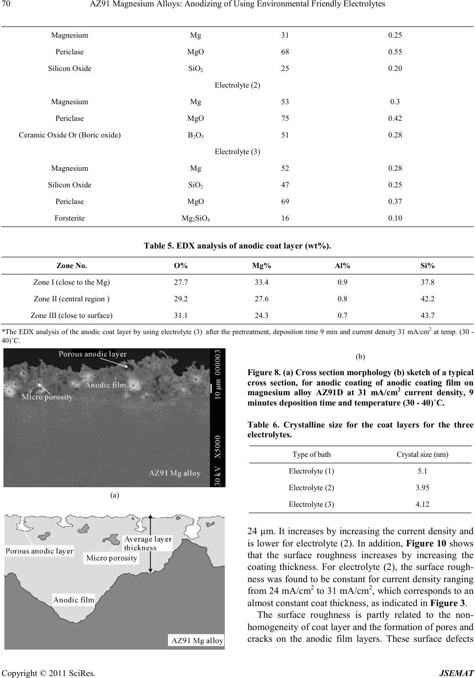 AZ91 Magnesium Alloys: Anodizing of Using Environmental Friendly Electrolytes Copyright © 2011 SciRes. JSEMAT Magnesium Mg 31 0.25 Periclase MgO 68 0.55 Sili con Oxide SiO2 25 0.20 Electrolyte (2) Magnesium Mg 53 0.3 Periclase MgO 75 0.42 Ceramic Ox ide Or (Boric oxide) B2O3 51 0.28 Electrolyte (3) Magnesium Mg 52 0.28 Sili con Oxide SiO2 47 0.25 Periclase MgO 69 0.37 Forsterite Mg2SiO4 16 0.10 Table 5. EDX analys is of anodic c oat layer (w t%). Zone No. O% Mg% Al% Si% Zone I (close to the Mg) 27.7 33.4 0.9 37.8 Zone I I (central region ) 29.2 27.6 0.8 42.2 Zone III (close to surface) 31.1 24.3 0.7 43.7 *The EDX analysis of the anodic coat layer by using electrolyte ()3 after th e pretreatment, deposition time 9 min and current density 31 mA/cm2 at temp. (30 - 40)˚C. (a) (b) Figure 8. (a) Cross section morphology (b) sketch of a typical cross section, for anodic coating of anodic coating film on magnesium alloy AZ91D at 31 mA/cm2 current density, 9 minutes depo sition time and temperature (30 - 40)˚C. Table 6. Crystalline size for the coat layers for the three electrolyt es. Type of bath Crystal size (nm) Electrolyte (1) 5.1 Electrolyte (2) 3.95 Electrolyte (3) 4.12 24 µm. It increases by increasing the current density and is lower for electro lyte (2). I n addition, Figure 10 shows that the surface roughness increases by increasing the coating thickness. For electrolyte (2), the surface rough- ness was found to be constant for curr ent d ens ity r angi n g fr o m 2 4 mA/cm2 to 31 mA/cm2, which corresponds to an almost constant coat thickness, as indicated in Fig ure 3. The surface roughness is partly related to the non- homogeneity of coat layer and the formation of pores and cracks on the anodic film layers. These surface defects 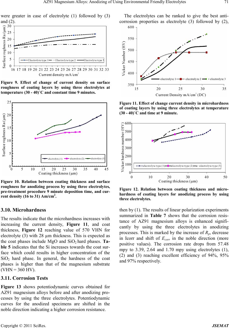 AZ91 Magnesium Alloys: Anodizing of Using Environmental Friendly Electrolytes Copyright © 2011 SciRes. JSEMAT were greater in case of electrolyte (1) followed by (3) and (2). Figure 9. Effect of change of current density on surface roughness of coating layers by using three electrolytes at temperature (30 - 40)˚C and constant time 9 minutes. Figure 10. Relation between coating thickness and surface roughness for anodizing process by using three electrolytes, pre-treatment procedure 9 minute deposition time, and cur- rent density (16 to 31) Am/cm2. 3.10. Mic rohardness The results indicate that the microhardness increases with increasing the current density, Figure 11, and coat thickness, Fig ure 12 reaching value of 570 VHN for electrolyte (3) with 28 µm thickness. This is expected as the coat phases include MgO and SiO2 hard phases. Ta- ble 5 indicates that the Si increases towards the coat sur- face which could results in higher concentration of the SiO2 hard phase. In general, the hardness of the coat phases is higher than that of the magnesium substrate (VHN = 360 HV). 3.11. Corrosion Tests Figure 13 shows potentiodynamic curves obtained for AZ91 magnesium alloys before and after anodizing pro- cesses by using the three electrolytes. Potentiodynamic curves for the anodized specimens are shifted in the noble direc tion indi cating a higher corrosion resi sta nce. The electrolytes can be ranked to give the best anti- corrosion properties as electrolyte (3) followed by (2), Figure 11. Effect of change current density in microhardness of coating layers by using three electrolytes at temperature (30 - 40)˚C and time at 9 minute. Figure 12. Relation between coating thickness and micro- hardness of coating layers for anodizing process by using three electrolytes. then by (1). The results of linear polarization experiments summarized in Table 7 shows that the corrosion resis- tance of AZ91 magnesium alloys is enhanced signifi- cantly by using the three electrolytes in anodizing processes. T his is marked by the increase of Rp, decrease in Icorr and shift of Ecorr in the noble direction (more positive values). The corrosion rate drops from 57.48 mpy to 3.39, 2.64 and 1.70 mpy using electrolytes (1), (2) and (3) reaching excellent efficiency of 94%, 95% and 97% respectively. 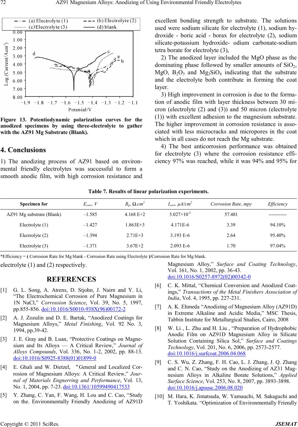 AZ91 Magnesium Alloys: Anodizing of Using Environmental Friendly Electrolytes Copyright © 2011 SciRes. JSEMAT Figure 13. Potentiodynamic polarization curves for the anodized specimens by using three-electrolyte to gather with the AZ91 Mg Substrate (Blank). 4. Conclusions 1) The anodizing process of AZ91 based on environ- mental friendly electrolytes was successful to form a smooth anodic film, with high corrosion resistance and excellent bonding strength to substrate. The solutions used were sodium silicate for electrolyte (1), sodium hy- droxide - boric acid - borax for electrolyte (2), sodium silicate-potassium hydroxide- odium carbonate-sodium tetra bora te for e le c trolyte (3), 2) The anodized layer included the MgO phase as the dominating phase followed by smaller amounts of SiO2, MgO, B2O3 and Mg2SiO4 indicating that the substrate and the electrolyte both contribute in forming the coat layer . 3) High i mprove ment in corr osion is due to the forma- tion of anodic film with layer thickness between 30 mi- cron (electrolyte (2) and (3)) and 50 micron (electrolyte (1)) with excellent adhesion to the magnesium substrate. The higher improvement in corrosion resistance is asso- ciated with less microcracks and micropores in the coat which in all cases do not reach the Mg substrate. 4) The best anticorrosion performance was obtained for electrolyte (3) where the corrosion resistance effi- cienc y 97% was reached, while it was 94% and 95% for Table 7. Result s of linear polarization experiments. Specimen for Ecorr, V Rp, Ω.cm2 Icorr, µA/cm2 Corrosion Rat e, mpy Efficiency AZ91 Mg substrate (Blank) –1.585 4.168 E+2 5.027×10⁻⁵ 57.481 ----------- Electrolyte (1) –1.427 1.863E+3 4.171E-6 3.39 94.10% Electrolyte (2) –1.394 2.71E+3 3.19 3 E-6 2.64 95.40% Electrolyte (3) –1.371 3.67E+2 2.09 3 E-6 1.70 97.04% *Efficiency = ( Corrosion Rate for Mg blank - Cor rosion Rate using Electrolyte )/C orrosion Rat e for Mg blank. electrolyte (1) and (2) respectively. REFERENCES [1] G. L. Song, A. Atrens, D. Stjohn, J. Nairn and Y. Li, “The Electrochemical Corrosion of Pure Magnesium in 1N NaCl,” Corrossion Science, Vol. 39, No. 5, 1997, pp.855-856. doi:10.1016/S0010-938X(96)00172-2 [2] A. J. Zozulin and D. E. Bartak, “Ano dized Coatings for Magnesium Alloys,” Metal Fin ishing, Vol . 92 No. 3, 1994, pp .39-42. [3] J. E. Gray and B. Luan, “Protective Coatings on Magne- sium and Its Alloys — A Critical Review,” Journal of Alloys Compounds, Vol. 336, No. 1-2, 2002, pp. 88-13. doi:10.1016/S0925-8388(01)01899-0 [4] E. Ghali and W. Dietzel, “General and Localized Cor- rosion of Magnesium Alloys: A Critical Review,” Jour- nal of Materials Engnerring and Performance, Vol. 13, No. 1, 2004, pp. 7-23. doi:10.1361/10599490417533 [5] Y. Zhang, C. Yan, F. Wang, H. Lou and C. Cao, “Study on the. Environmentally Friendly Anodizing of AZ91D Magnesium Alloy,” Surface and Coating Technology, Vol. 161, No. 1, 2002, pp. 36-43. doi:10.1016/S0257-8972(02)00342-0 [6] C. K. Mittal, “Chemical Conversion and Anodized Coat- ings,” Transactions of the Metal Finishers Association of India, V ol. 4, 19 95, pp. 22 7-231. [7] A. K. Ehmeda “Anodizing of Magnesium Alloy (AZ91D) in Extreme Alkaline and Acidic Media,” MSC Thesis, Tabbin Institute for Metallurgical Studies, Cairo, 2008 [8] W. Li , L. Zhu and H. Liu , “Preparation of Hydrophobic Anodic Film on AZ91D Magnesium Alloy in Silicate Solution Containing Silica Sol,” Surface and Coatings Technology, Vol. 20 1, No. 6, 2006, pp. 2573-2577. doi:10.1016/j.surfcoat.2006.04.068 [9] C. S. Wu, Z. Zhang, F. H. Cao, L. J. Zhang, J. Q. Zhang and C. N. Cao, “Study on the Anodizing of AZ31 Mag- nesium Alloys in Alkaline Borate Solutions,” Applied Surface Science, Vol. 253, No. 8, 2007, pp. 389 3-3898. doi:10.1016/j.apsusc.2006.08.020 [10] M. Hara, K. Ji matsuda, W. Yamau chi, M. Sakaguchi an d T. Yoshi kata. “Optimization of Environmentally Friendly 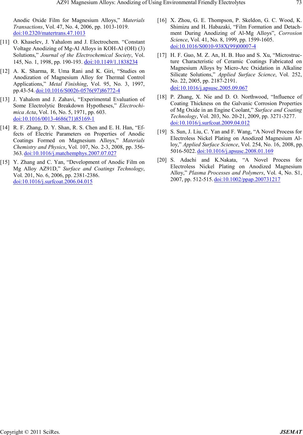 AZ91 Magnesium Alloys: Anodizing of Using Environmental Friendly Electrolytes Copyright © 2011 SciRes. JSEMAT Anodic Oxide Film for Magnesium Alloys,” Materials Transactions, Vol. 47, No. 4, 20 0 6, pp. 1013-1019. doi:10.2320/matertrans.47.1013 [11] O. Khaselev, J. Yahalom and J. Electrochem. “Constant Voltage Anodizing of Mg -Al Allo ys in KOH-Al (OH) (3) Solutions,” Journal of the Electrochemical Society, Vol. 145, No. 1, 1998, pp. 190-193. doi:10.1149/1.1838234 [12] A. K. Sharma, R. Uma Rani and K. Giri, “Studies on Anodization of Magnesium Alloy for Thermal Control Applications,” Metal Finishing, Vol. 95, No. 3, 1997, pp.43-54. doi:10.1016/S0026-0576(97)86772-4 [13] J. Yahalom and J. Zahavi, “Experimental Evaluation of Some Electrolytic Breakdown Hypotheses,” Electrochi- mica Acta, Vol. 16, No. 5, 197 1, pp. 603. doi:10.1016/0013-4686(71)85169-1 [14] R. F . Zhang, D. Y. Shan, R. S. Chen and E. H. Han, “Ef- fects of Electric Parameters on Properties of Anodic Coatings Formed on Magnesium Alloys,” Materials Chemistry and Physics, Vol. 107, No. 2 -3, 20 08, pp. 356- 363. doi:10.1016/j.matchemphys.2007.07.027 [15] Y. Zhang and C. Yan, “Development of Anodic Film on Mg Alloy AZ91D,” Surface and Coatings Technology, Vol. 201, No. 6, 2006, pp. 2381-2386. doi:10.1016/j.surfcoat.2006.04.015 [16] X. Zhou, G. E. Thompson, P. Skeldon, G. C. Wood, K. Shimizu and H. Habazaki, “Film Formation and Detach- ment During Anodizing of Al-Mg Alloys”, Corrosion Scien ce, Vol. 41, No. 8, 199 9, pp . 1599-1605. doi:10.1016/S0010-938X(99)00007-4 [17] H. F. Guo, M. Z. An, H. B. Huo and S. Xu, “Microstruc- ture Characteristic of Ceramic Coatings Fabricated on Magnesium Alloys by Micro-Arc Oxidation in Alkaline Silicate Solutions,” Applied Surface Science, Vol. 252, No. 22, 2005, pp. 2187-2191. doi:10.1016/j.apsusc.2005.09.067 [18] P. Zhang, X. Nie and D. O. Northwood, “Influence of Coating Thickness on the Galvanic Corrosion Properties of Mg Oxid e in an Engine Coolant,” Surface and Coating Technology, Vol. 20 3, No. 20-21, 2009, pp. 32 71-3277. doi:10.1016/j.surfcoat.2009.04.012 [19] S. Sun, J. Liu, C. Y an and F. Wan g, “A Novel P r ocess for Electroless Nickel Plating on Anodized Magnesium Al- loy,” Applied Surface Science, Vol. 254, No. 16, 2008, pp. 5016-5022. doi:10.1016/j.apsusc.2008.01.169 [20] S. Adachi and K.Nakata, “A Novel Process for Electroless Nickel Plating on Anodized Magnesium Alloy,” Plasma Processes and Poly mers, Vol. 4, No. S1, 2007, pp . 512-515. doi:10.1002/ppap.200731217
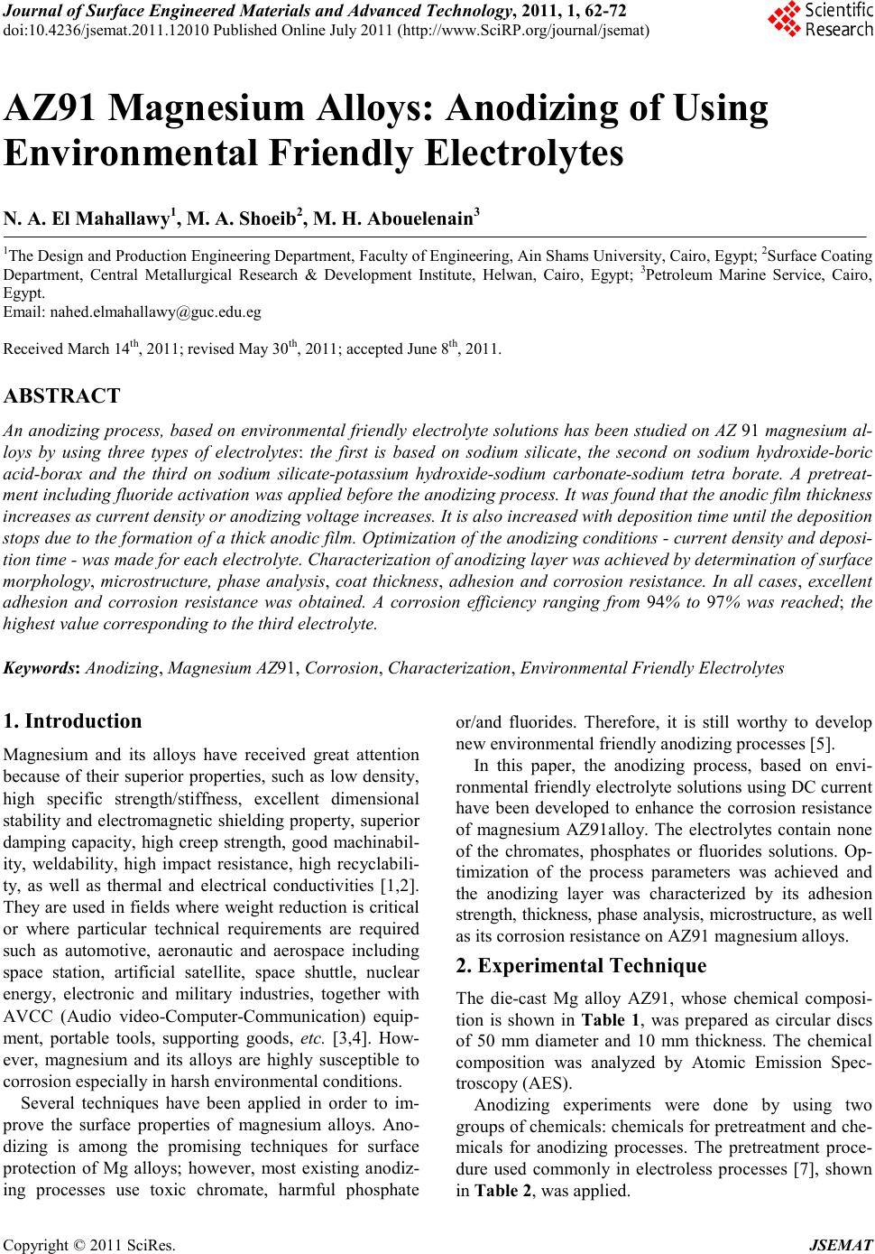
|