World Journal of Engineering and Technology
Vol.03 No.03(2015), Article ID:60511,7 pages
10.4236/wjet.2015.33C025
A New Type of Bridge, Mobilebridge® to Super-Quickly Recover a Bridge
Ichiro Ario, Yuki Chikahiro
Department of Civil & Environmental Engineering, Hiroshima University, Higashi-Hiroshima, Japan
Email: mario@hiroshima-u.ac.jp


Received 30 August 2015; accepted 15 October 2015; published 22 October 2015

ABSTRACT
Many natural disasters cause not only critical situations for facilities and resident’s residents’ life, but also significant damage to economy. It is obvious that quick rescue action must be undertaken and that there are many problems due to the occurrence of secondary disasters at rescue worksite. Basing Based on the previous study of deployable structures and the concept of the multi-folding micro-structures, we propose a new type of foldable bridge in form of scissor structure called the Mobile-bridge™. In this paper, we discuss the vehicle passing test performed on the real-scale Mobile-bridge in order to evaluate its mechanical characteristics and application limits. Moreover, we verified the compatibility between the result of calculations and experiments by means of theoretical modelling. The results show that it is sufficient to treat the load as equivalent nodal forces applied at the joints without including the stiffness of the deck.
Keywords:
Mobilebridge™, Scissors Type of Emergency Bridge, Deplyable Bridge, Vehicle Loadings

1. Introduction
In recent years, the world has seen many kinds of natural disasters such as earthquakes, floods and tsunamis. In a case of our floods investigation, many residents suffered from bridge and road damage caused by very strong rains along several river branches in the northern Kyushu of Japan in 2012. Therefore, bridge designers or engineers have to consider how to rebuild the damaged infrastructure, and how to build new types of rescue systems, which can be quickly deployed, because rescue time is very important when trying to save lives in an emergency. Based on the previous study of the previous study of deployable structures and the concept of the multi-folding micro-structures [1]-[4], we propose a new type of emergency bridge-the Mobilebridge™ (hereinafter-called MB) which can expand and store for concrete disaster recovery system [5]. Although the upper and lower chord members are main elements which resist the bending moment in a general truss bridge, MB can be built by using a scissors mechanism for a bridge formation and resist to the sectional force in spite of lacking the one member [6]-[9]. Scissors structure which is the basis of the MB is typical for deployable structures which provide good storage and transportation performance. This structural form combines the members in the shape of X. The joint which connects the members of scissors is a pin-junction in form of a flexible hinge, and the pin joining sections called a “pivot” which exists in the central portion of a scissors member intersect. This kind of scissors type bridge, provides several advantages: 1) even if there are few members for constructing, deployment and storage work are quickly, 2) assembling, transportation and disassembling is easy 3) it has high deployment performance because the scissors structure can deploy and store all units by one control force,. In this paper, we discuss a vehicle loading test performed on the real-scaled Mobile Bridge (called MB1.0) in order to evaluate its mechanical characteristics and application limits. Moreover, we verify the compatibility between the result of analysis, and experiments by means of theoretical approach.
2. Outline of the Real-Scaled Mobilebridge
The schematic view of the experimental, two-unit scissors model for a real scale mobile bridge (called as MB1.0) is shown in Figure 1. When deployment starts from the stored state, the members are sloped gradually until the full span is reached. Moreover, because the deck is sated in MB1.0, the deck works with member as deployment progresses.
In the final stage of expansion the scissors deployment angle is 60 degrees. The total length of the span is 7.0 m and the height of the bridge is 2.0 m. The total weight of the bridge including structural parts such as main members, shafts, and pins is 8.4 kN. The aluminum alloy components are made of the three-chamber hollow section, which uses A6N01 material, is used for the main member, the plastic bending moment is 20.1 kNm, and the ultimate bending strength is 39.9 kNm. The deck on which vehicles travel (called the aluminum alloy deck, hereafter) consists of A6063 extrusion sections. Only the portion of the aluminum alloy deck on which wheel loads act was constructed, because of weight saving. Moreover, the deployment action aims at shortening the construction time by uniting and interlocking the scissors member and the aluminum alloy deck. The properties of the A6N01 material are: E = 61.0 GPa, σB = 198.8 MPa, and σy = 180.0 MPa, while for the A6063 material E = 68.0 GPa, σB = 150.0 MPa, and σy = 110.0 MPa.
3. Theory of Scissors Mechanism
3.1. Mechanics of a Unit Scissors Structure
A Free Body Diagram (called FBD) for a unit of scissors structure is shown in Figure 2. When the length of the members is L0 and the angle of inclination is θ, the sectional length λ and height 2 h are L0sinθ = λ and L0cosθ = 2 h. So, the construction and storage of such a structure can be shown by the angle θ. This unit scissors structure

Figure 1.The stretching behavior of MB1.0.
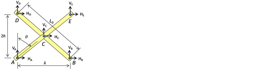
Figure 2.FBD of a unit.
can be designed by using the equation of equilibrium. The equation of equilibrium concerning each the external force VA − VE and HA − HE is given as two expressions,
 (1)
(1)
 (2)
(2)
Looking at the members AE and BD that intersect as shown in Figure 3, it is obtained that the two equilibrium equations of moments occur at Point C as follows.
 (3)
(3)
 (4)
(4)
Let us consider the case of cantilever model which is pinned support for point A and point D. It is possible to use the matrix by arranging the four calculated equilibrium Equations (1)-(4) as shown in Equation (5).
 (5)
(5)
Similarly, we can get equilibrium as Equation (6) in the simple beam model which is pinned support for point A and point B,
![]() (6)
(6)
From the above results, unknown reaction forces can be obtained by considering the loading condition and the boundary condition for these.
3.2. Mechanics of a Scissors Structure in the Consideration of Deck
Next, let us consider the mechanical model when adding the deck to the fundamental theory of the scissors structure, as discussed in the previous section. The unit scissors model with the deck is shown in Figure 4(a), and the FBD, which is made of the unit scissors and each independent deck, is shown in the Figure 4(b). Figure 4(a) shows the whole of structure with moving load such as a vehicle. A vehicle passes over the deck between nodes A and B. According to the wheel load, the reaction forces on the supports occur in the deck, as shown in Figure 4(b). The reaction force which arose in the deck is transmitted to the main member of a unit scissors as an external force P1 and P2. Because the wheel load transmitted from the deck changes with wheel positions, it is thought that the stress distribution which occurs for the scissors member and the deck changes depending on the positions of the vehicles.
![]()
Figure 3. Continuity conditions of each member.
![]()
![]() (a) (b)
(a) (b)
Figure 4. FBD of a unit scissors structure with deck. (a) Whole system; (b) FBD of the deck.
4. Experimental Evaluation of the Load-Carrying Capacity of the Aluminium Alloy Deck
This section describes the ultimate strength test for deck and its results in order to check the safety of the aluminum alloy deck under vehicle loading.
4.1. Outline of the Aluminum Alloy Deck
The aluminum alloy deck with a vehicle traveling is shown in Figure 5. The length of the deck is 3200 mm and the width of the deck is 500 mm. The type of material is A6063-T5. The deck is formed by welding two types of hollow extrusions, one with a width of 200 mm and the other with a width of 100 mm. The weight of one panel is 490 N.
4.2. Experiment Conditions
The aluminum alloy deck was constructed of a steel pipe of φ = 20 mm which was pin-fixed at both ends. The loading plate, which supports a tire contact area, uses 175 mm × 175 mm steel plate and the rubber board according to guidelines of Eurocode for bridge design.
4.3. Experimental Results
The load-displacement curve at the loading point is shown in Figure 6. The horizontal axis shows the displacement of the head part of the loading machine, and the vertical axis shows the increment of the load. Below P = 1 kN, the load was increased by 0.2 kN, and above P = 1 kN, the load was increased by 1 kN until P = 14 kN. After reaching P = 14 kN, the load was removed and residual displacement and strain of the aluminum alloy deck was checked. Then, the displacement was increased by δ = 10 mm. The aluminum alloy deck had lost a load bearing capacity at the value of load of 15.1 kN and the experiment ended.
4.4. Distribution of the Stress in the Central Cross-Section Position
The stress distribution in the central section corresponding to the force of P = 4.5 kN, 5.0 kN, and 5.5 kN is depicted in Figure 7 The stress values (MPa) are shown on the vertical axis, and the distances from the neutral axis (mm) are shown on the horizontal axis. Moreover, the line of σy = ±110 MPa shows the yield stress of the material A-6063. From Figure 7, we can see that the undersurface surrendered for the first time at the value of force of P = 5.0 kN and the serviceability limits load of the deck was equal to 5.0 kN. The maximum bending moment was Mmax = 28.7 kNm in the central part of the aluminum deck, and this value corresponds to yielded bending moment for the deck.
5. The Vehicle Loading Test Using MB1.0
This section describes the outlines and results of the vehicles loading test using MB1.0. Moreover, experimental results are compared with theory of scissors and FE analysis.
5.1. Vehicles Outline
Two kinds of vehicles, Honda STREET and Nissan AD van, were used for the vehicles loading test. The
![]()
Figure 5. The schematic diagram of deck.
![]()
Figure 6. Load-displacement curve.
![]()
Figure 7. Distribution of the strain values at central section of the deck.
STREET’s (Full length × full width × overall height) was (3195 mm × 1395 mm × 1870 mm), while the AD van’s (Full length × full width × overall height) was (4370 mm × 1895 mm × 1510 mm). The wheel base of the STREET was 1900 mm and the total weight of the STREET including the driver is 9.6 kN distributed 5.2 kN of front axis and 4.4 kN of rear axis. The wheel base of AD van was 2535 mm and the total weight of the AD van including the driver is 13.8 kN distributed 7.5 kN of front axis and 6.3 kN of rear axis.
5.2. Vehicles Stop Position and Loading Condition
From Table 1 it can be seen that the measurements were performed five times. When the front wheel, the axle (defined here as the intermediate part of the front and the rear wheel), and the rear wheel came to a specific point and stopped, the value of the strain was measured. The stop positions were the center of the deck for the first unit scissors and the central part of MB1.0. One case corresponds to the STREET, which is a light vehicle, and the other case is the AD van, which is a standard-sized car. In the loading Case 2, the additional weight was added from Case 1 was the backseat of the vehicles.
5.3. Results of the Experiment
Figure 8(a) and Figure 8(b) shows the strain distribution in case when the vehicle was located in the center of the bridge. Figure 8(a) portrays a mountain-shaped member which starts from supports, and Figure 8(b) pays attention to the member which is in a free state (the target colored in red). Moreover, a blue mark in the figure shows the position of the strain gage. It can be seen that the experimental and analytical values are smaller than maxima admissible strain (=2000 με) for loading vehicles until 13.8 kN. A maximum strain of about 500 με occurred in member intersection part, so the safety ratio was relatively large from the yield strain.
From Figure 8(a), we can confirm that the maximum strain of 500 με was measured at the circumference of the pivot of the first unit, and the minimum strain was measured by the circumference of the pivot of the second unit. Because the distribution of the strain was almost equal in the compression and the tension area, it turned out that the influence of the bending moment was great. Although accuracy had variations in comparison with the analytical results, the maximum value was distributed within 10%.
Figure 8(b) shows that strains hardly occurred at the member, which was in an end-free state (maximal value around ±10 με). It turned out that the analytical results also showed the same tendency. The bending moment did not act on the member, but the strain had increased with a little axial tension.
![]()
Table 1.Loading conditions.
![]()
![]() (a) (b)
(a) (b)
Figure 8. Distribution of strain in the center of MB1.0. (a) Member ends-supports; (b) Member ends-free.
6. Conclusions
The points which became clear from this research are followed as:
Through the bending test, it was proved that the load-carrying capacity of the aluminum deck was sufficient for vehicles passing over.
In the static loading experiment of MB1.0 it was found that measured strains caused by vehicles loading are consistent with previously obtained analytical values (difference less than 10%).
With a maximum loading weight of 13.8 kN, the main member and decks are within allowable stress, and it turned out that the vehicles about 10 kN could pass safely on MB1.0.
Acknowledgements
We appreciated that all manufacture of cradles were supported by Star Light Metal Industry Co., Ltd., Akashin Corporation, Sankyotateyama Inc., Japan Construction Method and Machinery Research Institute and FSC Co. Ltd which is supported by a grant.
Cite this paper
Ichiro Ario,Yuki Chikahiro, (2015) A New Type of Bridge, Mobilebridge® to Super-Quickly Recover a Bridge. World Journal of Engineering and Technology,03,170-176. doi: 10.4236/wjet.2015.33C025
References
- 1. Holnicki-Szulc, J., Pawlowski, P. and Wiklo, M. (2003) High-Performance Impact Absorbing Materials—The Concept Design Tools and Applications. Smart Materials and Structures, 12, 461-467. http://dx.doi.org/10.1088/0964-1726/12/3/317
- 2. Ario, I. and Watson, A. (2007) Structural Stability of Multi-Folding Structures with Contact Problem. Int. J. Non- Linear Mechanics, 324, 263-282.
- 3. Ario, I. and Nakazawa, M. (2010) Nonlinear Dynamics Behavior of Multi-Folding Microstructure Systems Based on Origami Skill. Int. J. Non-Linear Mechanics, 45, 337-347. http://dx.doi.org/10.1016/j.ijnonlinmec.2009.11.010
- 4. Ario, I. and Kim, H.A. (2006) Michell Problem for the Stiffness Formation of Structural Design in 3 Dimensional Space. Proc. of Optimizational Symposium in JSME, 7, 179-184.
- 5. Ario, I. (2006) Structure with the Expanding and Folding Equipment as a Patent (No.2006-037668).
- 6. Ario, I., Tanaka, Y., Nakazawa, M., Furukawa, Y. and Chikahiro, Y. (2009) Research and Development of the High-Efficiently Foldable Structure (Analysis). Proc. of Space Structure and Material Symposium in JAXA, 25, 104-107 (in Japanese).
- 7. Tanaka, Y., Ario, I., Nakazawa, M., Furukawa, Y. and Chikahiro, Y. (2009) Research and Development of the High-Efficiently Foldable Structure (Experiment). Proc. of Space Structure and Material Symposium in JAXA, 25, 108-111 (in Japanese).
- 8. Ario, I., Tanaka, Y., Nakazawa, M., Furukawa, Y. and Chikahiro, Y. (2010) Development of the Prototype of a New Emergency Bridge Based on the Concept of Optimized Structure. Journal of Structural Engineering, JSCE, 64A, 1-12 (in Japanese).
- 9. Ario, I., Furukawa, Y., Tanaka, Y., Chikahiro, Y., Matumoto, S., Nakazawa, M., Tanikura, I. and Ono, S. (2010) Dynamic Vibration of a Prototype Deployable Bridge Based on MFM. The Proceedings of the 9th World Congress on Computational Mechanics and 4th Asian Pacific Congress on Computational Mechanics WCCM/APCOM.