Paper Menu >>
Journal Menu >>
 I. J. Communications, Network and System Sciences. 2008; 1: 1-103 Published Online February 2008 in SciRes (http://www.SRPublishing.org/journal/ijcns/). Copyright © 2008 SciRes. I. J. Communications, Network and System Sciences. 2008; 1:1-103 Any Resource Sharing via HWN* Routing Chong SHEN, Susan REA, Dirk PESCH Centre for Adaptive Wireless Systems, Department of Electronic Engineering Cork Institute of Technology Ireland E-mail: {chong.shen, susan.rea, dirk.pesch}@cit.ie Abstract In this paper we present an adaptive distributed cross-layer routing algorithm (ADCR) for hybrid wireless network with dedicated relay stations (HWN*). To support versatile multimedia communication for Mobile Terminals (MTs), the HWN* integrates a cellular network, an ad hoc network and fixed relay nodes (RNs). A MT may borrow cellular data channels that are available thousands mile away via secure multi-hop RNs, where RNs are placed at flexible locations in the network. The MT can also communicate with each other or access internet ubiquitously. We discuss cross media access and network layers routing issues. The ADCR establishes routing paths across RNs or cellular network while providing appropriate QoS (quality of service). Through simulation, we verify the routing performance benefits of HWN* over conventional cellular systems and other hybrid network frameworks. It is anticipated that the simulation results reported in this paper will serve as a guideline for research based on distributed source routing involving heterogeneous wireless technologies. Keywords: Routing, QoS, Cross-layer, Traffic Management, HWN* 1. Introduction The recent widespread uptake of high-data rate and multimedia services has led to a shift in how cellular networks are being used. This is motivating wireless providers to develop innovative infrastructure and accompanying routing and radio access algorithms. Due to the small size of the cells of micro cellular networks and the uneven nature of the time varying spatial distribution [1], network performance metrics such as overall throughput, Mobile Terminal (MT) throughput, call blocking probability, handover rate, end-to-end delay, etc. are not sufficient for today’s wireless network where more ad hoc features are being introduced. The traffic in heterogeneous environments is a mixture of real-time packets with widely varying support on Quality of Service (QoS) levels. Recently, Channel Access Scheduling (CAS), Medium Access Control (MAC) and distributed routing schemes were investigated for Mobile Ad Hoc Networks (MANETs) with scenarios involving military networks, emergency services, and inexpensive deployment of sensor networks [2]. But these are energy constrained networks with limitations on capacity and QoS support since as the ad hoc network topologies can rapidly change. To effectively manage problems stated above, we propose to combine the advantages of different networks so that the MTs can utilise an optimised MANET or the Base Station Oriented Network (BSON) and packet relay Figure 1. The hybrid wireless network with fixed relay stations and IP network services. Figure 1 presents our Hybrid Wireless Network with Relay Nodes (HWN*) connected to the Internet Protocol (IP) networks where relay nodes (RNs) compose a mesh like structure through RN gateways, while Base Stations (BSs) are connected to the IP networks via switches. Other than the improvement of downlink power efficiency, the primary goal of the RN incorporation in HWN* is to provide uniform coverage and support the hybrid network relay. Two MTs may communicate directly, or through an intermediate node. This node can 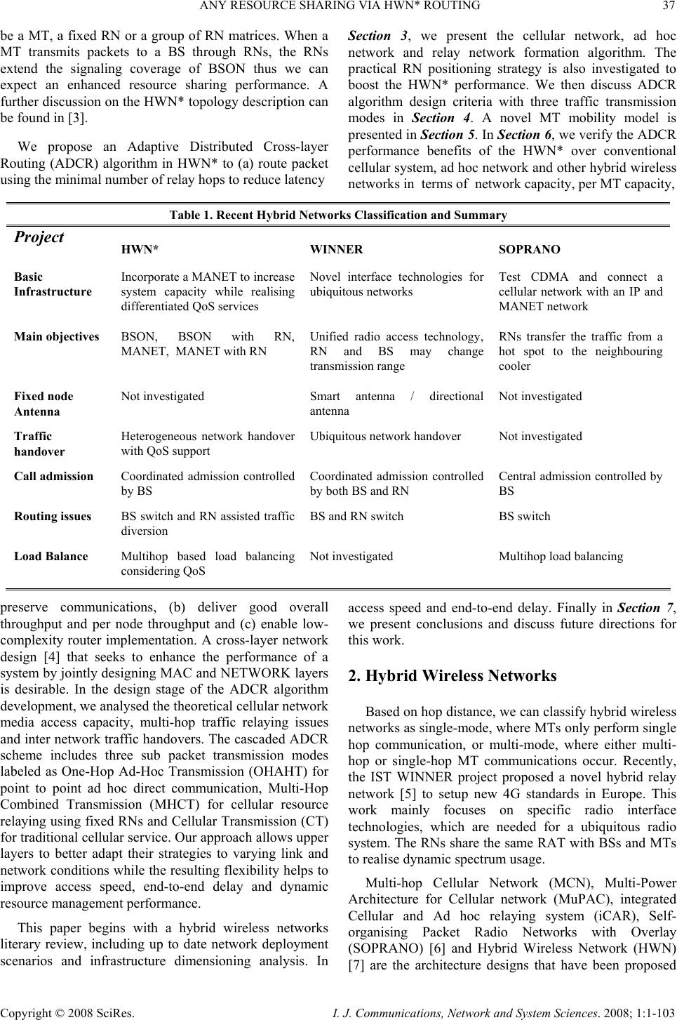 ANY RESOURCE SHARING VIA HWN* ROUTING 37 Copyright © 2008 SciRes. I. J. Communications, Network and System Sciences. 2008; 1:1-103 be a MT, a fixed RN or a group of RN matrices. When a MT transmits packets to a BS through RNs, the RNs extend the signaling coverage of BSON thus we can expect an enhanced resource sharing performance. A further discussion on the HWN* topology description can be found in [3]. We propose an Adaptive Distributed Cross-layer Routing (ADCR) algorithm in HWN* to (a) route packet using the minimal number of relay hops to reduce latency preserve communications, (b) deliver good overall throughput and per node throughput and (c) enable low- complexity router implementation. A cross-layer network design [4] that seeks to enhance the performance of a system by jointly designing MAC and NETWORK layers is desirable. In the design stage of the ADCR algorithm development, we analysed the theoretical cellular network media access capacity, multi-hop traffic relaying issues and inter network traffic handovers. The cascaded ADCR scheme includes three sub packet transmission modes labeled as One-Hop Ad-Hoc Transmission (OHAHT) for point to point ad hoc direct communication, Multi-Hop Combined Transmission (MHCT) for cellular resource relaying using fixed RNs and Cellular Transmission (CT) for traditional cellular service. Our approach allows upper layers to better adapt their strategies to varying link and network conditions while the resulting flexibility helps to improve access speed, end-to-end delay and dynamic resource management performance. This paper begins with a hybrid wireless networks literary review, including up to date network deployment scenarios and infrastructure dimensioning analysis. In Section 3, we present the cellular network, ad hoc network and relay network formation algorithm. The practical RN positioning strategy is also investigated to boost the HWN* performance. We then discuss ADCR algorithm design criteria with three traffic transmission modes in Section 4. A novel MT mobility model is presented in Section 5. In Section 6, we verify the ADCR performance benefits of the HWN* over conventional cellular system, ad hoc network and other hybrid wireless networks in terms of network capacity, per MT capacity, access speed and end-to-end delay. Finally in Section 7, we present conclusions and discuss future directions for this work. 2. Hybrid Wireless Networks Based on hop distance, we can classify hybrid wireless networks as single-mode, where MTs only perform single hop communication, or multi-mode, where either multi- hop or single-hop MT communications occur. Recently, the IST WINNER project proposed a novel hybrid relay network [5] to setup new 4G standards in Europe. This work mainly focuses on specific radio interface technologies, which are needed for a ubiquitous radio system. The RNs share the same RAT with BSs and MTs to realise dynamic spectrum usage. Multi-hop Cellular Network (MCN), Multi-Power Architecture for Cellular network (MuPAC), integrated Cellular and Ad hoc relaying system (iCAR), Self- organising Packet Radio Networks with Overlay (SOPRANO) [6] and Hybrid Wireless Network (HWN) [7] are the architecture designs that have been proposed Table 1. Recent Hybrid Networks Classification and Summary Project HWN* WINNER SOPRANO Basic Infrastructure Incorporate a MANET to increase system capacity while realising differentiated QoS services Novel interface technologies for ubiquitous networks Test CDMA and connect a cellular network with an IP and MANET network Main objectives BSON, BSON with RN, MANET, MANET with RN Unified radio access technology, RN and BS may change transmission range RNs transfer the traffic from a hot spot to the neighbouring cooler Fixed node Antenna Not investigated Smart antenna / directional antenna Not investigated Traffic handover Heterogeneous network handover with QoS support Ubiquitous network handover Not investigated Call admission Coordinated admission controlled by BS Coordinated admission controlled by both BS and RN Central admission controlled by BS Routing issues BS switch and RN assisted traffic diversion BS and RN switch BS switch Load Balance Multihop based load balancing considering QoS Not investigated Multihop load balancing  38 C. SHEN ET AL. Copyright © 2008 SciRes. I. J. Communications, Network and System Sciences. 2008; 1:1-103 for hybrid networks. The iCAR is derived from existing cellular networks and enable the network to achieve theoretical capacity through adaptive traffic load balancing. Excessive bandwidth in surrounding cells can be borrowed for the congested cell through RNs with primary, secondary and cascaded orders. The SOPRANO is a scalable architecture that assumes the use of asynchronous Code Division Multiple Access (CDMA) with spreading codes to support high data rate internet & multimedia traffic. It is similar to iCAR other than IP network support and cross network connection methods. The HWN, without RN support, requires Global Positioning System (GPS) capability to extract geographical location. Each cell operates either in cellular structures or ad hoc structures depending on the MTs topology information from the GPS. Table 1 presents the main features for the HWN*, WINNER and SOPRANO architectures. A comparison of the iCar, MuPAC, HWN and MCN can be found in [8]. Table 2 identifies the technologies used and the features considered for each of the four HWN* communication structures. This table specifies the physical layer mode; media access method, spectrum usage, mobility characteristics and data rate. Time Duplex Division (TDD) is implemented on all four modes: BSON, MANET, RN supported BSON and RN supported MANET. Typical physical layer parameters are used [9]. The log-normal standard deviation σ is set as 10 dB, shadowing correlation distance s χ is set to 50 m, and the mean SIR value d r is set to 17 dB. The default energy mode provided by OMNET++ [10] is implemented, specifically, for a 250m transmission range the transmit power used is 0.282W. The transmit power used for a transmission range of d is proportional to4 d. For the MANET and RN supported MANET, we implemented the CSMA/CA Distributed Coordination Function (DCF) of the IEEE 802.11 standard. The air interface can be adapted for TDD/CDMA of 3GPP as described in [11], where multiple data rates are achieved by using various spreading codes. In Time Division Multiplex Access (TDMA) cellular systems, when an MT is involved in a call admission or handover process in a congested cell, but is not able to find an admission channel or alternative channel, respectively, the data transmission will be terminated. For example, consider a scenario in Figure 2 where MT A is Figure 2. Multi-Hop Combined Transmission Example of cellular resource relaying using fixed RNs currently connected to MT B and is moving out of Cell 1 into Cell 6. A request for a BS handover will be sent as soon as the power level by MT A goes below a certain threshold, its trajectory is indicated by the red line. A successful handover will take place within a few hundred milliseconds depending on speed before the received power from BSs reaches an unacceptable level. When MT A arrives in Cell 6, if the congestion persists for a period of time during which the MT moves farther away from the other neighbouring cell border, thus causing the Table 2 HWN* Four Communication Structures BS cellular network Ad hoc network RN supported cellular network RN supported MANET Physical layer Time division duplex Time division duplexTime division duplex Time division duplex Media access layer TDMA CSMA/CA TDMA CSMA/CA Spectrum regulation Licensed Unlicensed Proposed to use same spectrum as cellular network Proposed to use same spectrum as cellular network Mobility speed Low, Medium and High Low Low, Medium and High Low and Medium Transmission data rate Low, Medium and High Low Low, Medium and High Low and Medium  ANY RESOURCE SHARING VIA HWN* ROUTING 39 Copyright © 2008 SciRes. I. J. Communications, Network and System Sciences. 2008; 1:1-103 received power level from BS A to fall below the acceptable level, handover will fail and the call will be permanently terminated. However in MHCT mode of HWN*, the data session does not have to be dropped even though the congestion in Cell 6 persists. For example, when MT A moves into the congested Cell 6, apart from trying cellular connections, it also associates itself with a RN using ad hoc frequencies, then the RN may continue the data session with any BS in the network via the multi-hop relaying structure and the relaying path can be also extended to the area with no cellular coverage. Since the ultimate goal of this framework is to improve the resource sharing performance in terms of data admission, traffic handover and routing optimization, in addition, OHAHT of point-to-point ad hoc communications is added to the routing strategy to further balance traffic load while sharing media resources. The analytical as well as simulation results we experienced have proven that inter-network traffic management can significantly improve the grade of service, reduce the traffic blocking probability, while maintaining the individual MT QoS. The spectrum for each RN could be also allocated dynamically. Multiple non-interfering relay frequencies operate in parallel through the use of intelligent radios. The spectrum where a RN operates can be leased for a limited time depending on the network status. The spectrum on which it is operating is reclaimed when network performance improves. For example, two RNs operating on non-interfering spectrums form a network relay link with multiple orthogonal bands. Multiple nodes within range of each other may also transmit simultaneously on different channels without relying on a media access protocol or distributed scheduling algorithm to resolve contention. Although the large scale deployment of dual-interfaced RNs could be costly, the use of RNs extends the BSON service range, optimizes cell capacity, minimizes transmit power, covers shadowed areas, supports inter network load balancing and supports MANET routing. Theoretically, both the HWN* system capacity and the transport capacity per MT, when compared to a cellular network, should be improved because the RNs provide relay capability as the substitution of a poor quality single-hop wireless link with a better-quality link being encouraged whenever possible. Also a higher end-to-end data rate could be obtained if a MT had two simultaneously communicating interfaces. Using three scaling approaches proposed in [12], we can implement simulation dimensioning and estimate how many RNs should be deployed when the number of MTs changes. The three parameters are the number of RNs m, the number of MTs n and the system capacity C. The asymptotic scaling for the per user throughput as n becomes large is: nnm log/≤ (1) The per user throughput is of the ordernnC log/ and can be realised by allowing only ad hoc communications which does not necessarily need RN support, when: nnmnn log/log/ ≤≤ (2) The order for the per user throughput is nCm / therefore the total additional bandwidth provided by m RNs is effectively shared among n MTs. Finally, when: mnn ≤log/ (3) the order of the per user throughput is only nC log/ which implies that further investments in relay nodes will not lead to an improvement in throughput and bandwidth optimization. 3. HWN* Formation Algorithm In this section we present the basis for our HWN* fixed RN placement plan and related formation algorithm. The positioning and formation scheme are addressed where RNs operate in the same ad hoc frequency band. Various plans have already been proposed to select sites for fixed RNs, the solutions depend on the varied network performance objectives. The network spectral efficiency was taken by [13] as the objective to optimize RN positioning. For HWN* we adopt a bandwidth oriented criterion to investigate the proper RN positioning, the RN positioning is formulated as a constrained optimization problem, of which the goal is to maximize the overall network throughput and per node throughput so that 95% of MTs are better served with guaranteed quality than by the conventional cellular network without relaying. By imposing such a constraint we can improve the performance for MTs at disadvantaged locations and enlarge network dimensioning and help deliver a more uniform communication experience. In searching for the proper RN locations, [13] made the assumption that the quality on the links connecting BS and RN is always better than the link between RN to from RN. Therefore the authors stated that this assumption can be satisfied by establishing Line of Sight (LOS) links between the BS and RN or by designing links that enhance the antenna gains. But the former solution imposes extra difficulty on network planning, while the latter complicates the transceiver design. Therefore, it is of importance to investigate the RN positioning with limited change on existing radio technologies to save the infrastructure cost. When considering pre-engineered RN deployment, it  40 C. SHEN ET AL. Copyright © 2008 SciRes. I. J. Communications, Network and System Sciences. 2008; 1:1-103 is well known from planar geometry that to cover a two dimensional district with equal sized circles, the best possible packing solution can be obtained by surrounding each circle by six circles as shown in Figure 3. But to have connections between the RNs, we need an overlap between relay cells. We therefore consider a situation where the location of the RNs is pre-computed and the best deployment strategy is chosen. The deployments shown in Figure 3 are two examples of such pre- engineered approach with a specific number of RNs in HWN*. The first deployment tries to cover the entire area, without considering MT mobility and service requirement. The second one tries to cover densely populated regions of MTs near the edge of the cell. Our MT mobility model is based on a city layout that consists of n probability based attractor points that MTs will move towards. Figure 3. Pre-engineered placement of relay nodes We propose to form the relay network of HWN* in two stages, which are Association and Route identification. At the former stage, each MT begins a searching process to associate itself with one or more RNs based on Signal-to-Interference Ratio (SIR). If the BS has spectrum available for one or more RNs, this information is broadcast over the cellular control channels so all nodes within the cell receive it simultaneously. The transmission radius of a node on the relay network is small compared to the cellular coverage. Thus, a RN only connected to a group of MTs and group members of a RN usually overlap with other RN's group members. To select a serving RN, reduce computation complexity and isolate groups, every MT with multiple membership broadcasts a neighbour advertisement (NADV) message with a Time- To-Live (TTL) value. The NADV message contains the identification of the source node and its received signal quality from different RNs. When a node receives NADV message back from multiple RNs, it compares various signal qualities. The RN with the best SIR is chosen as the serving RN and connections with other RNs are terminated. In stage two, if required, MTs join the relay network by forming a path through serving RN using MHCT transmission mode. We consider several methods, which will be described in the next section to overcome high contention or overload at the serving RN, which may occur if several MTs attempt to join the relay network simultaneously. The MHCT uses a modified version of label routing as the main strategy to find the path from the MT via RNs to BS. When an intermediate RN forwards a route request (RREQ) message, it appends its identification and its distance from the BS to the message. Therefore, the serving RN can learn of the nodes involved in the relay path. 4. Adaptive Distributed Cross-layer Routing The heterogeneous network media resources are shared by multiple traffic classes. Service classes that deliver QoS to applications have priority over others that do not. In such a network, routing decisions for high priority QoS sessions can affect what resources are available for lower priority traffic. Poor route selection can result in congestion for, or even starvation of, lower priority traffic. Many studies [14] have focused on routing algorithms that optimise the network throughput for individual service classes, minimise call blocking rate and improve per-session throughput. Little effort has been devoted to routing algorithms that address interclass resource sharing. But the fact is routing in a multi-class network is not as simple as selecting an “optimal” path for each flow, assuming that the traffic class of this flow is the only service class in the network. Such an “optimal” path can adversely affect the congestion condition of flows in other traffic classes. For example, in a network that supports both QoS traffic requiring bandwidth guarantees and best-effort traffic, which resources are available to best-effort traffic depends on how QoS flows are routed. QoS flows can consume all the bandwidth on certain links, thus creating congestion for, or even starvation of best effort sessions. Statically partitioning the link resources can result in low network throughput if the traffic mix changes over time. Thus, a mechanism that dynamically distributes link resources across traffic classes based on the current load conditions in each traffic class is critical for performance. By proposing a cascaded Adaptive Distributed Cross- layer Routing (ADCR) for HWN*, we discourage applications from using any route that is heavily loaded with low priority traffic. Traditional routing strategies that use global state information are not considered. Problems associated with maintaining global state information and the staleness of such information are avoided by having individual MTs infer the network states based on route discovery statistics collected locally, and perform traffic routing using this localised view of the network QoS state. Each application, categorised by service class with the choice of three possible transmission modes, maintains a set of candidate paths to each possible destination and routes flows along these paths. The selection of the candidate paths is a key issue in localised routing and has a considerable impact on how the ADCR performs. The high priority traffic is given high priority in accessing comparatively expensive cellular resource, while low priority traffic tries to access  ANY RESOURCE SHARING VIA HWN* ROUTING 41 Copyright © 2008 SciRes. I. J. Communications, Network and System Sciences. 2008; 1:1-103 low cost ad hoc resource. Per MT bandwidth is used as the only metric for route local statistics collection since it is one of the most important metrics in QoS routing, furthermore, important metrics such as end-to-end delay, jitter can be expressed as a function of the bandwidth. We first divide all traffic sessions into three simple service classes to fairly share spectrum between end user and provider equipment, further reduce the cost implementation, monitoring and management. The three service classes are: z High profile users (HPUs) z Normal profile users (NPUs) z Low profile users (LPUs) The HPUs have the highest access priority among the three communication modes in HWN* and traffic admission of NPUS and LPUs are considered based on current HPUs sessions. The NPUs are configured to have a higher probability than LPUs in terms of resource acquisition and this probability is decided by an Association Level (AL) set. In the case of network congestion, CT mode may temporarily become unavailable to NPUs when HPUs are not fully accommodated, while LPUs sessions may be only granted MHCT and OHAHT mode access to mitigate network congestion, reduce transmission delay and improve per MT throughput. A MT locally links each application with a service class based on particular QoS requirement. The choices are flexible as one subscriber may link business voice calls with the HPUs class and Voice over IP (VOIP) calls to the LPUs class. Another subscriber may link all voice and data services to HPUs class when moving at high speed and then change them to the LPUs class when walking on the street. For the purpose of simulation evaluation of the HWN* applications are temporarily fixed to specific classes. For example, real time collaboration, wireless gaming, and geographic real time datacast applications are associated with the HPUs class. Interactive multimedia, media telephony and rich data applications are linked to the NPUs class. Lightweight browsing, LAN access and file exchange applications are classed as LPUs. As HPUs are liable to require more channels than NPUs and LPUs, applications such as large volumes of file exchanges are not suitable for the ad hoc structures. Secondly, as radio resource management on fixed RNs directly affects the performance of the media access layer and network layer we adopt a policy based management approach and two policies are proposed to realise effective packet transmission. We define: The RN has the right to reserve QoS guaranteed free channels for packet transmission and it maintains a status table that's refers to be other RNs and it provides information on change busy conditions or relay failure. The purpose of bandwidth reservation is to let RNs that receive the relaying discovery command check if they can provide the bandwidth required for the connection. Meanwhile, to decrease queuing delay, high profile traffic should be given higher priority than low profile traffic. Thus, the routing packets and content packets for high profile applications have less waiting time in queues. The other way to raise priority is that the packets related to a high profile have shorter back-off time to increase the probability of early medium access. To more accurately guarantee queuing delay and to avoid having high profile traffic being influenced by other data traffic, we place a limitation on queues. For example, if the transmission time of LPUs exceeds the starting time of HPUs, the transmission of LPUs is suspended. As for the status table maintenance, information flooding is restricted to a limited scope. Once a positive acknowledgment message is confirmed by a requesting RN, the relay paths will not be changed unless resource contention happens. Given the fact that maintaining global RNs channel status in each RN slows down RN response time, we only require each RN update neighbouring RNs’ information, periodically. The transmission model defines the methods that nodes employ for communicating with one another. For ADCR based equipment, several commands are defined as: 1) ACK/ACCEPT/REJECT/REJHO for the message delivery acknowledgment, packet acceptance, packet rejection and after rejection handover request. 2) SEARCH/SETUP/DATA/BREAK for destination node finding, new connection establishment, packet delivery and connection teardown. 3) MOS for MT to choose adaptive transmission mode. 4) FAIL used to acknowledge any failure on RN or MT. 5) LREQ to request a label during the routing. The label is a short, fixed-length identifier. Multiple labels can identify a path or connection from the source MT to the destination MT. The structure of a label message contains flag, label, cost and TTL. 6) LREP to request a label replay during the label routing in MHCT model. Time-sensitive multimedia applications have restrictions on end-to-end transmission delay, while FTP data transfers need a minimum guarantee on packet losses. Further actions such as channel transfer and re-routing are required before service termination. The routing algorithms in HWN* should allow subscribers seamlessly move without dropping their communications and considers differentiated QoS issues, for example, the QoS guarantee for HPUs require that they agree to pay more  42 C. SHEN ET AL. Copyright © 2008 SciRes. I. J. Communications, Network and System Sciences. 2008; 1:1-103 than NPUs and LPUs. The cascaded ADCR scheme includes three sub packet transmission models, which are the OHAHT for point-to- point ad hoc communications, the MHCT for cellular resource relaying using fixed RNs and the CT for traditional cellular service, as illustrated in Figure 4 We further define the HPU has having the highest priority to access any packet transmission models, in the order of CT, MHCT then OHAHT. However, due to the high priority of premium traffic, the global network behaviour as a consequence of this service class, including routing and scheduling of premium packets, may impose significant influences on traffic of other classes as we explained in a previous section. These negative influences, which could degrade the performance of low-priority classes with respect to some important metrics such as the packet loss probability and the packet delay, are often called the inter-class effects. To reduce the inter-class effects, the premium-class routing algorithm must be carefully selected, must work correctly under the hop-by-hop routing paradigm, and minimize the congestion resulting from the traffic of premium classes over the network. We also proposed mechanisms for load balancing of high- priority traffic on DiffServ networks. The Association Level (AL) calculation was proposed to differentiate between user classes. The AL is a set of parameters monitoring channel availabilities, an AL that scores higher than the threshold means that the channels are already occupied by ongoing sessions. Our extensive simulations clearly demonstrated that the proposed methods distribute the premium bandwidth requirements more efficiently over the whole network. We also present corresponding computerised process of MT’s association with a serving BS and RN, and simplified ADCR algorithm with three transmission models in Figure 4. 4.1. One-Hop Ad-Hoc Transmission In this model, the requesting MT first broadcasts SEARCH messages to every node in its transmission range including its associated RN and BS. For example, MT A in Figure 4 broadcasts SEARCH messages, if the destination MT B is within its transmission range and there is no ad hoc based media contention between MT A and MT B, MT B can respond to MT A with an ACK message. Once MT A confirms the acknowledgement, it starts a connection SETUP session immediately. MT A continues transmitting directly until the SIR falls to a certain level, where traffic re-routing or handover process will be initiated. 4.2. Multi-Hop Combined Transmission The multi-hop combined transmission model involves RNs acting as intermediate nodes for message relaying. Figure 4 shows the connection setup process for communication between MT A and MT B via the RN infrastructure. MT A first broadcasts SEARCH messages to every node to find MT B. After the SEARCH session, MT A may find that the cellular resources can be Figure 4. ADCR transmission  ANY RESOURCE SHARING VIA HWN* ROUTING 43 Copyright © 2008 SciRes. I. J. Communications, Network and System Sciences. 2008; 1:1-103 borrowed through RNs by receiving three ACK messages from the serving BS of MT B, RNs and the MT B. The positive acknowledgement requires MT B to send an ACK to its serving BS, then the serving BS sends an ACK to the RN infrastructure and finally the RNs feedback the ACK to MT A. Once the positive ACK is confirmed, the MT A starts a connection SETUP from MT A to RN, then RN to BS, and finally BS to MT B. The DATA transmission process follows the same packet delivery route, and further route discovery is prohibited to reduce the signaling overhead. MT A continues transmitting directly until the SIR falls to certain level, where traffic re-routing or a handover process will be to setup, configure, and maintain a path between two MTs. Media resources are largely saved when compared to other traditional routing algorithms, where paths are initiated. Different from MANET nodes, which have limited energy and processor resources, protocols and algorithms running on the RNs can have a high level of efficiency with reasonable complexity. We introduce the label routing concept [15] in MHCT. The connectionless label routing is a distributed routing protocol that is able maintained regularly. The path from source node works as a tunnel identified by multiple labels, which requires information from both the media access layer and NETWORK layer. With label routing, intermediate RNs can provide fast and efficient forwarding without checking the Internet Protocol (IP) address and accessing a large routing table in the memory of the host RN. In order to find a path to the destination MT, the source MT creates a LREQ message in which the packet contains IDs, sequence number and service class of the source MT. This packet also contains a broadcast ID and a hop count that is initialized to zero. All RNs that receive this message will increment the hop count. If a RN does not have any information about the destination node, it will record the neighbour’s ID where the first copy of LREQ is from and send this LREQ to its neighbours. LREQs from the same node with the same broadcast ID will not be processed more than once. Figure 5 gives an example of label routing in MHCT. In this example, there are eight nodes with duplex connection link. The MT A first creates a LREQ message and sends it out to its associated RN. Figure 5 illustrates the propagation of LREQ across the RNs and the reverse path at every RN. The reverse path entry is created for the transmission of the reserved label for this path. This label is embedded in the label reply message LREP. The reserve path entry will be maintained long enough for the LREQ to traverse the path and for RNs to send a LREP to the source MT. Once a path is found in the relay structure, the source MT will check the sequence number (SEQ) of the destination MT in the current path in order to avoid old path information. It should be at least as great as the value entry in the LREQ. Otherwise the existing path in the table will be discarded. If LREQ SEQSEQ ≥, it will also check in the current path whether the QoS requested by the source MT has been satisfied. If not, this request will be discarded. If the Figure 5. Label Routing illustration  44 C. SHEN ET AL. Copyright © 2008 SciRes. I. J. Communications, Network and System Sciences. 2008; 1:1-103 source MT still can not find the destination MT B, MT A will increment the hop count in the LREQ by one and then broadcast it to its neighbors. Any duplicated LREQ with same source node ID and same broadcast ID will be discarded. Normally relay based label routing should have a maximum hop count. However, there is no energy constraints and node motilities issues in our relay infrastructure, thus theoretically any hop count threshold can be possible. We specify the hop court in LREQ as not being larger than 10 as a simulation limitation to avoid computation complexity and if the sender of a LREQ does not receive the reply message, each node only re- sends the LREQ once for each connection request. The RN only creates a LREP with the total hop count of this path if hop count, sequence number, and path QoS are all acceptable, the new sequence number of the destination MT is the largest one between SEQ and LREQ SEQ , the best QoS, and a label from its label pool. Then this LREP will be sent back to the source MT along the reverse path entry. The third plot in Figure 5 shows the propagation of the LREP along the reserve paths. Note that both RN C and RN F fail to send the LREP due to hop count, sequence number or QoS issues. The path between the source MT and the destination MT is composed of multiple segments and all data packets are relayed by these segments. Each segment is a real connection between two nodes and labeled by the sending-side node of the LREP in this segment. For example, in the path MT A to RN A to RN D to RN E to RN B to MT B showed in the last plot of Figure 5, RNs A, D, E and B set up the labels of the segments between A and D, D and E, and E and E respectively. MT A and RN A, MT B, RN B and its associated BS are the other two segments. Since the topology of the relay structure is meshed, the source MT can receive more than one LREP. There is a hop count field in the LREP. This field records the total number of hops of the path. The source MT will choose the smallest hop count from the LREPs in the specific limited time. All LREPs that are received after this time threshold will be ignored. And if some available LREPs have the same hop count, the path that has the largest destination sequence number, which means it is the latest path, will be chosen. 4.3. Cellular Transmission The cellular transmission model applies when both the transceiver MT and the receiver MT are within the transmission range of a BS or BSs. The last plot in Figure 4 shows the connection setup process for communication between MT A and MT B via cellular BSs. MT A first broadcasts SEARCH messages to every node to find MT B. After the SEARCH session, the MT A finds that it is able to communicate with MT B directly via BSs, while the connection can be setup through a virtual wireless backbone. The positive acknowledgement of a connection requires MT B to send an ACK to its serving BS, then the serving BS informs the serving BS of MT A or the BS feedbacks the ACK to MT B when both MT A and MT B share the same serving BS. Once the positive ACK is confirmed, MT A starts connection SETUP from MT A to BS, then BS to BS, and finally BS to MT B. The DATA transmission process follows the same packet switched delivery route. MT A continues transmitting directly until the SIR falls to certain level, where traffic re-routing or an inter network handover process will be initiated. Dynamic channel allocation in each base station can be managed in a distributed manner given that the channel usage does not break the two cellular network channel interference constrains [16] which are cosite constraint where there are minimum channel separations within a cell and non-cosite constraint where there is a minimum channel separation between two adjacent base stations. 5. Mobile Terminal Mobility Model The HWN* system should be tested under realistic mobility conditions. To characterise the mobility pattern, we implement a HWN* Attractor Point Mobility Model (HPMM) based on the random waypoint mobility model and attractor point mobility model [17]. At the simulation start, a MT schedules an ACK message to itself before it determines a new two dimensional <x, y> position. After messages saving, the MT sends a MOVE message to the physical layer and reschedules the ACK to be delivered in 2 move seconds. The layout of a metropolitan environment consists of n probability based attractor points which MTs will move towards. We provide an approach which influences user mobility in a distributed manner based on attractor points, instead of grouping MTs with macro mobility, each MT selects a destination using micro mobility. We consider two Behaviours options when a MT approaches the simulation environment map borders. These are Rebounding Behaviour that makes the nodes reverse direction according to the elastic impact theory and Toroidal behaviour, which makes the nodes leave the map. Speed Control is introduced on each MT and the speed continuously increases or decreases. For each step, a new MT speed sample )( 1+k tv is calculated: ))(()()( 11 * 1kkkkk tttatvtv −+= +++ (4) where )(k tv is the current speed, the Acc. speed * a is a non-linear variable associated with the distance between a MT and its destination point and )( 1kk ttt −=∆+ is the sampling period. Two limits are introduced, which are upper vand lower v and Equation 4 applies to a MT only if upperklower vtvv ≤ ≤ +)( 1, otherwise at next sampling  ANY RESOURCE SHARING VIA HWN* ROUTING 45 Copyright © 2008 SciRes. I. J. Communications, Network and System Sciences. 2008; 1:1-103 point, the speed will remain unchanged. The current speed )( 1+k tv is correlated with the previous speed value )( k tv . A small sampling time leads to a smoother speed change. 6. Simulation and Results The HWN* system and routing algorithm are evaluated by extensive discrete event computer simulations. Both the Transmission Control Protocol (TCP) and User Datagram Protocol (UDP) are used. As more than 90 percent of web services consist of TCP flows it is reasonable to presume that traffic due to a MT web application will not deviate from this behavior if we only use TCP for web services in simulations. The H.263 codec is imported into the OMNET++ simulator with video file downloaded from the internet. We generalize and refer to all video streaming as real-time services, while all web transports are referred to as non real-time services. Table 3 shows the default QoS profile used consisting of 30% 64 kbps streaming video, 45% general voice calls and 25% non real-time web services according to the 3GPP [11] specification. The service request portion is distributed and shared among these three user classes. We randomly distribute the MTs in 13 regular hexagonal cells (1km length, 2.62 km ) in an 8 km X 8 km grid. The BS is located in the centre of each cell, and each cell owns a RN located at a random position. From 300 to 1300 MTs are scattered in the grid to simulate varied scenarios. To ensure that the same cellular frequencies are repeatedly used in the cellular network, 7 frequencies are allocated to each cell and 128 channels are available on each BS. The MT travels from 0 to 80 km/hour since a relative speed higher than 160 KM/hour is not suitable for the 802.11 radio propagation model, which has limited compensation for channel fading. Typical simulation parameters are used [9] as illustrated in Section 2. 6.1. HWN* Capacity Analysis Our first objective is to show the pre-engineered RN positioning strategy influence on the HWN* capacity under various network conditions. Operations of the proposed ADCR are simulated, including the process of RN & BS registration, routing path discovery, transmission mode selection and data delivery. 100, 200, 300, 400 and 500 MTs are placed gradually in the system to study the impact of QoS support. The implementation of service classification will guarantee the delay of real- time packets. The per cell capacity in the planned HWN* should be greater than that in random HWN* and traditional cellular network, especially when the number of MTs is larger and the cellular service percentage is lower. This is because MTs not serviced in a cell or outside of any cell coverage can use the carefully planned relaying path to access nodes with cellular coverage and communicate with other nodes far away. Therefore, when the number of nodes is large enough, the HWN* can achieve complete connectivity regardless of the cellular service percentage. But the capacity and topology connection of a network are very much influenced by infrastructure support and traffic volume. On the other hand, one hop ad hoc transmission is a part of three HWN* transmission modes. Therefore, the capacity in any HWN* and cellular system should be much larger than that in any pure ad hoc network, so we do not compare ADCR based novel infrastructure with MANET capacity. All the simulations run up to 1000 simulated seconds. The first 100 seconds is a simulation warm-up time thus traffic intensity remains unchanged. Figure 6 records per cell capacity performance of three scenarios when the cell’s traffic load is increasing. The capacities of both the planned HWN* and the random HWN* go up till maximum throughputs reach around 5.6 Mbps and 4.7 Mbps respectively. As we can see from the trend of the capacity lines, when the traffic load becomes higher the pre-engineered HWN* outperforms the random HWN* in terms of network fairness and its maximum capacity gets near to the theoretical gain with a more uniform communications experience. For packet delivery ratio in the HWN*, the System Throughput (ST) is defined as the delivery ratio: %100 ____ ____ sentdataofnumberTotal receiveddataofnumberTotal ST = (5) In this scenario, we only implement UDP traffic (without handshaking mechanism) on each MT instead of the default QoS traffic profile, and operations of the proposed ADCR are also simulated. The packets are sent Table 3. Characteristics of QoS differentiated users Low profile user Normal profile user High profile user Portion of arrival request 20% Voice, 10% Web and 5% Video 15% Voice, 8% Web and 10% Video 10% Voice, 7% Web and 15% Video Voice Dwell / Session time: Web Dwell / Session time: Video Dwell / Session time: 60s / 120s 120s / trace 120s/240s  46 C. SHEN ET AL. Copyright © 2008 SciRes. I. J. Communications, Network and System Sciences. 2008; 1:1-103 at constant bit rate (CBR) with a packet size of 1500 bytes but the MTs are added from 0 to 500 gradually as an input parameter to increase the offered load on the system. Figure 7 shows the impact of increased traffic on the packet delivery ratio. Results show that whichever traffic load is used, the proposed ADCR with pre- engineered RNs placement gives a higher throughput than the HWN* with random RN placement and cellular system. We can also see that the packet delivery ratio decreases when the UDP traffic load increases, this is mainly due to the congestion. However, the pre- engineered HWN* outperforms random HWN* or TDMA network by 12% and 26% respectively, when the maximum traffic load is achieved. 6.2. Packet Transmission Delay Analysis The average packet transmission end-to-end delay of a traffic flow should be directly proportional to the number of hops traversed by the flow, and inversely proportional Figure 6. Average capacity per cell per second to the flow’s end-to-end throughput, this is an interesting metric to study since the HWN* system itself has complicated transmission models, which can be seen as hybrid traffic migration of both ad hoc and cellular network with RNs. We first define Average End-to-end Delay (AED) as: timedeliveryTotal receiveddataofnumberTotal AED __ ____ = (6) The cellular network is only packet-switched and the multi-hop ad hoc network routes traffic in unstable topology using various routing algorithms, thus the packet transmission delay should not be compared between HWN* and any single layer network. We therefore simulate simplified WINNER and SOPRANO hybrid network infrastructures with traffic routing functionality, respectively. For WINNER, through cooperative relaying algorithm, the RN operates full resource management functions like a cellular BS does. However, for distributed SOPRANO, the routing calculation is the sole responsibility of the local MT, thus, we implemented minimum energy routing protocol as recommended in [18]. Figure 8 shows the average end to end delay versus quantized load offered for three hybrid networks. We observe that there is a significant improvement in the delay performance of HWN* ADCR, compared to the cooperative relaying in WINNER and the minimum energy routing in the SOPRANO. In Figure 8, at 15 erlangs, the corresponding average end-to-end days are 0.10, 0.21, and 0.033. The delay in other systems is two or three times larger than that of ADCR, respectively. This shows that the proposed ADCR adaptively selects paths with better quality, and it can prevent to wasting transmission time. 6.3. QoS Based Routing Analysis Experiments are also conducted to verify that the proposed ADCR algorithm meet the goal of providing Figure 7. System throughput versus offered load QoS differentiation among different users based on their class profile. To setup a comparison benchmark, we simulated a simple HWN* without any dedicated resource management and routing algorithms. In this network, each session has the same privileges when accessing the media resource. The arriving packets are accommodated on a first-come-first-serve basis until all available channels have been used. A MT terminates the routing process when it can not find an alternative route. Figure 9 shows the route acquire success ratio with increasing of the traffic load. The ADCR has the best success ratio since it always returns a path on-demand and performance improvement is marginal when the system is heavily loaded. The simple routing algorithm in the HWN* performs worse than the ADCR due to its limitation on route selection and lack of alternate paths. Table 4 shows the individual class successful path acquiring probabilities against traffic loads offered for differenct user classes. It can be seen that different results are experienced by user applications in different service classes and for unclassified users in the simple HWN*. Under low and medium traffic intensities, the success rates are similar among HPUs, NPUs and LPUs, since  ANY RESOURCE SHARING VIA HWN* ROUTING 47 Copyright © 2008 SciRes. I. J. Communications, Network and System Sciences. 2008; 1:1-103 sufficient routes are available and LPUs are not largely affected by HPUs and NPUs communications. However, in the high traffic intensity case, HPUs and NPUs application encounter large resource competition in the MAC layer, which consumes a considerable fraction of the radio resource. This may adversely affect the route finding performance of LPUs, in particular when a HPU and NPU traffic hot spot occurs; LPUs are pushed to use the ad hoc communications modes, where the routing process are comparatively unstable compared against the infrastructure based modes. 7. Conclusion Routing is an essential part for realizing HWN* environment. In this article we first present a review of current hybrid networks addressing the issue of system Figure 8. Average end to end delay versus offered load infrastructure, radio technology, media access methods, routing strategies and QoS based algorithm constraints, merits and deficiencies. We have devised a self- organising routing scheme, ADCR. In order to manage traffic in a combined ad hoc, cellular and relay system, ADCR employs three sub-transmission modes, respectively, to effectively reduce its resultant communication overhead to acquire cost-effective delay- constrained paths. ADCR also employs a service class based approach to discourage applications from using any route that is heavily loaded with low priority traffic. Simulation results demonstrate that the performance of ADCR meets our design goals. Moreover, this cascaded routing algorithm can also be used to support cost- effective routing with differentiated user classes, referred to as High profile users, Normal profile users and Low profiles users, which are based on different service requirements. The routing in HWN* is challenging. Although some work has been carried out to address this critical issue for other types of hybrid networks, research in this area is far from adequate. The scalability issue is always critical in designing large networks. 1). The performance of an algorithm for selecting routes primarily depends on hybrid network layers structures, domain (cell) definition Figure 9. Comparisons of route acquire ratio vs. traffic as well as proper information gathering method, since there exists a tradeoff between efficient data dissemination and communication overhead. 2).The route selection method should not only consider NETWORK layer constrains, but also constrains posed by the Media access layer and Physical layer, to meet individual application QoS requirements. For example, in a cross- layer co-design approach, if MAC layer issues are not Table 4. Success route acquiring ratio comparison between different user classes HPUs NPUs LPUs Simple HWN* 5 Erlangs/cell 100.0% 100.0% 98.0% 98.5% 10 Erlangs/cell 98.1% 93.2% 91.9% 86.2% 15 Erlangs/cell 97.3% 87.0% 86.7% 77.7% 20 Erlangs/cell 96.1% 84.4% 82.5% 57.5% 25 Erlangs/cell 95.0% 77.1% 72.1% 45.1%  48 C. SHEN ET AL. Copyright © 2008 SciRes. I. J. Communications, Network and System Sciences. 2008; 1:1-103 considered, then the route selection might ignore bandwidth requirements over time slot or frequency slot. This would pose a big problem for radio resource management. 3). Future work on relay positioning will involve using evolutional strategies or genetic algorithms to dynamically allocate the RNs. 8. References [1] R. Beck and H. Panzer, “Strategies for Handover and Dynamical Channel Allocation in Micro- Cellular Mobile Radio Telephone Systems”, IEEE Trans., on Vehicular Tech., vol.1, pp.178-185, 1989. [2] A. Goldsmith and S. B. Wicker, “Design Challenges for Energy-constrained Ad hoc Wireless Networks”, IEEE Wireless Comms., vol. 9, No. 4, Aug. 2002. [3] C. Shen, D. Pesch and J. Irvine, “A Framework for Self-Management of Hybrid Wireless Networks Using Autonomic Computing Principles”, In Proc. IEEE CNSR, Halifax, Canada, May, 2005. [4] E. Setton and T. Yoo et. all, “Cross-Layer Design of Ad Hoc Networks for Real-Time Video Streaming,” IEEE Wireless Comms. Magazine, pp. 59-67 Aug., 2005. [5] WINNER, D4.3: Identification, definition and assessment of cooperation schemes between RANs, Final deliverable, IST-2003-50758, June 2005. [6] C. Murthy and B. Manoj, Ad Hoc Wireless Networks: Architectures and Protocols, PRENTICE HALL, New Jersey, 2004. [7] H.Y. Hsieh and R. Sivakumar, “Performance Comparison of Cellular and Multi-hop Wireless Networks: A Quantitative Study”, in Proc., ACM SIGMETRICS, June, 2001. [8] B.S. Manoj and K.J. Kumar, “On the Use of Multiple Hops in Next Generation Wireless Systems”, Springer Science Wireless Networks, Dec., 2006. [9] G. Stuber, Principlse of Mobile Communications, KAP, 1996. [10] Omnet++ Discrete Event Simulation System, http://www.omnetpp.org [11] 3GPP, UTRAN overall description, Technical Specification TS 25.401, http://www.3gpp.org [12] A. Zemlianov and G. Veciana, “Capacity of Ad Hoc Wireless Networks With Infrastructure Support”, IEEE Journal on Comms., Vol. 23, No. 3, Mar. 2005. [13] H. Hu and K. Yanikomeroglu, “Performance Analysis of Cellular Networks with Digital Fixed Relays”, Carleton University, 2006. [14] B. Zhang and H. Mouftah, “QoS Routing for Wireless Ad Hoc Networks: Problems, Algorithms, and Protocols”, IEEE Comms., Magazine, Oct., 2006. [15] A. Acharya, A. Misra and S. Bansal, “A Label- switching Packet Forwarding Architecture for Multi- hop Wireless Lans”, In proc. ACM. WoWMoM, Atlanta, Sep. 2002. [16] C. Shen, D. Pesch and J. Irvine, “Distributed Dynamic Channel Allocation with Fuzzy Model Selection”, ITT Conference, Limerick, Ireland, Oct. 2004. [17] K. Murray, Admission and Handover Management fro Multi-Service Heterogeneous Wireless Access Networks, Ph.D Thesis, Cork Institute of Technology, Ireland, 2005. [18] Ali N. Zadeh et all, “Self-Organizing Packet Radio Ad Hoc Networks with Overlay (SOPRANO)”, IEEE Coms. Magazine, June, 2002. |