Journal of Electromagnetic Analysis and Applications
Vol. 3 No. 12 (2011) , Article ID: 16522 , 9 pages DOI:10.4236/jemaa.2011.312081
Control of the Electric Vehicles Power Chain with Electromagnetic Switches Reducing the Energy Consumption
![]()
1National School of Engineers of Sfax, Sfax University, Sfax, Tunisia; 2Laboratory of Electronics and Technologies of Information (LETI), Sfax, Tunisia.
E-mail: souhir.tounsi@isecs.rnu.tn
Received October 14th, 2011; revised November 14th, 2011; accepted December 2nd, 2011.
Keywords: Electric vehicle, Motor, Converter, Control, Energy recuperation, Electromagnetic switch
ABSTRACT
Among the factors slowing down the production of the electric vehicles in big series, we mention the problem of weak autonomy directly bound to the weak storage capacity of the batteries. In this context, this paper describes a strategy of power chain vector control reducing the consumption and integrating a system of energy recuperation. Besides, this power chain is conceived by an analytic approach optimizing the autonomy and reducing the production cost of electric vehicle. The choice of the static converter to electromagnetic switches is a determining factor for the reliability of the global system and the reduction of the consumption. This choice poses a problem of adaptation of this low-frequency converter type to the global system that will be treated in this paper.
1. Introduction
In look of the strong petroleum gray and the importance of the toxic gauzes clearings capacity of the thermal vehicles, the electrification of the vehicles became an actual problem. The major problems of the production of the electric vehicles in big series are the weak autonomy and the elevated cost. In this context, the whole motorconverter conceived by a systematic analytic approach, respecting the constraints of the application as the limit of the speed of the vehicle fixed to 80 km/h and interactions between the design and the control of the global system retailed in [1-3], is modelled under the Matlab/ Simulink environment, in the goal to validate this gait of design. This modelling integrates an energy recuperation system in order to reduce the consumption of the vehicles. The control strategy is vectorial imposing currents in phase with the electromotive forces, leading to an economy of the energy consumption.
2. Power Chain Structure
Several configurations of power chains are presented in the literature [3]. We can mention as examples:
• The configuration with four-motor wheels to direct mechanical link or with gearing.
• The configuration to two motors in the back or in the front of vehicle to direct link or with gearing.
• The single-motor configuration with a mechanical transmission composed by a differential more gearing or without gearing. This configuration is chosen for our application since it offers the advantage of the least weak cost, since the manufacture of only one motor is less expensive than the one of several motors [4]. This configuration also permits to avoid the problem of skid, since it’s impossible to control several motors to the same speed. To increase the autonomy, this structure includes a system of energy recuperation with an optimized structure.
3. Traction Motor
The motor structure is with axial flux and permanent magnet. This structure is with reduced production cost [4] (figure 1).
The d, q axis voltages are given by the following equations [5,6]:
 (1)
(1)
 (2)
(2)
 (a)
(a) (b)
(b)
Figure 1. Motor structure. Legend: (a) 3D face of the motor; (b) 2D face of the motor.
The electric motor constant is given by the following equation:
 (3)
(3)
The d, q axis inductances are expressed by the following equation:
 (4)
(4)
where L is the phase inductance [6]:
 (5)
(5)
And M is the mutual inductance [6]:
 (6)
(6)
The electromagnetic torque is expressed as follows:
 (7)
(7)
The electric motor model implanted under the environment of Matlab/Simulink is illustrated by the following figure 2.
4. Static Converter with Electromagnetic Switches
The structure of the static converter is with electromagnetic switchs, that presents a lot of advantages in look to the structure with IGBTs [7,8]. Two structures of converter to electromagnetic switch exist to know:
• Structure with recall spring [9].
• Structure with two generating windings.
The structure restraint is with two generating windings, since it presents the most elevated switching frequency and the weakest maintenance cost. This structure is

Figure 2. Block diagram of the motor implanted under the environment of Matlab/Simulink.
modular. It can include several stages in order to increase the power and the opening and closing frequency of the power contacts. A two-stage structure is illustrated by the following figure 3.
The control circuit of the converter’s arm is illustrated by the following face (Figure 4).
The functioning sequences of the converter’s arm are illustrated by the following figure 5.
The model of the static converter rests on the comparison between the references voltages come out of the currents regulators and a triangular signal with frequency fsw lower then the opening and closing frequency of the electromagnetic switches (Fri):
 (8)
(8)
where nqTA is the quality coefficient of phase’s voltages and Fri is maximal electromagnetic switches frequency:
 (9)
(9)
 (10)
(10)
The output signals of the three comparators varying to the rhythms of the reference voltages attack three hysteresis varying between Udc and −Udc to reproduce the

Figure 3. A two-stage structure of generating winding.

Figure 4. Control circuit of the converter’s arm.

Figure 5. Functioning sequences of the converter’s arm.
pace of the food voltages delivered by the static converter.
The delay to the opening and to closing is modelled by a first order transfer function with gain equal to the unit and constant of time equal to Tr.
The converter’s model with electromagnetic switches is implanted under the environment of Matlab/Simulink according to figure 6.
5. Dynamic Equation
The dynamic equation of the vehicle is deducted from the fundamental relation of the dynamics [1]:
 (11)
(11)
where:
 (12)
(12)
 (13)
(13)
 (14)
(14)
The insertion of a speed amplifier with gearing report rd is in the goal to reach the maximal speed fixed to 80 km/h for our application. This report also permits to guarantee a good interpolation of the references voltages in order to have a good quality of the electromagnetic torque:
 (15)
(15)

Figure 6. Model of the static converter implanted under Matlab/Simulink environment.
The dynamic equation of the vehicle is implanted under the environment of Matlab/Simulink (figure 7).
6. Speed and Current Regulators
The speed regulator permits to compare the reference speed to the response speed. The output signal of the comparator attacks a proportional integral regulator (PI), serving to bring closer the response speed to the speed of reference asked by the user.
The current regulator serves to impose a current Id equal to zero to reach the maximal value of torque (electromotive forces in phases with the currents of phase: compensation technique of the electromotive forces). The Simulink models of these two regulators are illustrated by Figure 8.
7. System of Energy Recuperation
The system of energy recuperation functions at the time of the decelerations phases corresponding to a recoverable energy. This phase of working correspond to a deceleration superior to a doorstep optimized by several simulations in order to reach the maximal recovered energy. In this phase of working, the three windings of the motor are connected to an AC-DC converter to convert the three induced electromotive forces to a continuous voltage filtered by a capacity of strong value. This voltage passes by an amplification stage (DC-DC converter with an amplification report optimized following several simulations). Finally, the amplified continuous voltage attacks the energy accumulator until the annulment of the current (The accumulator of energy is in phase of load: working in generating). When the current annuls itself, the windings of the motor connect to the converter (working in motor).
The load voltage of the energy accumulator is expressed by the following relation:
 (16)
(16)
To this phase of working, the torque on the tree motor Tm is expressed us follow:
 (17)
(17)
Out this phase of working, the motor torque is expressed by the following relation:
 (18)
(18)
The model of the energy recuperation system implanted under the environment of Matlab/Simulink is illustrated by the following figure 9:
8. Global Model of the Power Chain
The coupling of the different models of the electric vehicle power chain of the leads to the global model implanted under the environment of Matlab/Simulink (7.1 vesion) according to the figure 10:
The table 1 illustrates the simulation parameters of the power chain.
This model is based on the vector control technique with converter ordered by the sinus/triangle modulator. This technique, present the advantage of a reduction of the consumption on the one hand by compensation of the electromotive forces (Id is maintained equal to zero) and by recuperation of the energy during the phases of strong decelerations on the other hand.
9. Description of the Simulation Results
The speed response to an order of 80 km/h is illustrated by Figure 11.

Figure 7. Dynamic equation of the vehicle implanted under the environment of Matlab/Simulink.

Figure 8. Simulink models of the regulators. Legend (a) Current regulator; (b) Speed regulator.
This characteristic proves the importance of the mechanical time constant. This characteristic is also influenced by the parameters of the speed and current regulators, adjusted in order to slow down the response of the traction system to guarantee an acceptable use comfort (Reduction of the strong accelerations).
The evolution of the phase current according to the time for a speed order of 80 km/h is illustrated by Figure 12.
This characteristic shows the importance of the starting current. The current stabilizes in a weak time, what

Table 1. Simulation parameters.
proves the reduction of the consumption at starting directly bound to the electric constant of the motor.
The pace of the electromagnetic torque for this working regime is illustrated by Figure 13.
This pace shows that the torque stabilizes quickly, what proves the reduction of the consumption justifying the good choice of the value of the motor electric constant. The ripple torque is as weak, what confirms the efficiency of the control technique again.
The pace of the current and the phase voltage are illustrated by Figure 14.
These paces illustrate the characteristic of low-frequency working of the power chain with electromagnetic switches. The current pace is very close to a sinusoidal shape, what shows the efficiency of the vector control technique based on the sinus-triangle pulse width modulation.
The speed response to a normalized circulation mission is illustrated by figure 15.

Figure 9. Model of the energy recuperation system implanted under the environment of Matlab/Simulink.
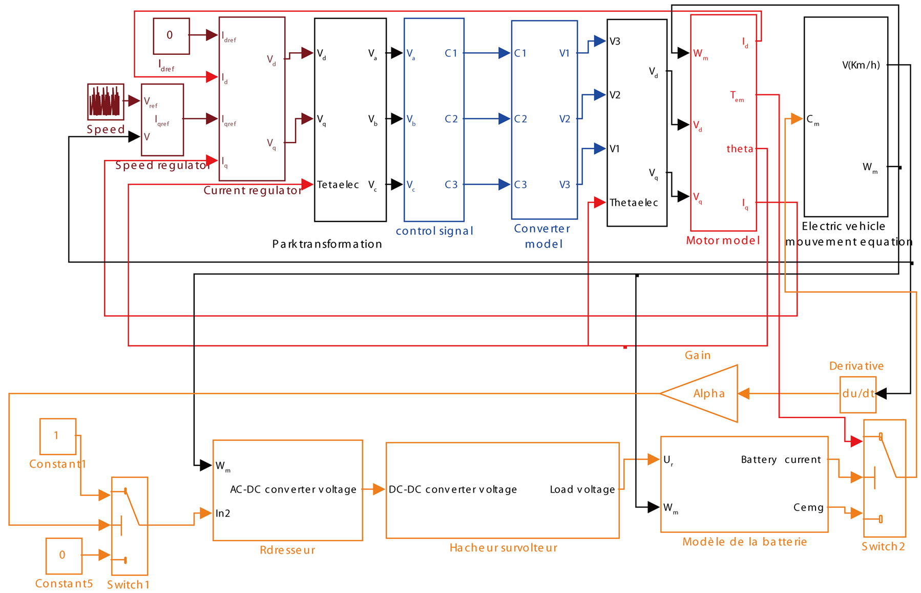
Figure 10. Block diagram of the power chain Simulink model.
The speed response follows the normalized circulation mission with a good precision, what explains the efficiency of the control technique. This characteristic valid entirely the systematic design approach of the power chain retailed in [2].
The load current of batteries (figure 16) is equal to zero during the phase of working in motor and it’s different to zero during the phases of strong decelerations.
The recovered energy (figure 17) increases at the time of strong decelerations and remain constant during the phases of working in motor.
The middle value of the recovered energy is equal to 0.0718 kwh on a length of 1027 seconds. This value is important, what shows the efficiency of the system of energy recuperation. The recovered energy improves the autonomy in relation to another system of traction without recuperation with autonomy of 120 km for a stocked energy equal to 30 kwh [10].
The torque on the motor tree (figure 18) presents negative values since at the time of working in generat-

Figure 11. Speed response to an order of 80 km/h.

Figure 12. Evolution of the phase current according to the time for a speed order of 80 km/h.

Figure 13. Pace of the electromagnetic torque for a working regime with constant speed of 80 km/h.
ing the motor torque reverses itself.
10. Conclusions
In this paper, we present a validation methodology of the

Figure 14. Pace of the current and the phase voltage for a regime of working to constant speed of 80 km/h.

Figure 15. Response to a normalized circulation mission.

Figure 16. Battery load current.
systematic design approach of electric vehicle power train retailed in [3]. This approach also treats the problem

Figure 17. Recovered energy.

Figure 18. Torque on the motor tree.
of improvement of the autonomy. Indeed, a vector control strategy integrating a system of energy recuperation optimized is developed and implanted under the environment of Matlab/Simulink. After the manufacture of the motor and the converter, it will be interesting to integrate this control law of the power chain on a DSP or FPGA to test the validity of the global design approach of this power chain reducing the consumption. Finally, the gotten results are encouraging and open the track to the industrialization of this traction system.
REFERENCES
- S. A. Randi, S. Astier and B. Sarenti, “Full Modeling Approach of Electric Vehicle for Design Optimisation,” Electric Vehicle Symposium (EVS 18), Berlin, 20-24 October 2001.
- S. Tounsi and R. Neji, “Design of an Axial Flux Brushless DC Motor with Concentrated Winding for Electric Vehicles,” Journal of Electrical Engineering, Vol. 10, 2010, pp. 134-146.
- N. Chaker, I. B. Salah, S. Tounsi and R. Neji, “Design of Axial-Flux Motor for Traction Application,” Journal of Electromagnetic Analysis and Applications, Vol. 1, No. 2, 2009, pp. 73-83. doi:10.4236/jemaa.2009.12012
- R. Neji, S. Tounsi and F. Sellami, “Contribution to the Definition of a Permanent Magnet Motor with Reduced Production Cost for the Electrical Vehicle Propulsion,” European Transactions on Electrical Power, Vol. 16, No. 4, 2006, pp. 437-460. doi:10.1002/etep.95
- B. B. Salah, A. Moalla, S. Tounsi, R. Neji and F. Sellami, “Analytic Design of a Permanent Magnet Synchronous Motor Dedicated to EV Traction with a Wide Range of Speed Operation,” International Review of Electrical Engineering, Vol. 3, No. 1, 2008, pp. 110-122.
- A. Moalla, S. Tounsi and R. Neji, “Determination of Axial Flux Motor Electric Parameters by the Analytic-Finite Elements Method,” Journal of Electrical Systems, Vol. 4, No. 4, 2008, pp. 398-409.
- A. Ammous, B. Allard and H. Morel, “Transient Temperature Measurements and Modeling of IGBT’s under Short Circuit,” IEEE Transaction Electronic Devices, Vol. 13, No. 1, 1998, pp. 12-25.
- M. Ayadi, A. Ammous, Y. Ounejjar and F. Sellami: “Thermal Interaction of Semiconductor Devices in Multi-Chip Modules,” Systems Man and Cybernetics SMC’02, Hammamet, October 2002.
- S. Tounsi, M. H. Kacem and R. Neji, “Design of Static Converter for Electric Traction,” International Review on Modelling and Similations, Vol. 3, No. 6, 2010, pp. 1189- 1195.
- S. Tounsi, R. Neji, N. B. Hadj and F. Sellami: “Global Optimization of Electric Vehicle Design parameters,” Electric Vehicle Symposium (EVS21), Monaco, 2-6 April 2005.
Nomenclature

