Journal of Electromagnetic Analysis and Applications
Vol. 3 No. 7 (2011) , Article ID: 5910 , 4 pages DOI:10.4236/jemaa.2011.37046
Frequency Range Dependent TE10 to TE40 Metallic Waveguide Mode Converter
![]()
Graduate School of Engineering, University of Hyogo, Himeji-shi, Hyogo, Japan.
Email: kokubo@eng.u-hyogo.ac.jp
Received April 26th, 2011; revised May 25th, 2011; accepted June 7th, 2011.
Keywords: Metallic waveguide, Dielectric rod, Mode converter
ABSTRACT
Dielectric rod arrays in a metallic waveguide alter the propagation modes and group velocities of electromagnetic waves. We focus on TE10-to-TE20 mode converters and investigate the variation in their behavior with frequency. In this investigation, a mode converter is proposed that passes the TE10 mode at frequencies lower than 2fc, and converts the TE10 mode into the TE40 mode for frequencies higher than 2fc, which is achieved by a combination of TE10-TE20 mode converters.
1. Introduction
Metallic waveguides have major advantages, such as low propagation loss and high power transmission in the microwave frequency range. However, one disadvantage is that the usable frequency range is restricted to fc < f < 2fc, because the TE20 mode is possible in the frequency region higher than 2fc for rectangular metallic waveguides. A ridge waveguide [1] (or double-ridge waveguide) has an advantage in that it can spread the propagating frequency range as a result of reduction in the cutoff frequency for the TE10 mode. However, one disadvantage is that the construction of the waveguide structure is complex.
Power sources, such as watt-class impact ionization avalanche transit-time (IMPATT) diodes or Gunn diodes, are readily available and for high frequency use, these power sources are sometimes combined due to their low power rating. Power dividers and power combiners may be easily set up using mode converters. For example, a TE10-TE30 mode converter easily offers a three-port power divider, and a three-way power combiner can be arranged by reversal. A power combiner is useful for application to Gunn diodes in a waveguide array [2], because it converts the TE30 mode to the TE10 mode.
2. Frequency Range Dependent TE10 to TE20 Mode Converter
We have reported a mode converter that passes the TE10 mode at low frequencies and converts the TE10 mode into the TE20 mode at high frequencies [3]. The reflection of the TE20 mode, however, is not small enough because an asymmetrical arrangement increases the reflection of the TE20 mode. In this investigation, a new mode converter is proposed that passes the TE10 mode at low frequencies and efficiently converts the TE10 mode into the TE40 mode at high frequencies. The structure contains the proposed TE10-TE20 mode converters.
Figure 1 shows the frequency eigenvalues of a conventional metallic waveguide for a given k wave vector. In this figure, the wave vector k and frequency ω are normalized by the waveguide width w. The waveguide allows propagation of only the TE10 mode for 0.5 < ωw/2πc < 1, and only the TE10 and TE20 modes for 1 < ωw/2πc < 1.5. If the TE10 mode is converted into the TE20 mode, the group velocity A of TE10 must change to the group velocity B of TE20 for 1 < ωw/2πc. However, the group velocity C is not changed for 0.5 < ωw/2πc < 1, because it remains in the TE10 mode.
A metallic waveguide that contains in-line dielectric rods can allow propagation of single modes in two frequency regions [4]. For example, Figure 2 shows the eigenvalues of a waveguide in which dielectric rods are periodically positioned along the central axis of the waveguide. The dielectric constant of the rods is assumed to be εr = 24 and their radius is r = 0.064a (where a represents the spatial period of the dielectric array). The propagation modes in a waveguide with in-line dielectric
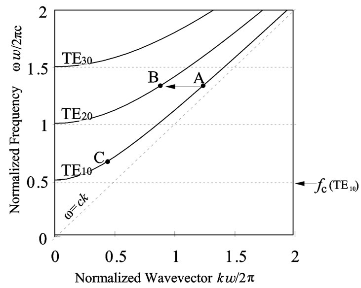
Figure 1. Frequency eigenvalues of a conventional metallic waveguide for a given wave vector k.
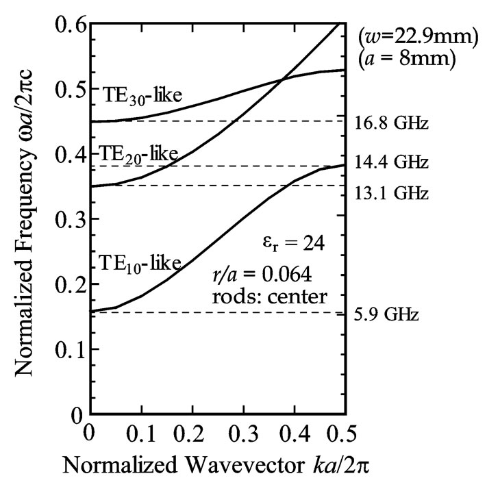
Figure 2. Frequency eigenvalues of a waveguide in which dielectric rods are placed periodically along the central axis. The dielectric constant of a rod is assumed to be εr = 24 and the radius is assumed to be r = 0.064a.
rods of period a are calculated using a supercell approach [5] by applying appropriate periodic Bloch conditions at the boundary of the unit cell [6,7]. In Figure 2, if a = 8 mm and w = 22.9 mm (WR-90 waveguide), then the electromagnetic wave propagates in a single mode for 5.9 - 13.1 GHz (TE10-like mode) and 14.4 - 16.8 GHz (TE20- like mode).
If the transverse electromagnetic field distribution is gradually changed from TE10 to TE20 and the group velocity A is gradually changed to B, then reflection may be reduced for 1 < ωw/2πc. However, if the group velocity C is not significantly changed, reflection may be suppressed for 0.5 < ωw/2πc < 1. The mode profile gradually shifts from TE10 to TE20; therefore, the position of the dielectric rods is changed from near the sidewall of the waveguide to the center, as shown in Figure 3. The
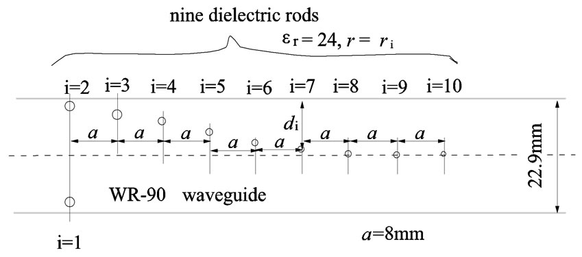
Figure 3. Proposed structure of the TE10-to-TE20 mode converter.
first rod (i = 1) is located at the opposite side of the second rod (i = 2), because a symmetrical arrangement will decrease the reflection of the TE20 mode.
The group velocity is given by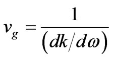 ; however, the group velocity for the waveguide depicted in Figure 3 cannot be determined easily. When the position of the dielectric rods is fixed to d, the group velocity vg in the first band is changed by variation of the radius r. However, the group velocity in the second band is simultaneously changed; thus, the two group velocities cannot be changed independently.
If the group velocity is normalized using the velocity of light in a vacuum c0, then vg/c0 will be the same as the gradient of the characteristic curve. Therefore, when d and r are fixed to specific values, vg/c0 can be calculated for the periodic structure of dielectric rods at a specific frequency. If group velocity A is gradually changed to B for 1 < ωw/2πc while d is varied and group velocity C is not changed for 0.5 < ωw/2πc < 1, then one unit of each pair of d and r connects to its respective pair to form the structure shown in Figure 3.
The metallic waveguide width is assumed to be w = 22.9 mm, (WR-90; fc ≈ 6.55 GHz), and the period a is fixed at 8 mm. Figure 4 shows a sample of the calculated normalized velocity along the waveguide axis at 8 and 16 GHz for dielectric rods (LaAlO3: εr = 24; radius r [mm]) aligned at a distance d [mm] from the sidewall. It is desirable that the normalized velocity A (TE10: vg/c0 = 0.912) decreases monotonically to B (TE20: vg/c0 = 0.574) at 16 GHz and the normalized velocity C (TE10: vg/c0 = 0.574) is not changed at 8 GHz. However, at 16 GHz, this condition is not satisfied near d = 10 mm, because a dielectric rod is located at the point where the electric field is a minimum. On the other hand, if the dielectric rod is placed near the sidewall of the waveguide, it will be located at the point where the electric field is a maximum. The characteristics are complex in the transition region (near d = 10 mm). The waveguide must be designed so as not to vary the group velocity at 8 GHz. After calculating vg for pairs of di and ri, if group velocity A
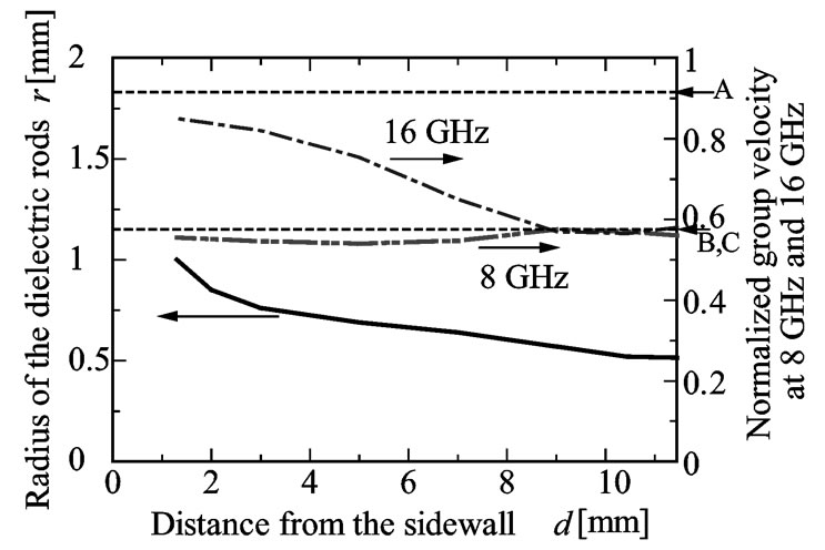
Figure 4. Group velocity (dotted lines) in a metallic waveguide containing a periodic array of dielectric rods for various distances d, location of the rods, and corresponding radii ri (solid line) of the rods, at 8 and 16 GHz.
 (a)
(a)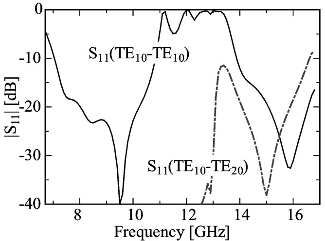 (b)
(b)
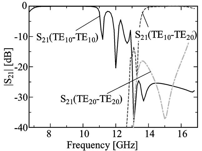
Figure 5. S parameters for the TE10-to-TE20 mode converter. (a) |S21|, and (b) |S11|.
is gradually changed to B, then each pair of di and ri are combined (see Figure 3).
The last rod (i = 10) has r1 = 0.36 mm and the remainder have a cross-sectional radius of 0.515 mm to reduce electromagnetic reflection at low frequencies. Ten dielectric rods are placed from near the sidewall to the center with decreasing rod radius ri and with constant a (=8 mm). Table 1 shows the relation between the distance di and radius ri. The S parameters between the input port
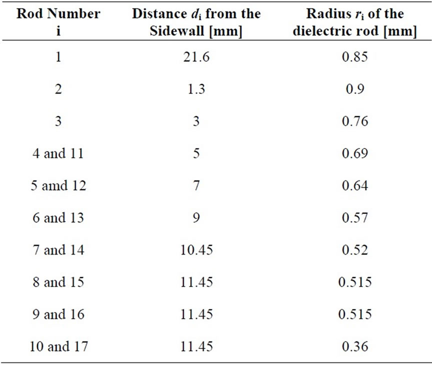
Table 1. Location and radius of the dielectric rods.
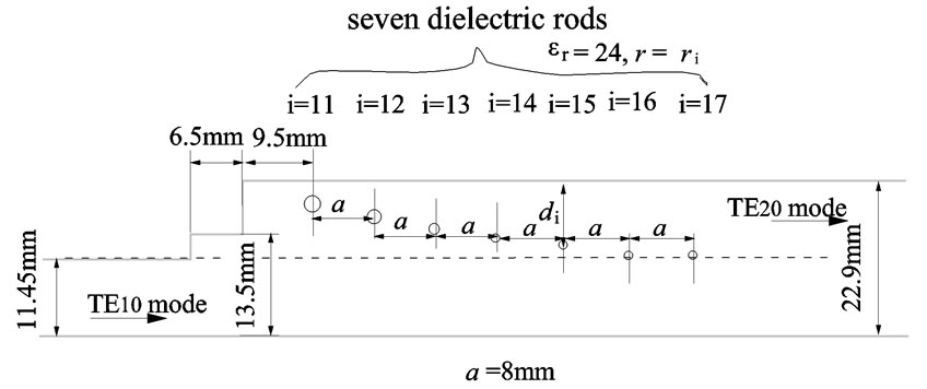
Figure 6. Structure of the proposed TE10-to-TE20 mode converter.
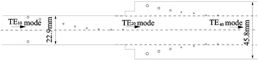
Figure 7. Structure of the proposed TE10-to-TE40 mode converter.
(port 1) and output port (port 2) were calculated using HFSS software by Ansoft [8], and the results are shown in Figures 5(a) and (b). Electromagnetic waves propagate as the TE10 mode for 7.2 - 10.7 GHz and the TE10 mode is converted into the TE20 mode for 14.2 - 16.4 GHz at an efficiency of over 95%.
3. Frequency Range Dependent TE10 to TE40 Mode Converter
A TE10 to TE40 mode converter can be considered by combination of TE10 to TE20 mode converters. Another structure of the TE10-to-TE20 mode converter is proposed and is shown in Figure 6. The locations of the dielectric rods are indicated in Table 1. The structure of the proposed TE10-to-TE40 mode converter, which is composed of three TE10-to-TE20 mode converters, is shown in Fig-
 (a)
(a)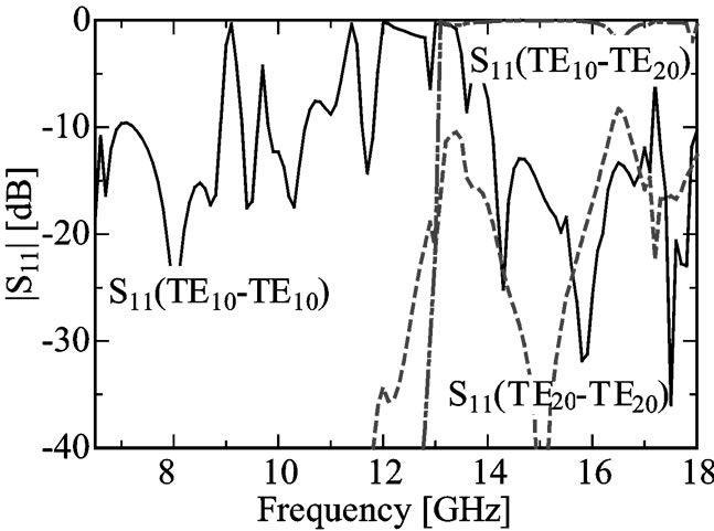 (b)
(b)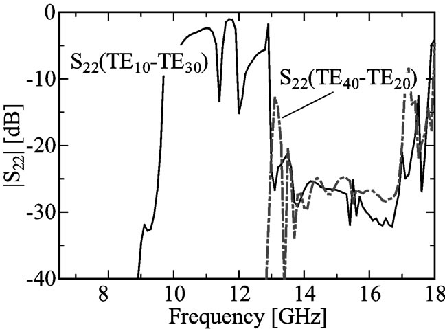 (c)
(c)
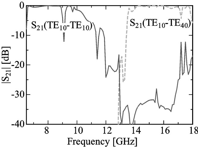
Figure 8. S parameters for the TE10-to-TE40 mode converter. (a) |S21|, (b) |S11|, and (c) |S22|.
ure 7. The S parameters between the input port (port 1) and output port (port 2) calculated using HFSS are shown in Figures 8(a)-(c).
4. Conclusions
We have previously reported that single-mode propagation is possible in a metallic waveguide with dielectric rod arrays along its central axis using the TE10 and TE20 modes. A new mode converter is proposed that propagates the TE10 mode at low frequencies and converts the TE10 mode into the TE40 mode at high frequencies by slight variation of the group velocity. It was shown that electromagnetic waves propagate as the TE10 mode around 8 GHz and that the TE40 mode is converted into the TE10 mode around 16 GHz.
5. Acknowledgements
This work was supported by KAKENHI (22560336).
REFERENCES
- S. B. Cohn, “Properties of Ridge Wave Guide,” Proceedings of the IRE, Vol. 35, No. 8, 1947, pp. 783-788. doi:10.1109/JRPROC.1947.226277
- J. Bae, T. Unou, T. Fujii and K. Mizuno, “Spatial Power Combining of Gunn Diodes Using an Overmoded-WaveGuide Resonator at Millimeter Wavelengths,” IEEE Transactions on Microwave Theory and Techniques, Vol. MTT- 46, No. 12, 1998, pp. 2289-2294.
- Y. Kokubo, “Frequency Range Dependent TE10 to TE20 Mode Converter,” Microwave and Optical Technology Letters, Vol. 52, No. 1, 2010, pp. 169-171. doi:10.1002/mop.24886
- Y. Kokubo, “Wide Band Metallic Waveguide with in-Line Dielectric Rods,” IEEE Microwave Theory and Wireless Component Letters, Vol. 18, No. 2, 2008, pp. 79-81. doi:10.1109/LMWC.2007.915028
- H. Benisty, “Modal Analysis of Optical Guides with Two-Dimensional Photonic Band-Gap Boundaries,” Journal of Applied Physics, Vol. 79, No. 10, 1996, pp. 7483- 7492. doi:10.1063/1.362419
- M. Boroditsky, R. Coccioli and E. Yablonovitch, “Analysis of Photonic Crystals for Light Emitting Diodes Using the Finite Difference Time Domain Technique,” Proceedings of SPIE, Vol. 3283, No. 310, 1998, pp. 184-190. doi:10.1117/12.316682
- Y. Kokubo and T. Kawai, “Wide Band Metallic Waveguide with Asymmetric in-Line Dielectric Rods,” IEICE Transactions on Electronics, Vol. E91-C, No. 12, 2008, pp. 1966-1968. doi: 10.1093/ietele/e91-c.12.1966
- Ansoft-Corporation, “Introduction to the Ansoft Macro Language,” HFSS V10, 2005.