Journal of Electromagnetic Analysis and Applications
Vol. 2 No. 7 (2010) , Article ID: 2339 , 8 pages DOI:10.4236/jemaa.2010.27057
H0i-Eigenwave Characteristics of a Periodic Iris-Loaded Circular Waveguide
![]()
Theoretical Radiophysics Department, V. N. Karazin Kharkov National University, Kharkov, Ukraine.
Email: {Katenev, heshi}@univer.kharkov.ua
Received May 26th, 2010; revised June 14th, 2010; accepted June 18th, 2010.
Keywords: periodic structure, pass/stop band, periodicity dispersion, partial waves
ABSTRACT
H0i-eigenwave characteristics of a periodic iris-loaded circular waveguide (PICW) are examined, as concerns the eigenmode behavior vs arbitrary variations of the geometric parameters and the Bragg bandwidths vs the parameter of filling  extremums.
1. Introduction
The periodic iris-loaded circular waveguide, Figure 1, has long since found its several important applications, e.g. in the particle acceleration field [1], and thus stimulated its electromagnetics studies. Despite this even its eigenwave characteristics available are not to be regarded as generally satisfactory [1,2]; foremost theoretically and a good deal so [2], whereas exactly knowing the ropes wouldn’t do any harm in all respects.
Certain conceptual points as to the eigenwave propagation in PICW are given in [2] to get those waves theory building started. As the next step and immediate continuation, this paper is concerned with characterization of one of the PICW particular wave types - its H0i-eigenwaves.
It is not that only the PICW asymmetric and symmetric E0i-waves, in view of their acknowledged complexity [1,3], cannot be properly perceived except by rigorous computations. Any simplified modeling, e.g. as that of l ® 0, d ® 0 in [3], and others like it, are
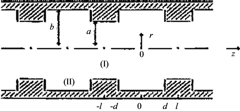
Figure 1. Periodic iris-loaded circular waveguide
rather unsatisfactory, concerning even the simplest guided wave type of H0i-waves. And in fact, there is no other way at all for dealing adequately with the PICW eigenwave problem except via rigorous computations; which is certainly one of the major difficulties in their investigation.
This way, the H0i-waves are generally looked at on the dispersion side of their electromagnetics; and all of the necessary terms, notions and ways employed are introduced and discussed in detail in [2].
2. Arbitrary Geometric Parameters
As some work model of PICW to be employed throughout this investigation [2], and in this section in particular, radius b is held constant b º 3, the long period l = 3 and the short one l = 0.75 are examined in detail, as one of the wide and one of the narrow cells are considered, and radius a is optimally varied.
The multi-mode Brillouin diagrams is the most suitable instrument for the purpose.
The PICW dispersion curves are drawn below with solid lines, those of the regular waveguide b = 3 with dotted lines, and those of the regular waveguide r = a with dashed ones.
2.1 Period l = 3
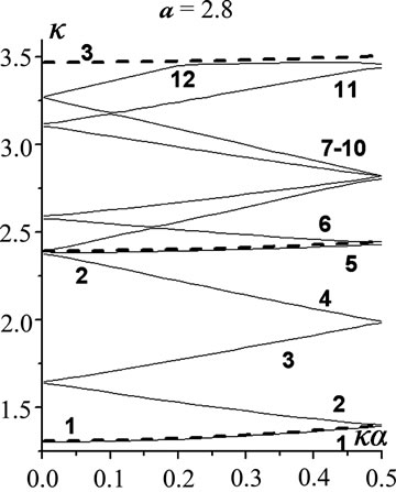
At the narrow iris for d = 2.8, the effect of radius a variations is represented in Figure 2 for the junior 12 modes and a Î {2.8, 2.4, 2, 1.2, 0.4}.
The initial periodicity dispersion (i.p.d.) is quite in effect at a = 2.8, and H01, H04 are the regular PICW modes originated in accordance with the regular waveguide r = 3 modes , respectively. All the other eigenmodes are the periodicity ones generated by the former: H02, H03 and H011, H012 by H01 (
 ), H05, H06 and H09, H010 by H04 (
 ). The modes H011, H012 are the most complex ones due to the effect of
  mode involved. Down to a = 2, all the senior modes of those presented are clearly piecewise composed. Ultimately, at a = 0.4, the closedoff H05, H06 and H011, H012 get in very close vicinities in between.
There are three regular waveguide r = b modes , i = 1,2,3, in the bandwidth. And as radius a decreases, a monotonous growth of all of the eigenfrequences for
  i = 1,…,12, occurs, except in the regular frequencies: {
 }|ka=0.5 for 3 > a > 1.2, {
 }|ka=0.5 for
 .
.
In the waveguide with a fairly thick iris, e.g. d = 0.3, the effect of radius a variations is represented in Figure 3, the junior 12 modes, aÎ{2.8, 2.4, 2, 1.2, 0.8, 0.4}.
Here, the regular waveguide r = a i.p.d. effect is valid up to a = 2 for all of the modes, except in a few of the Bragg bands. At a = 2.8, k = 0, the modes H01, H05 are the regular ones (by , respectively), the mode H05 being only a slightly composed one (the fragment f-1, Figure 4); H02, H03; H04, H06; H011, H012 and H07, H08; H09, H010 are the periodicity modes by
  and
and  respectively. The fragments f-1,2,3, Figure 4, demonstrate, in particular, a significant localization of the periodicity partial-wave effect closely around the Bragg wave-points; as well as some other exact details of the mode forming. For example, in f-2,
  , the modes H07, H010 are formed after
 , the modes H08, H09 after
 , and the corresponding Bragg bands are one inside the other. In f-3,
 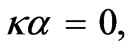 H07, H08 are formed after
  and H09, H010 after
 , and the two Bragg bands go one by one.
A certain regular-waveguide r = a modeling may be in some validity in this case, whereupon the eigenfrequency equals the regular model’s one for the upper boundaries  of the appropriate Bragg bandwidths
  so that
 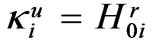 |ka = 0.5.
2.2 Period l = 0.75
At the wide cell d = 0.65, radius a variations are demonstrated in Figure 5, 12 modes, a Î {2.8, 2.4, 2, 1.2, 0.4}.
 (a)
(a) (b)
(b) (c)
(c) (d)
(d) (e)
(e)
Figure 2. l = 3, d = 2.8; the effect of radius a variations (a) a = 2.8; (b) a = 2.4; (c) a = 2; (d) a = 1.2; (e) a = 0.4
 (a)
(a)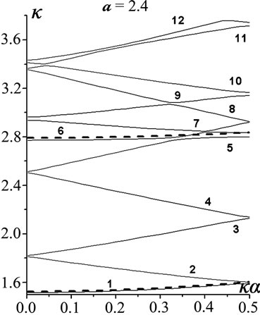 (b)
(b)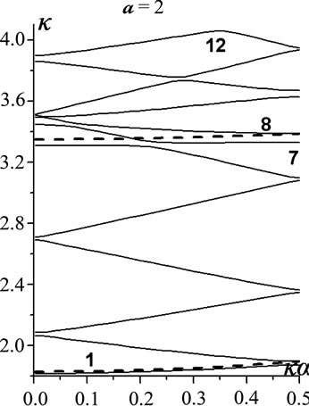 (c)
(c)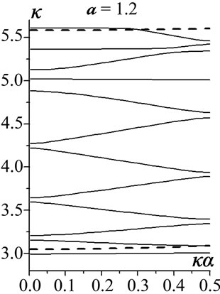 (d)
(d) (e)
(e)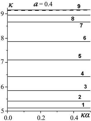 (f)
(f)
Figure 3. l = 3, d = 0.3; radius a variations (a) a = 2.8; (b) a = 2.4; (c) a = 2; (d) a = 1.2; (e) a = 0.8; (f) a = 0.4
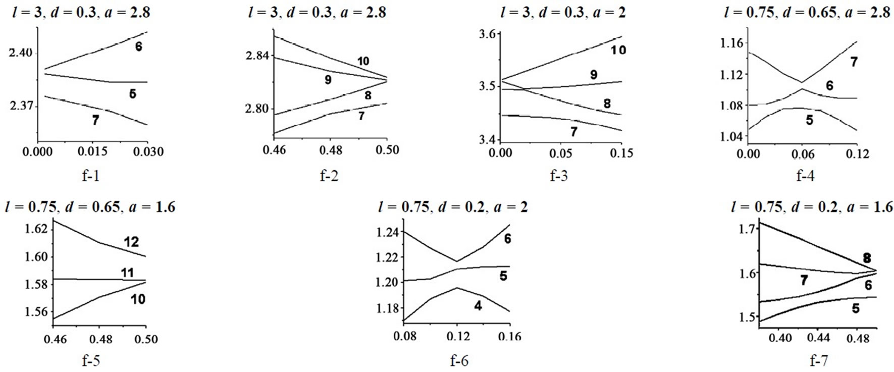
Figure 4. Some particularities of the eigenmode formation as radius a varies
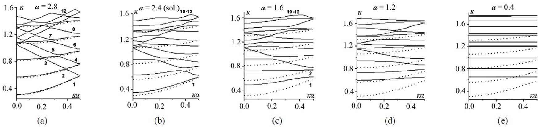
Figure 5. l = 0.75, d = 0.65; radius a variations (a) a = 2.8; (b) a = 2.4; (c) a = 1.6; (d) a = 1.2; (e) a = 0.4
At a = 2.8, the modes H0i, i = 1,2,3,6,11, are the regular ones in one-to-one correspondence with , i = 1,2,3,4,5, consequently. Of the rest modes, H04, H05 (by
 ), H07, H08 (by
 ), H09, H010 (by
 ) and H012 (by
 ) are the periodicity ones. Eventually, at a=0.4, the closed-off H04, H05 and H07, H08 and H011, H012 are very close in between.
The piece-wise mode composition due to a lot of the inner Bragg wave-points and the wave propagation up to rather small radius a values, characterize the waves. Two particular cases as to the mode forming are shown in detail in the fragments f-4 and f-5, Figure 4.
The regular-waveguide r = b modeling scheme is not relevant in this case, even to the extent it has been in {l = 3, d = 2.8} event; much less is the r = a scheme.
At the thick iris d = 0.2, the effect of radius a variations is demonstrated in Figure 6 for the junior 12 modes, a Î {2.8, 2.4, 2, 1.2, 0.4}; with two detailed fragments on the particularities of the mode forming, f-6 and f-7, Figure 4.
As radius a goes down, the i.p.d. is still mainly in effect up to a = 1.2; which is evidenced by a fairly straight geometry of the dispersion curves.
The regular-waveguide r = a modeling scheme as that in the previous thick-iris event, Figure 3, principally holds true in this case also , and even more accurately.
The fragments f-1 to f-7, Figure 4, exhibit some particular features of the eigenmode formation and transformation in the waveguide. As the values of d and a parameters vary, the standard i.p.d. scheme of the periodicity mode origin in pairs at , and their further forming at 0 <
  < 0.5, somewhat changes to include at least three interacting eigenmodes. As it is in f-1, H05 being the regular mode (
 = 0); in f-4, H06 the regular mode, in f-6, H05 the regular mode (0 <
  < 0.5); in f-7, H07 the regular mode (
 = 0.5). In f-2, f-3, (
 = 0.5), mentioned above, all of the modes involved are the periodicity ones which, at least after the dispersion way of analysis, quite conform to the standard i.p.d. scheme [2].
3. The Bragg Bandwidths Extremums
Another view on the H0i-eigenwave behavior is via their Bragg bandwidths  extremum characteristics vs the parameter of filling 0 < q = d/l < 1 [4]. In essence, this is the d-parameter variation in the waveguide in effect, looked at under a quite promising aspect as to the PICW characterization. For one thing, such graphic representation of those bandwidths behavior as that, e.g., in Figure 7, enables to look simultaneously at both stop and pass bandwidths characteristics. And second, the other PICW eigenwave types do display a good deal of analogical behavior, with certain peculiarities of their own [4].
In this section, the period values considered are l = 5, 3, 1.8, 1, 0.75. According to the classifications in [2], l = 5, 3, 1.8 are the long periods, l = 1, 0.75 are the short ones; and thus, some borderline set of the period values is examined below.
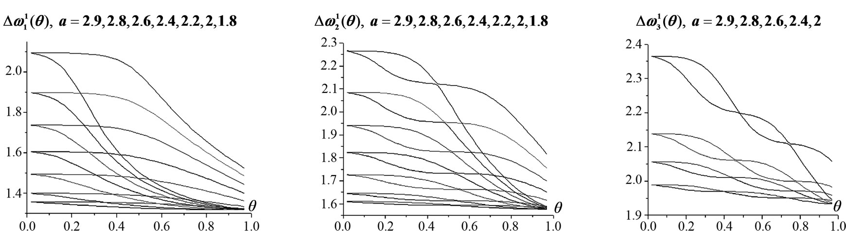
The general rule for the periodicity modes originated by a given regular one in PICW (after the i.p.d.) is that ,
,  = 0, 0.5, have i maxima and i-1 minima over the interval 0 < q < 1; while
  ® 0 as q ® 0
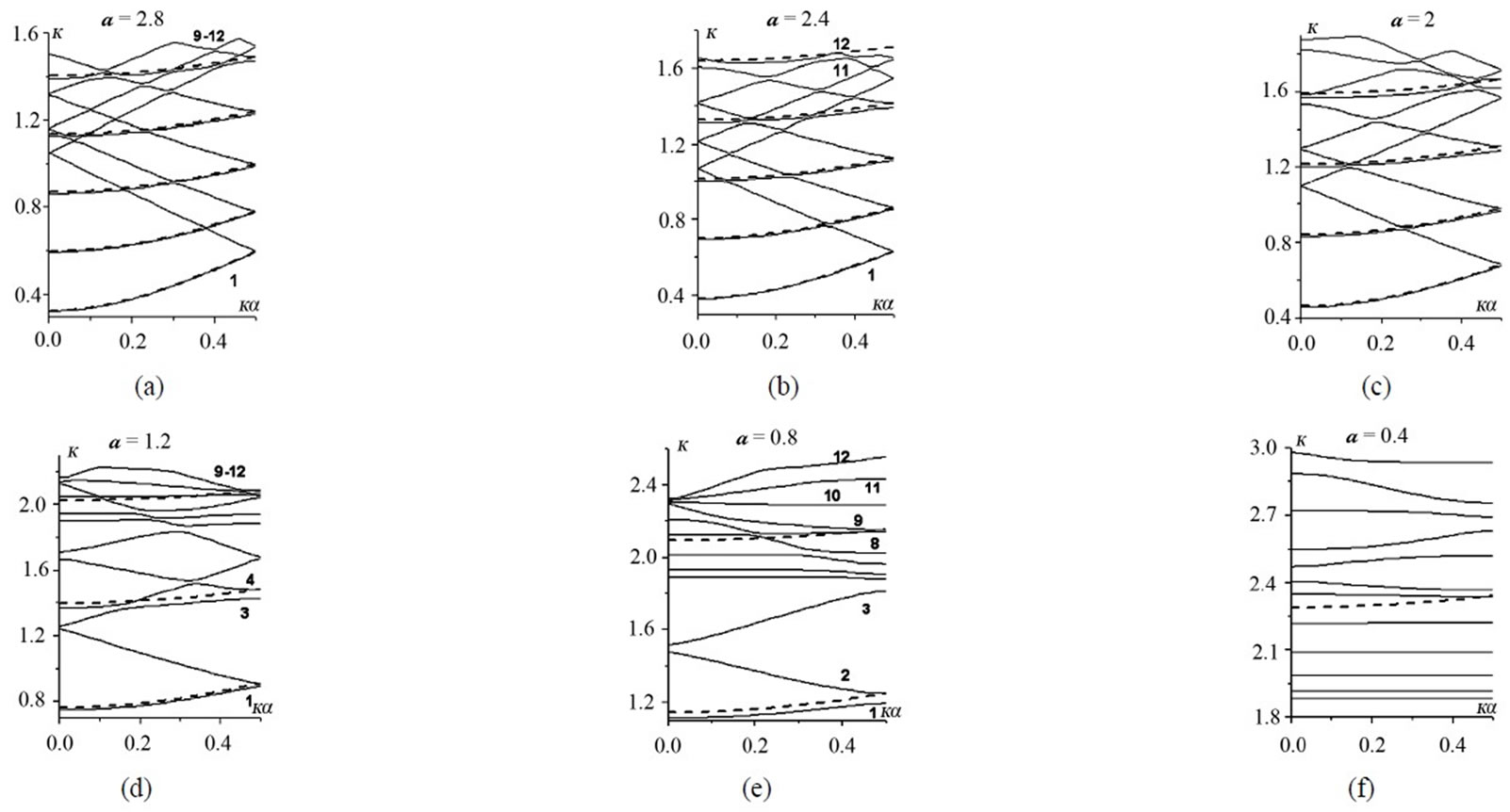
Figure 6. l = 0.75, d = 0.2; radius a variations (a) a = 2.8; (b) a = 2.4; (c) a = 2; (d) a = 1.2; (e) a = 0.8; (f) a = 0.4
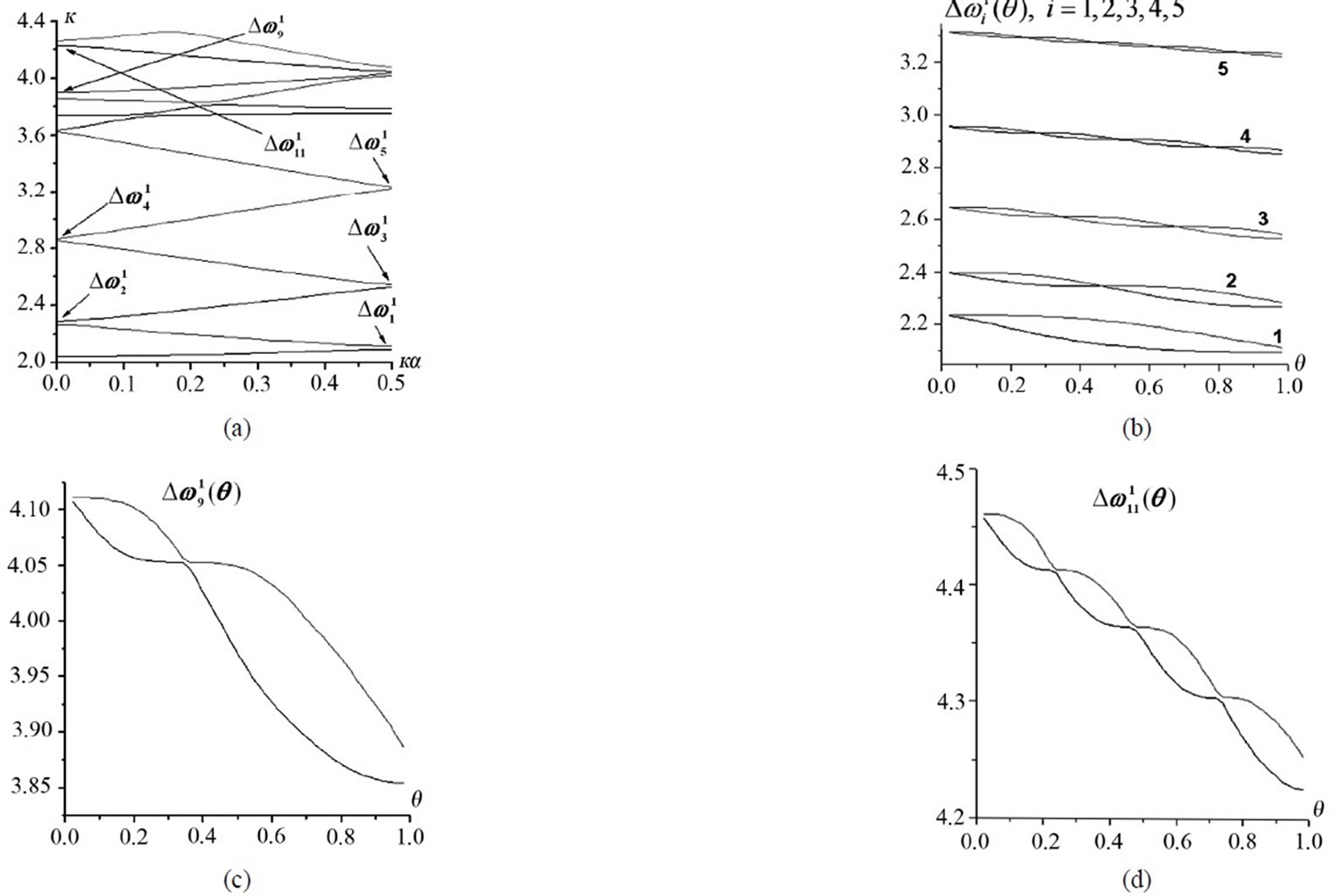
Figure 7. l = 5, a = 2.8; the Bragg bandwidths 
(infinitesimally thin slot) and  ® w > 0 as q ® 1 (infinitesimally thin iris).
In Figure 7, l = 5, d = 4.8, a = 2.8, there are the Brillouin diagram for 12 junior modes, Figure 7 (a), and seven of its Bragg bandwidths , i = 1,2,3,4,5,9, 11, represented via their upper and lower boundaries
  and
and  vs
vs ,
,  , Figures 7 (b), (c) and (d). The bandwidths
  and
and  are of a similar origin by their regular “parent” modes:
  are originated by
 ,
,  by
by . And while the partial-wave interactions for the bandwidths
 , i = 1,2,3,4,5, are originally entirely symmetrical, they are not so for
 , j = 9,11. Because the nonsymmetrical partial-wave interactions in the appropriate inner B. w.-p. (0 <
  < 0.5) do have their effects regarding
  bandwidths, though quite slightly there.
The graphic representation of the PICW pass 
 , and stop
  bandwidths of Figure 7 (b) (and every vertical line
  there, yields us those in PICW) is equivalent to the continuum of the Brillouin diagrams of Figure 7 (a) for
 , d Î [0,1]. In view of the relationship of equivalence between the wave and the dispersion equations [see, e.g. 2], Figure 7 (b) has, in its way, everything on the
  -waves, i = 1,2,…,5, as a function of d.
The effects of radius a variation for l = 3,  , i = 1,2,3, are shown in Figures 8 (a)-(c), accordingly.
The bandwidths , l = 1.8, a = 2.8, are presented in Figures 9 (b) and (c).
 , l = 1, a = 2.9, are presented in Figures 10 (b)-(e), accordingly. The bandwidths
  for the inner B. w.-p.s are much harder to examine, because their eigenvalue
  shifts as q varies. Nevertheless certain extremums of the bandwidths are obviously available in this case also.
And finally, 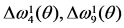 , l = 0.75, a = 2.8, are given in Figures 11 (b) and (c). The presence of the inner Bragg wave-points for all of the eigenmodes on the short [2] periods (wherein l = 1, l = 0.75 are such ones), with their asymmetrical partial-wave interactions, does distort the regularity of the max/min pattern of above; which can be seen in
  case, Figure 11 (b). Yet for
 , Figure 11 (c), these extremums are still clearly available.
4. Conclusions
Under the fundamental primary-causal influence of the
 (a) (b) (c)
Figure 8. l = 3; the Bragg bandwidths , as radius a varies
 (a) (b) (c)
Figure 9. l = 1.8, a = 2.8; the Bragg bandwidths 
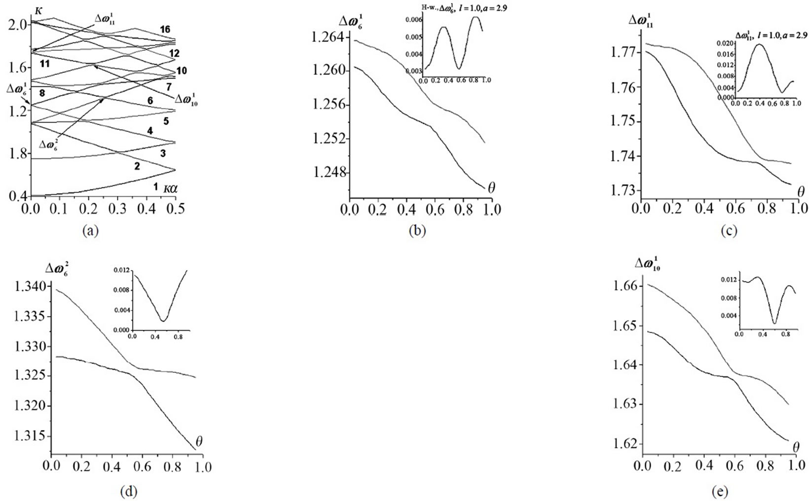
Figure 10. l = 1, a = 2.9; the Bragg bandwidths  and
and 
 (a) (b) (c)
Figure 11. l = 0.75, a = 2.8; the Bragg bandwidths 
period value, in particular, in setting the number of eigenmodes, with all the consequences of the i.p.d. network thus produced [2], and further variations of d and a parameters, the PICW H0i-eigenwave characteristics can be seen are quite complex; even without any of their power-flow treatment, illustrated in [2].
These waves are not to be satisfactorily interpreted by some regular-waveguide modeling schemes, though the latter may be in some validity to this case.
A monotonous response of the H0i-eigenfrequencies to both d and a variations,  , is a major characteristic feature of those waves. Wherein,
  , as
, as  (the i.p.d. of the regular r = a waveguide via the narrow cell),
  , as
, as ,
,  monotonously grows as a decreases from b downwards (the regular r = b waveguide modeling, with the narrow-iris l-d effect in the waveguide). As a result, each H0i, is stable (approximately constant) vs a at its upper iegenfrequency
 , i.e. either at
  or
or . In fact
  monotonously and rather slightly grows as a decreases.
Since the PICW eigenwaves originate principally due to interactions in the Bragg wave-points (e.g., after the partial-wave model [2]), the Bragg bandwidths  extremum law of i/i-1 maxima/minima at
  {0.5, 0}, presented here in brief, can be treated as the general periodicity law of the Bragg bandwidths variation vs q. The limits and specificity of its holding true as radius a varies, are different for different wave types [4].
It needs a special power flows investigation in order to further physically interpret this law in proper detail and understanding.
And finally, the upper-and-lower-boundary representations of the pass and stop bandwidths,  like those in Figure 7(b), are instrumental and informative enough, as regards
  variations, to be in their way some 3rd full-right member of the relationship of equivalence in the matter, see, e.g., [2].
REFERENCES
- O. A. Valdner, N. P. Sobenin, B. V. Zverev and I. S. Schedrin, “A Guide to the Iris-loaded Waveguides,” in Russian, Atomizdat, Moscow, 1977.
- S. K. Katenev, “Eigenwave Characteristics of a Periodic Iris-Loaded Circular Waveguide. The Concepts,” Progress in Electromagnetic Research, Vol. 69, 2007, pp. 177-200.
- Y. Garault, “Etude D’Une Classe D’Ondes Electromagnetique Guidées: Les Onde EH. Application aux Dèflectuers Haute Frèquence de Particules Rapides,” Annales de Physiques, Vol. 10, 1965, pp. 641-672.
- S. K. Katenev and H. Shi, “Stop Bandwidth Extremums of a Periodic Iris-Loaded Circular Waveguide,” 6th International Conference on Antenna Theory and Techniques, Sevastopol, 17-21 September 2007, pp. 471-473.
List of Notations Pertaining to the Problem
1.  ≡
≡ — Bragg wave-number and its ordinate on the Brillouin plane
 , i.e., the Bragg wave-point (B. w.-p.);
2.  — Bragg band, i.e., a (locally) forbidden band;
  — the i-mode propagation band and all of its possible Bragg bands (the mode being beneath those);
3. periodicity dispersion — the first one of the two factors — periodicity and diffraction — responsible for the waveguide dispersion forming;
4. initial periodicity dispersion (i.p.d.) — the waveguide dispersion at infinitesimal irises;
5. regular mode — the PICW eigenmode in one-to-one correspondence to that of the smooth waveguide;
6. periodicity mode — the PICW eigenmode originating due to the periodicity effect;
7. partial waves — the independent ingredients of a PICW eigenwave.