Journal of Electromagnetic Analysis and Applications
Vol. 2 No. 4 (2010) , Article ID: 1680 , 6 pages DOI:10.4236/jemaa.2010.24033
Guided Modes in a Four-Layer Slab Waveguide with Dispersive Left-Handed Material
![]()
1Centre for Optical and Electromagnetic Research, Zhejiang University, Hangzhou, China; 2Science College, Huzhou Teachers College, Huzhou, China; 3Key Laboratory of Specialty Fiber Optics and Optical Access Networks, Shanghai University, Shanghai, China.
Email: shenlufa0410@sina.com
Received December 15th, 2009; revised January 23rd, 2010; accepted February 4th, 2010.
Keywords: Slab Waveguide, Left-Handed Material, Dispersive Properties, Total Power Fluxes
ABSTRACT
A four-layer slab waveguide including left-handed material is investigated numerically in this paper. Considering left-handed material dispersion, we find eight TE guided modes as frequency from 4 GHz to 6 GHz. The fundamental mode can exist, and its dispersion curves are insensitive to the waveguide thickness. Besides, the total power fluxes of TE guided modes are analyzed and corresponding new properties are found, such as: positive and negative total power fluxes coexist; at maximum value of frequency, we find zero total power flux, etc. Our results may be of benefit to the optical waveguide technology.
1. Introduction
Since Smith et al. [1] made firstly the left-handed material (LHM) with negative permittivity and negative permeability in microwaves, it has attracted much attention due to their novel electromagnetic properties. Now, negative refraction has been successfully realized in THz waves, and optical waves [2,3]. Many scholars [4-6] have analyzed symmetric slab waveguide containing LHM. Typical properties of these waveguides including the absence of the fundamental mode, backward propagating waves with negative power flux have been found. The LHM asymmetric slab waveguides and the slab waveguides with LHM cover or substrate have also been investigated [7-9]. Besides, the five-layer slab waveguides with LHM have been investigated and several new dispersion properties have been discovered [10-12]. J. Zhang etc. [13] have studied a four-layer slab waveguide with LHM core by using a graphical method. We know that the graphical method can only determine whether or not the mode exists. Furthermore, most above researches are neglecting LHM dispersion. This is not the practical case.
In this paper, the four-layer slab waveguide with LHM in one layer and right-handed materials (RHMs) in the other layers is investigated. The material dispersion of LHM has been considered. Through Maxwell’s equations, by using a transfer matrix method, two dispersion equations for the TE guided modes are obtained. Solving these equations, we plot some dispersion curves. Compared these curves, some dispersion properties of TE guided modes are obtained. Besides, power fluxes of TE guided modes are calculated in the waveguide and the corresponding curves are plotted, respectively. From these curves we find some new power flux properties.
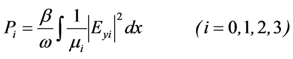
2. Dispersion Equations and Total Power Flux
2.1 Dispersion Equations
A four-layer slab waveguide including LHM is shown in Figure 1. Medium 1 is the LHM, i.e. its dielectric permittivity ( ), magnetic permeability (
 ) and refractive index (
 ) are all negative. However, the cover (medium 0) and the substrates (media 2 and 3) are different conventional materials, thus, their dielectric permittivity (
 ,
, and
and ), magnetic permeability (
 ,
, and
and ) and refractive index (
 ,
, and
and ) are all positive. The thicknesses of media 1, 2 is
  and
and , respectively. Besides, we assume that media 0 and 3 extend to infinity. For simplicity, the time-and z-factor
  that multiplies all the field components is neglected from all equations. Where
  and
and  denote angular frequency and longitudinal propagation constant. Usually, a slab waveguide can support TE and TM modes. In this paper,
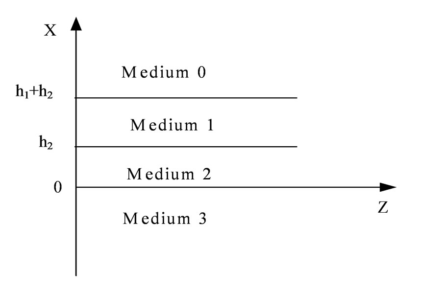
Figure 1. The geometry for a four-layer slab waveguide including left-handed material
we study TE guided modes. For TM modes, they will be investigated in other papers. By using Maxwell’s equations, the only electric field  for TE modes satisfies the following equation:
 (1)
(1)
where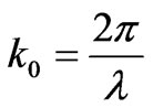 ,
,  is the wavelength in vacuum,
  denotes refractive indexes in media i with
  = 0, 1, 2 and 3, respectively. For different
 , there exist two cases as follows:
Case 1 
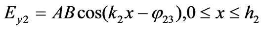
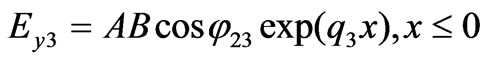
In this case, guided mode fields decay in media 0 and 3, and oscillate in media 1 and 2. We call these modes as the first guided modes and note them . From Equation (1), their electric fields in the slab waveguide are as follows:
 (2)
(2)
 (3)
(3)
 (4)
(4)
 (5)
(5)
where A is an undetermined constant, and
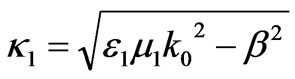 ,
, 
 ,
,  ,
, .
.
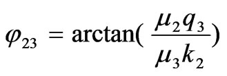
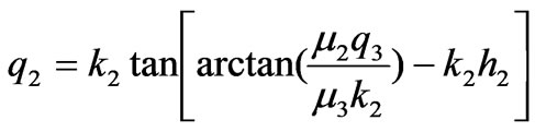
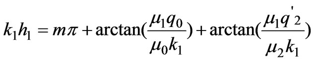
With continuous conditions of the transverse electromagnetic fields and by using the transfer matrix method, a dispersion equation for  mode is obtained as follows:
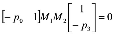 (6)
(6)
where 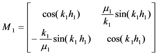 ,
,

After some algebraic manipulation, Equation (6) can be rewritten as:
 (7)
(7)
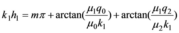
where m = 0, 1, 2, 3, … ,
Case 2 
Under this condition, mode fields are oscillating in medium 1 while decay in the other media. We define these modes as the second guided modes and note them . Let
. Let 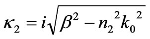 =
= , the transfer matrix
  is rewritten as:
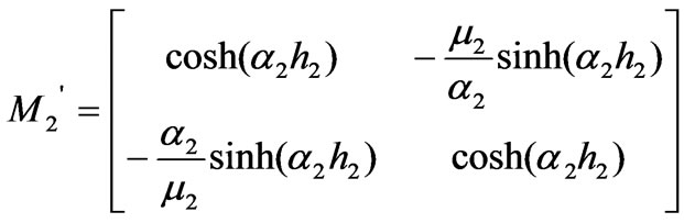
Substituting  into Equation (6), we obtain a dispersion equation for
  modes
modes
 (8)
(8)
where , and m = 0, 1, 2, 3, …
Although the forms of two dispersion Equations (7) and (8) are similar, they have different physical properties. For TM modes, their dispersive equations are similar with that of the corresponding TE modes. But, their magnetic permeability in the equations is replaced by dielectric permittivity.
2.2 The Total Power Flux (TPF)
Power fluxes inside the slab waveguide are calculated by an integral of Poynting vector. For TE guided modes, their power flux ( ) in each layer can be obtained through a following equation.
 (9)
(9)
Substituting Equations (2)-(5) into Equation (9), after some algebraic manipulation, we have the power fluxes inside the waveguide as follows:
 (10)
(10)
 (11)
(11)
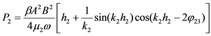 (12)
(12)
 (13)
(13)
where  denote power fluxes of the first TE guided modes in media 0, 1, 2 and 3. Similarly, for the second TE guided modes, their power fluxes are obtained by substituting
  =
= into Equation (4). The exact results can be obtained easily.
The total power flux (TPF) is defined as follows [8]
 (14)
(14)
We know that power fluxes propagate forward along the conventional media and they are all positive, i.e. P0, P2 and P3 > 0. However, in the LHM medium, wave vector is opposite with Ponyting vector, thus, the corresponding power flux is negative, namely, P1 < 0. From a mathematical point of view, in terms of Equation (14), there should exist three cases: 1) P > 0, it means P0 + P2 + P3 > |P1| and is a case for the forward wave; 2) P < 0, it implies P0 + P2 +P3 < |P1| and is a case for the backward wave; 3) P = 0, it means P0 + P2 + P3 = |P1| and electromagnetic waves are stopped and all energy is stored in the waveguide.
3. Numerical Results
3.1 The Dispersive Properties of the TE Guided Modes
Material dispersion should be considered because it is one of essential properties of LHM [9]. In this paper, we employ an experimental model [8] with dielectric permittivity and magnetic permeability being dependent on frequency as:


where F = 0.56,  4 GHz,
  10 GHz. As frequency increases from 4 GHz to 6 GHz, its dielectric permittivity and magnetic permeability become negative simultaneously. For simplicity, we assume that waveguide thickness of media 2 is fixed and equals to 1 cm. For other media, their permittivity is
 ,
,  ,
,  and permeability
 , respectively. Using Equations (7) and (8), we plot some dispersive curves (the effective-refractive-index verse frequency) and discuss them as follows.
3.1.1 The  Guided Modes
As m = 0, two guided modes ( and
and  modes) coexist and their dispersion curves are shown in Figure 2. It is a unique property of the waveguides considering left-handed material dispersion. If neglecting material dispersion, we find the absence of the fundamental mode [6]. For
  mode, as h1 = h2 = 1 cm, its effectiverefractive-index decreases as frequency increases from 4.56 to 4.88 GHz. As h2 fixed and h1 modified (from 0.1 cm to 10 cm), the curves coexist in two frequency regions from 4.735 to 4.88 GHz and 4.835 to 4.88 GHz, respectively. Especially, as frequency is between 4.843 to 4.88 GHz, their dispersion curves are almost overlap. For
  mode, as h1 = h2 =1 cm, its effective-refractiveindex decreases with frequency increasing from 4.14 GHz to 4.735 GHz. The bandwidth is 0.595 GHz. On the contrary, if h2 is fixed, and h1 changes, the curves almost overlap with each other. Besides, two types of fundamental modes have a common property, that is, their group velocity
  (
( ) are both negative. Negative group velocity implies energy propagates backward and reveals the special property in the LHM slab waveguide.
3.1.2 The Higher Order TE Guided Modes
1) As m = 1, both  and
and  modes coexist and their dispersion curves are plotted in Figure 3, respectively. For
  mode, its effective-refractive-indexes increase as frequency changing from 4.33 GHz to 4.48 GHz. So, it has positive group velocity.
  mode exists as frequency from 4.14 GHz to 4.60 GHz. The bandwidth is 0.46 GHz. As frequency between 4.49 and 4.60 GHz, its effective-refractive-index has two different values

Figure 2. The dispersion curves of the fundamental TE guided modes, the effective-refractive-index is a function of frequency. For  mode, the curves 1, 2, 3 correspond to h1 = 0.1 cm, 1 cm, 10 cm. For
  mode, only one curve 4 for h1 = 0.1 cm, 1 cm, 10 cm
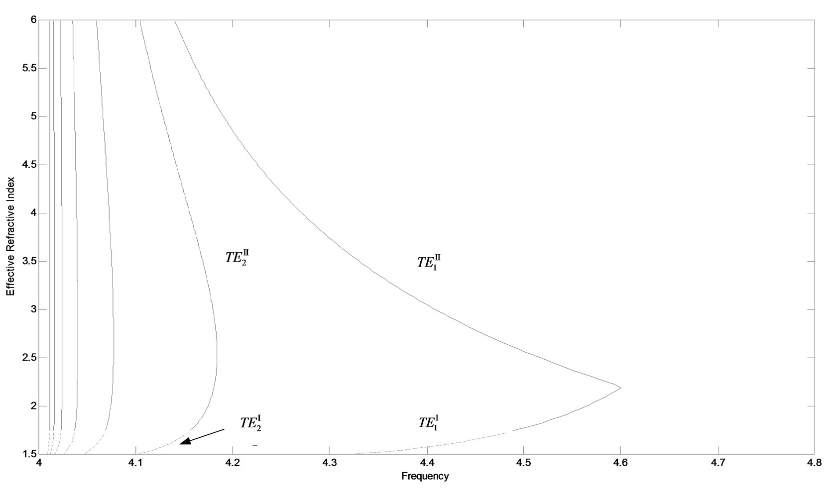
Figure 3. Dispersion curves for higher order TE guided modes, the effective-refractive-index is a function with frequency. The curves are arranged along horizontal-axis with m = 7, 6, 5, 4, 3, 2, 1, respectively. The dashed curves stand for  modes, and solid curves correspond to
  modes
modes
corresponding to the same frequency i.e. double-mode degeneracy. This is because the dispersion equation has two different solutions at the same frequency. This property can be found in other LHM slab waveguides [4,6]. Besides, its positive and negative group velocities coexist.
2) As m increases from 2 to 7, there exist six TE guided modes and their dispersion curves are plotted in Figure 3. For the same m, two types of TE guided modes exist and their curves keep continuous. As m increases, their curves shift to left and their cutoff frequencies become less. This is different from that of omitting materials dispersion [6]. For the first type  modes, their group velocities are positive. However, for the second type of
  modes, their double-mode degeneracy appears and their positive and negative group velocities coexist.
3.2 The Total Power Flux (TPF) of TE Guided Modes
Employing Equations (10)-(14) and dispersion Equations (7) and (8), we choose the same parameters as Subsection 2.1. The curves of the TPF versus frequency for TE guided modes are plotted in Figures 4 and 5, respectively. The results are as follows:
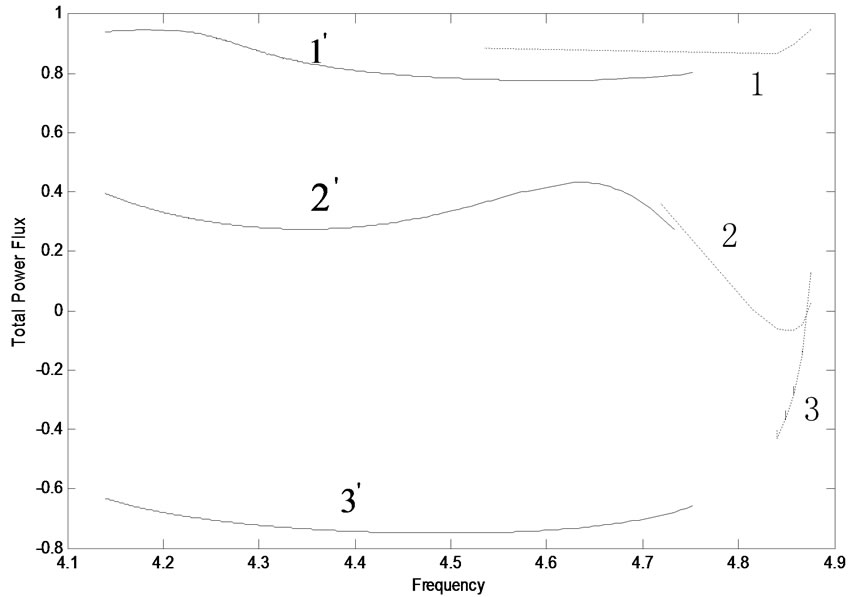
Figure 4. The total power flux of the fundamental TE mode for different slab thicknesses. The parameters are the same as Figure 2. The dashed curves stand for  modes, the solid curves correspond to
  modes
modes

Figure 5. The total power flux of the higher-order TE guided modes. The curves are arranged along horizontal-axis with m = 7, 6, 5, 4, 3, 2, 1, respectively. The dashed curves stand for  modes, the solid curves correspond to
  modes
modes
3.2.1 The Properties of the TPF of the  Guided Modes
For  and
and  modes, their TPF curves are shown in Figure 4, respectively. As h2 (1 cm) is fixed and, (1, 1’), (2, 2’) and (3, 3’) curves represent h1 = 0.1 cm, 1 cm and 10 cm, respectively. Clearly, they have a common property that their TPF becomes small with h1 increased. This is because their power fluxes in the LHM medium increases with h1, and they are negative. This makes TPF small and even negative with the increase of h1. For
  mode, as h1 < h2, its TPF changes with frequency in a smaller range. However, as h1 = h2 and h1 > h2, its TPF changes with frequencies in a bigger range. Furthermore, the TPF is positive, negative, and zero at different frequencies. Zero TPF implies that electromagnetic waves are stopped in the waveguide. This property may have some potential applications in the optical waveguide technology. For
  modes, as frequency increases, TPF changes in a small region. For both h1 < h2 and h1 = h2, TPF is positive; for h1 > h2, TPF is negative, and zero TPF doesn’t occur.
3.2.2 The Properties of the TPF for Higher Order TE Guided Modes
1) As m = 1, for  and
and  modes, their curves of TPF are plotted in Figure 5. From these curves, we find that the TPF of the former is bigger than that of the latter and they are both positive. For
  mode, its TPF decreases with the frequency. But, for
  mode, its TPF increases with frequency, then, two different TPF values exist at the same frequency. It results from double-mode degeneracy.
2) For  and
and  modes with m from 2 to 7, their TPF curves are plotted along the antihorizontal-axis in Figure 5. The former is always bigger than the latter. For
  modes, their TPF decreases as frequency increases. But, they are all positive. For
  modes, at the same frequency, positive and negative TPF coexist. It means that two modes propagate along opposite directions. At maximum frequency, zero TPF can be found for each mode.
4. Conclusions
A four-layer slab waveguide with LHM in layer 1 and RHMs in other layers has been studied numerically. The dispersion equations of two types of the TE guided modes are obtained and dispersion curves are plotted. Compare these curves, we find some dispersion properties of TE modes, such as: two types of the fundamental modes exist, moreover, in some frequency regions, they are insensitive to the waveguide thickness. Besides, the total power flux for TE guided modes is calculated and its corresponding curves are plotted. Through these curves, we find some new properties, such as: positive and negative total power fluxes coexist. At maximum frequency, we find zero total power flux. This property may find some potential applications in the optical waveguide technology.
5. Acknowledgments
This work is supported by key project of the National Science Foundation of China (60937003) and STCSM (08DZ2231100).
REFERENCES
- D. R. Smith, W. J. Padilla, D. C. Vier, et al., “Composite Medium with Simultaneously Negative permeability and Permittivity,” Physical Review Letters, Vol. 84, No. 18, 2000, pp. 4184-4187.
- A. Berrier, M. Mulot, M. Swillo, et al., “Negative Refraction at Infrared Wavelengths in a Two-Dimensional Photonic Crystal,” Physical Review Letters, Vol. 93, No. 7, August 2004.
- C. M. Soukoulis, S. Linden and M. Wegener, “Negative Refractive Index at Optical Wavelengths,” Science, Vol. 315, No. 5808, January 2007, pp. 47-49.
- I. V. Shadrivov, A. A. Sukhorukov and Y. S. Kivshar, “Guided Modes in Negative Refractive Index Waveguides,” Physical Review E, Vol. 67, June 2003.
- B. I. Wu, T. M. Grzegorczyk, Y. Zhang and J. A. Kong, “Guided modes with Imaginary Transverse Wave Number in a Slab Waveguide with Negative Permittivity and Permeability,” Journal of Applied Physics, Vol. 93, No. 11, June 2003, pp. 9386-9388
- Z. H. Wang, Z. Y. Xiao and W. Y. Luo, “Surface Modes in Left-Handed Material Slab Waveguides,” Journal of Optics A: Pure and Appli Optics, Vol. 11, No. 1, 2009, pp. 1-5
- Z. Y. Xiao and Z. H. Wang, “Dispersion Characteristics of Asymmetric Double-Negative Material Slab Waveguides,” Journal of Optical Society of America B, Vol. 23, No. 9, 2006, pp. 1757-1760.
- Y. He, Z. Cao and Q. Shen, “Guided Optical Modes in Asymmetric Left-Handed Waveguides,” Optics Communications, Vol. 245, No. 1, 2005, pp. 125-135.
- V. G. Veselago, “Electrodynamics of Substances with Simultaneously Negative Electrical and Magnetic Properties,” Soviet Physics Uspekhi, Vol. 10, No. 4, 1968, pp. 509-517.
- Y. He, J. Zhang and C. F. Li, “Guided Modes in a Symmetric Five-Layer Left-Handed Waveguide,” Journal of Optical Society of America B, Vol. 25, No. 2, 2008, pp. 2081-2091.
- L. F. Shen and Z. H. Wang, S. P. Li, “Propagation Properties for Five-Layer Symmetric Slab Waveguides Including Left-Handed Materials,” Optoelectronics Letters, Vol. 4, No. 3, May 2008, pp. 165-167.
- L. F. Shen and Z. H. Wang, “Coupling Characteristics between Five-Layer Slab Wave-Guides Including LeftHanded Materials,” Optoelectronics Letters, Vol. 4, No. 6, November 2008, pp. 419-421.
- J. Zhang, Y. He, C. F. Li and F. M. Zhang, “Guided Modes in a Four-layer Slab Waveguide with the LHM Core,” Acta Optica Sinica, Vol. 29, No. 10, 2009, pp. 2673-2680.