Journal of Electromagnetic Analysis and Applications
Vol. 2 No. 1 (2010) , Article ID: 1231 , 6 pages DOI:10.4236/jemaa.2010.21006
Research on a New Control Strategy of Three Phase Inverter for Unbalanced Loads
![]()
1Huazhong University of Science and Technology, Wuhan, China; 2East China Jiaotong University, Nanchang, China; 3Naval University of Engineering, Wuhan, China; 4Zhejiang University, Hangzhou, China.
Email: ecjtumotor@hotmail.com
Received July 24th, 2009; revised September 2nd, 2009; accepted September 7th, 2009.
Keywords: Three-Phase Inverter, Unbalanced Load, the Three-Phase Output Voltage Symmetric, Medium Frequency, P+Resonant Controller
ABSTRACT
One of the very important functions of three-phase inverter is to maintain the symmetric three-phase output voltage when the three-phase loads are unbalanced. Although the traditional symmetrical component decomposing and superimpose theory can keep the voltage balance through compensating the positive-, negativeand zero-sequence components of the output voltage of inverter, however, this method is time-consuming and not suitable for control. Aiming at high power medium frequency inverter source, a P+Resonant (Proportion and Resonant) controller which ensured a balanced three phase output voltage under unbalanced load is proposed in this paper. The regulator was proved to be applicable to both three-phase three-wire system and three-phase four-wire system and developed two methods of realization. The simulation results verified that this method can suppressed effectively the output voltage distorted caused by the unbalanced load and attained a high quality voltage waveforms.
1. Introduction
In recent decades, with the rapid development of power electronics technology and the improving requirements of electrics device performance in trades and industries, the inverter technology are increasing widespread used in multi-domain. Accordingly, there have more and more requirements for inverter power. Many electrics devices of industries are not use directly grid but inverters as their power source. Some important power-consuming departments and electrics devices, especially in high power medium frequency system, such as vessel and aircraft, require more high quality of the source, demand the voltage, frequency and waveform accurate, have a good dynamic state performance and no any disturbance from the source.
In three-phase system, however, unbalanced instances can occur in power systems for a variety of cases, such as, three imbalanced load, unsymmetrical parameters of three-phase filter, single-phase load, and so on. Unbalanced loading causes negativeand zero-sequence currents (in four-wire systems) to flow in the power system. For ideal sources this would not be a problem. However, inverter source systems, especially high power 400Hz inverter source systems, with finite output impedances, will experience voltage distortion in the form of phase voltage imbalance and phase shift due to unbalanced loading. At worst, unbalanced voltages can cause malfunction and even failure of power-consuming equipment. Thus, in inverter-fed power systems, it is the responsibility of the inverter to ensure that certain tolerances on phase voltage imbalance at the load terminals are met under specified loading conditions. Reference [1] proposed a method of extending controller bandwidth. By transforming abc to dqo, the negativeand zero-sequence components can be view as a disturbance of  and
and ![]() respectively. By utilizing controllers with bandwidths greater than the frequency of the disturbances, some attenuation will be achieved and the output voltage balance may be ensured. While this may be possible in low power 50/60Hz inverters, it would be very difficult, and likely impossible, to accomplish in high power inverters due to the difficulties of improving the switching frequency. The impossibility of this option is amplified for inverters with high output fundamental frequencies, such as the inverter under study. Reference [2] put forward a method of load current feedforward control. By using load current feedforward, the output voltage balance can be promised. In general, true feedforward assumes that the variables that are fed forward are known and independent of the controlled system. However, in the case of the load currents feedforward, the assumptions are false, because the load currents are closely coupled to the plant state variables. Thus, this feedforward control in fact forms a feedback loop. As a result, the system stability is affected and must be examined. Reference [3] proposed a double dq transform control method. Although this method can eliminate the negative-sequence component, it can do nothing for zero-sequence component. Moreover, this control strategy is time-consuming and not suitable for control.
respectively. By utilizing controllers with bandwidths greater than the frequency of the disturbances, some attenuation will be achieved and the output voltage balance may be ensured. While this may be possible in low power 50/60Hz inverters, it would be very difficult, and likely impossible, to accomplish in high power inverters due to the difficulties of improving the switching frequency. The impossibility of this option is amplified for inverters with high output fundamental frequencies, such as the inverter under study. Reference [2] put forward a method of load current feedforward control. By using load current feedforward, the output voltage balance can be promised. In general, true feedforward assumes that the variables that are fed forward are known and independent of the controlled system. However, in the case of the load currents feedforward, the assumptions are false, because the load currents are closely coupled to the plant state variables. Thus, this feedforward control in fact forms a feedback loop. As a result, the system stability is affected and must be examined. Reference [3] proposed a double dq transform control method. Although this method can eliminate the negative-sequence component, it can do nothing for zero-sequence component. Moreover, this control strategy is time-consuming and not suitable for control.
Firstly, this paper analyzed the mathematical model of the three-phase inverter and the application of the symmetrical component decomposing in engineering. As for three-phase two H-bridge units cascaded topology, a resonant controller is proposed and simulations on a three-phase 30kVA medium frequency inverter under unbalanced load are carried out. The results verified that the resonant controller can be used to satisfy completely output voltage balance under any unbalanced loads.
2. Model of Three-Phase Inverter Source and Unbalance Analysis
The topology of three-phase inverter under study is shown in Figure 1. Only phase A is presented detailedly here for the sake of space limitation. Each phase consist of DC bus voltage Ud, two H-bridge inverter, two transformer T, filter inductor L, filter capacitor C and load R which can be balanced load, unbalanced load, single-phase load, and so on. r represent the integrative effect of ESR of filter inductor, dead time of the inverter, and so on. Unipolar modulation is adopted in the single H-Bridges whose outputs are in series at secondary of
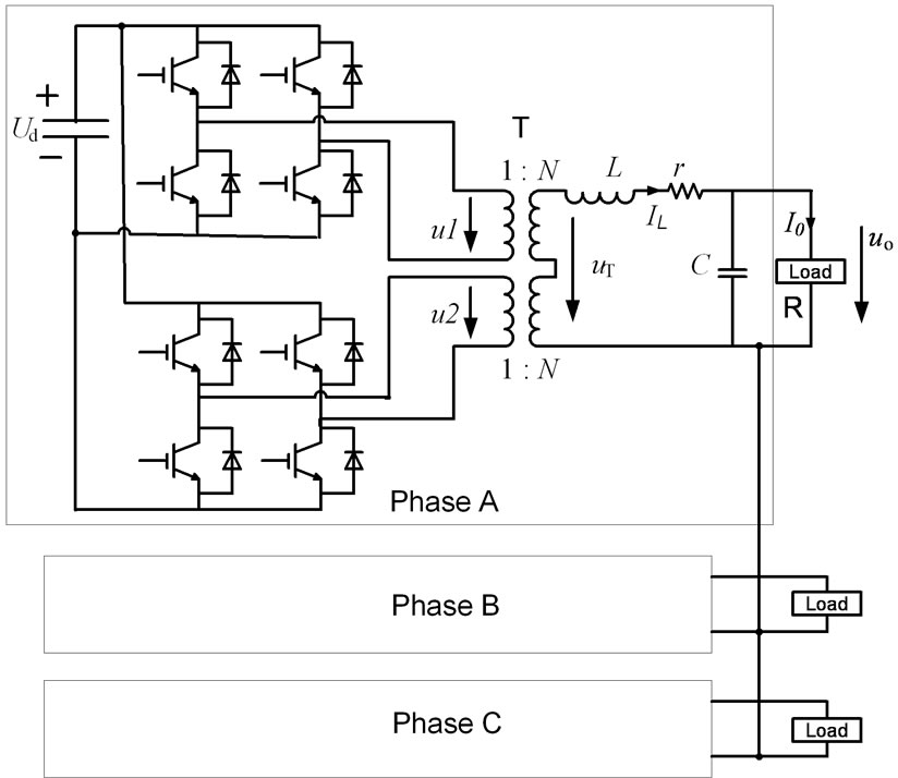
Figure 1. The two H-bridge units cascaded three-phase inverter topology
H-bridge and interleaving control is done between two two transformers. There are 90 phase degree difference between corresponding carrier waves of two H-Bridges and the modulating waves are the same, so the equivalent switching frequency of inverter is four times of the device switching frequency and the output voltage has five-level waveforms that means harmonics content in output voltage resulting from the switching is reduced.
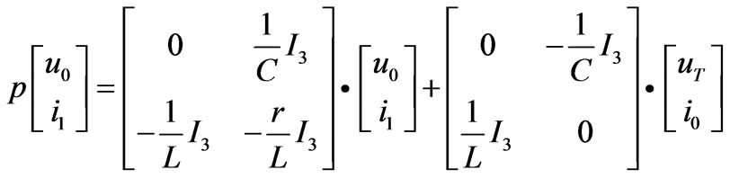
In Figure 1, uTa、uTb、uTc represent the output phase voltage of transformer, u0a、u0b、u0c represent the three voltage of filter capacitor, i1a、i1b、i1crepresent the three current of filter inductor and i0a、i0b、i0c represent the three line current. According to KCL and KVL, Formula (1) can be written out:
 (1)
(1)
where ![]() denotes differential operator,
denotes differential operator, 
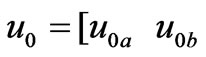 denotes the output voltage vector of inverter,
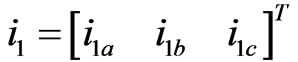 denotes current vector of filter inductor,
  denotes the output voltage vector of transformer,
  denotes the current vector of load and I3 denotes a unit matrix of three by three.
If u0a、u0b、u0c and i1a、i1b、i1c were taken as state variables, then Formula (1) and (2) make up of the plant state equation of Figure 1.
 (2)
(2)
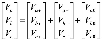
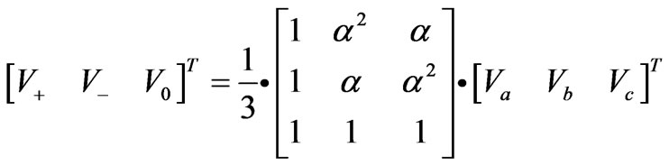
Unbalanced output phase voltages or currents phasor can be symmetrically decomposed into their positive-, negativeand zero-sequence components. Assume Va, Vb and Vc represent three phase voltage phasor, then:
 (3)
(3)
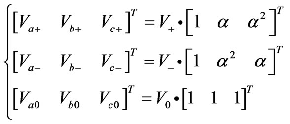 (4)
(4)
 (5)
(5)
where , subscript a, b, c represent three
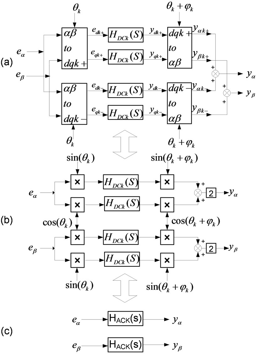
Figure 2. Resonant controller of three-phase system
phase electricity respectively, subscript +, -, 0 represent positive-, negativeand zero-sequence components respectively.
3. Resonant Regulator
It is known from analysis aforementioned that due to near zero impedance which ideal sources possess, the voltage dropping of impedance caused by negativeand zerosequence current components due to unbalanced load is almost zero and unbalanced load has little influence on ideal sources. So if the output voltage of inverter is not suffer from the unbalanced load is expected, the output impedance of inverter source must be near zero too. It is known from control theory that if a near zero impedance of a system is expected, the open loop gain of the control system must be attain infinite at certain signal frequency.
3.1 Resonant Controller with  as Input and Output Variable
Figure 2 is the resonant controller of three-phase system. By transforming abc to αβ, the output voltage errors of abc coordinate can be transfer to αβ coordinates variable . Following the scheme of Figure 2(a), the output voltage errors
  in
in  coordinates are first converted into synchronous reference frame quantities
 ,
, 
 using both positive-
 and negative-
 sequence transformations rotating at angular frequency
 (i.e.,
 ,
, ) where
  is the order of the generic harmonic to be compensated and
 ![]() is the fundamental angular frequency. All synchronous reference frame errors
is the fundamental angular frequency. All synchronous reference frame errors
 are then compensated by regulators HDCk(S), which ensure zero steady-state errors for each positiveand negative-sequence harmonic component. Then, the output of each regulator
 is converted back to the stationary reference frames and possibly adding a leading angle
  which compensates for the delay of the remaining process. The structure is complicated which need compensate for each order harmonics including positiveand negativesequence components. Moreover, coupling may be exist between the d and q axis variables.
There will exist zero-sequence component if the three-phase system is imbalanced. Of course, any possible zero-sequence component cannot be compensated in Figure 2. However, zero sequence component can be control by the resonant controller also. This will be discussed later.
Some simplifications of the theoretical scheme of Figure 2(a) are possible [4,5]. First, it is easy to verify that the compensation of both positiveand negative-sequence harmonic components for a generic harmonic  is equivalent to the synchronous demodulation of the
  components, shown in Figure 2(b), as long as all regulators HDCk(S) in Figure 2(a) and (b) have the same transfer function. Secondly, even the scheme of Figure 2(b) can be further simplified since it is equivalent to the scheme of Figure 2(c) with stationary-frame regulators HACk(S). The proportion term can be put outside the transform due to the proportion is same in stationary reference frame and synchronous reference frame.
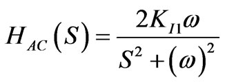
By deducing, the transform formula HACk(S) is [4]:
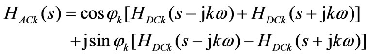 (6)
(6)
If
 (7)
(7)
Then
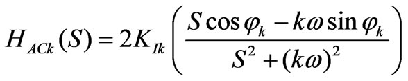 (8)
(8)
If the delay compensating is not take into account in Formula (8), then
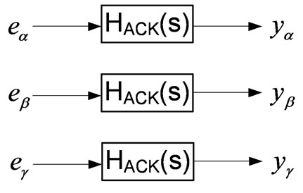
Figure 3. Control block of three-phase four-wire system
 (a)
(a)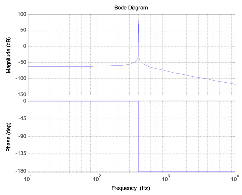 (b)
(b)
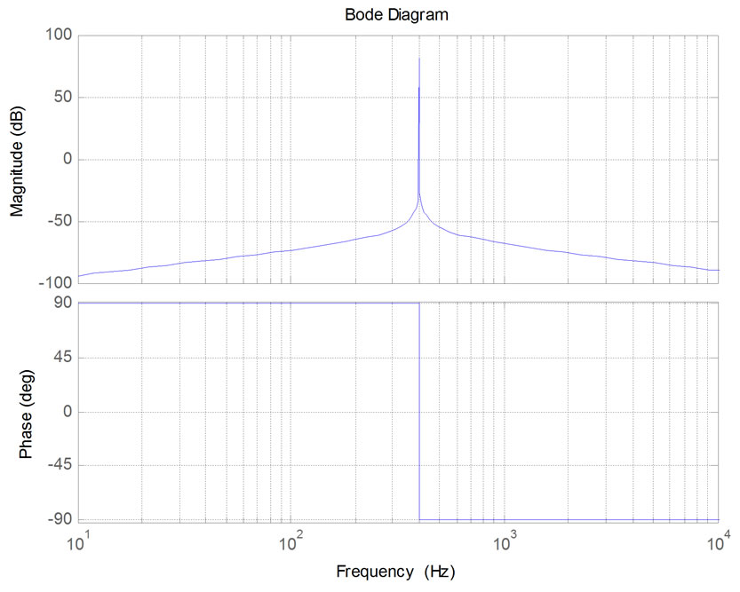
Figure 4. Bode plot of resonant regulator(KI1=1,ω=800π). (a) Bode plot of (9) where k=1; (b) Bode plot of (11)
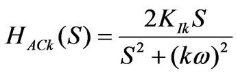 (9)
(9)
where ω denotes the fundamental frequency of reference signal,  denotes order of harmonics, KI denotes the gain of integral term.
It is known from [6] that when the load is unbalanced load or nonlinear load and a balance of output voltage is expected, which means the zero sequence component need be compensated, a three-phase four-wire system must be adopted. In Figure 2, however, only αβ axis are taken into account. If the system is a three-phase fourwire system,  axis also need be thought over. It is known from coordinate transform theory that αβ axis variable are positiveand negative-sequence component and
  axis variable is zero-sequence component. The method shown in Figure 2(a) can be used to process the positiveand negative-sequence component of αβ axis and the method shown in Figure 2(b) can be adopted to deal with the zero-sequence component of
  axis. i.e. resonant controller can be used to deal with all
  axis variable. The control block is shown in Figure 3.
The matrix form is shown in Formula (10)
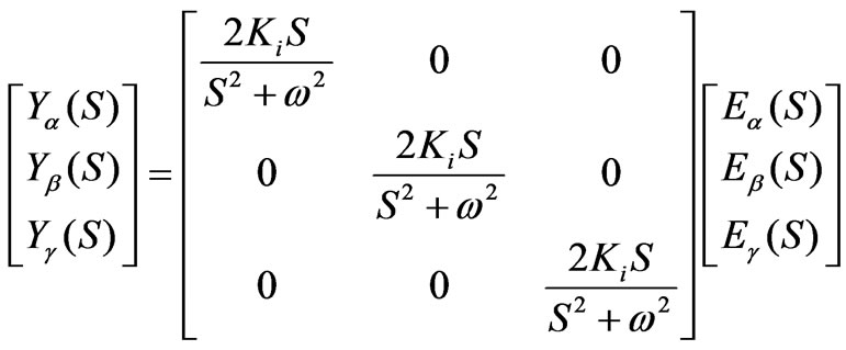 (10)
(10)
It is can be seen from (10) that the term of non-diagonal is zero which means there are no coupling among  variable and can be decoupled as singlephase.
The bode diagram of Formula (9) where k is equal to one is shown in Figure 4(a). It can be seen from Figure 4(a) that the regulator has an infinite gain (it is a finite value in the bode diagram due to simulation step and truncation error) at certain frequency. Then the gain of open loop which including the resonant controller will achieve infinite(as for unit negative feedback system, the gain of open loop is equal to transfer function of controller multiply transfer function of object) and zero steady state error between output voltage and reference voltage can be promised.
It is also noted that the controller presented in (9) has a transfer function similar to that presented by Sato et al. [7], which has a resonant transfer function given by
 (11)
(11)
Sato’s transfer function also has infinite gain at the resonant frequency and hence can be used to suppress the output voltage distorted caused by the unbalanced loads. However, it in particular introduces a phase shift of 180 into the system, compared to the 90 shift of the P+Resonant system, as illustrated in Figure 4(b). In closed loop operation this 180 phase shift results in a poorer phase margin and a poor transient performance for this regulator compared to the approach presented here.
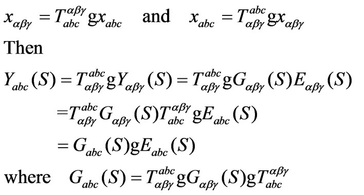
3.2. Resonant Controller with ABC as Input and Output Variable
The resonant controllers which induced before are with  as input and output variable. However, practical three-phase systems are with abc as input and output variable. The deduction of the relations of controller with abc as input and output variable and controller with
  as input and output variable is shown as follows:
It can be know from stationary coordinate transformation theoretics,
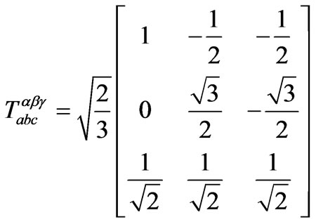 (12)
(12)
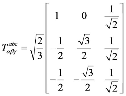 (13)
(13)
So the relation of variable in abc coordinate and variable in  coordinate is:
 (14)
(14)
If 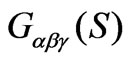 equal to Formula (10)Then
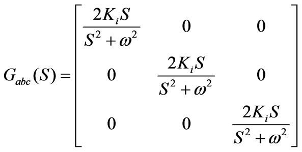 (15)
(15)
It can be seen from (15) that the element of non-diagonal is zero, which means there are no coupling among abc variable and can be decoupled as single-phase.
It must be emphasis on that the system must be threephase four-wire system when apply Formula (10) or (15). This is because zero-sequence component can only be compensated in three-phase four-wire system. As for three-phase three-wire system, Formula (10) or (15) can not be used directly. However, by weeding the zero-sequence component of feedback variable and ensuring the input variable of  axis equal to zero, Formula (10) or (15) can be used in three-phase three-wire system. Moreover, in general, line to line voltage can only be gotten in three-wire system and phase voltage which educed from line to line voltage satisfy automatically the condition that input variable of
  axis equal to zero.
4. Simulation Investigations
In order to illustrate the resonant controller is effective on unbalanced load, the proposed control strategy has been investigated using MATLAB/Simulink simulations on both three-phase three-wire system and three-phase fourwire system. The load is Y or Yn connected and loads of phase A, B and C are 1.5Ω, 1.5Ω and 15Ω respectively. Table 1 defines the parameters used in simulations.
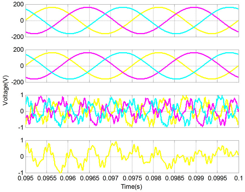
The output voltage waveforms of three-phase four-
 (a)
(a)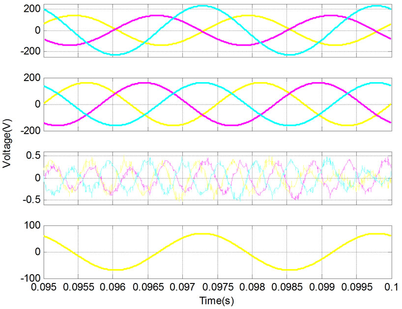 (b)
(b)
Figure 5. Output voltage waveforms under resonant controller(from up to down are in turn three-phase voltage, positive-, negativeand zero-sequence components of output voltage). (a) Three-phase four-wire system; (b) Three-phase three-wire system
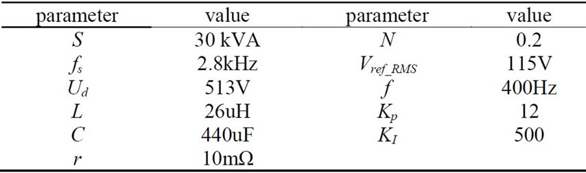
Table 1. Simulation parameters of the system
 (a)
(a)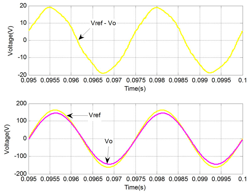 (b)
(b)
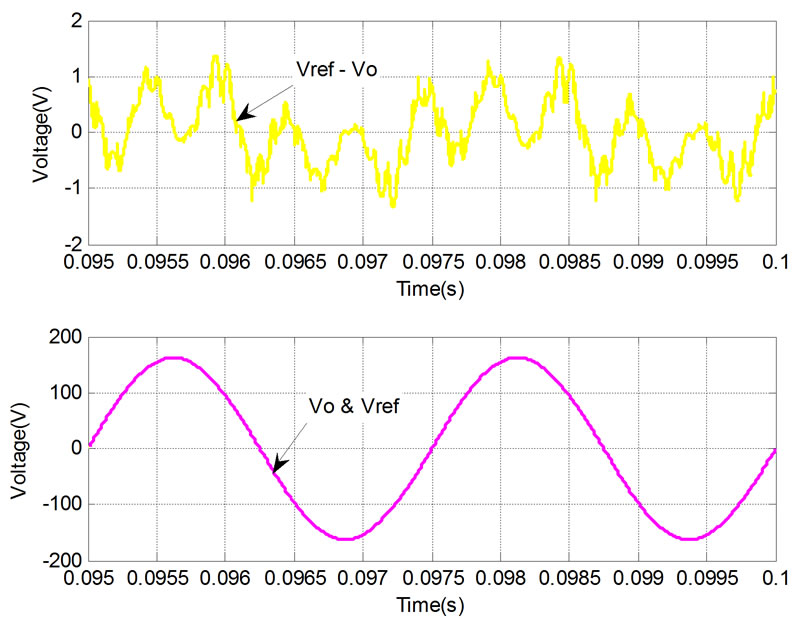
Figure 6. Error voltage and output voltage, reference voltage waveforms of three-phase four-wire system. (a) Resonant controller; (b) Proportion controller
wire and three-phase three-wire system under resonant controller are shown in Figure 5(a) and (b) respectively. It can be seen from Figure 5(a), that the negativeand zero-sequence component can be depressed by resonant controller in three-phase four-wire system. It can be seen from Figure 5(b) that only negative-sequence component can be depressed by resonant controller in three-phase three-wire system. There are still positiveand zero-sequence component in output voltage (positive-sequence component is system need, zero-sequence component is system didn’t need but remaining due to the three-phase three-wire configuration).
The error voltage and output voltage Vo, the reference voltage Vref waveforms of three-phase four-wire system under resonant controller are shown in Figure 6(a). It can be seen from (a) that the error is almost zero and the output voltage is superposition with reference voltage which proved the correct of analysis aforementioned. In order to compare, Figure 6(b) gave the waveforms under proportion regulator. It can be seen from (b) that there are obvious steady state amplitude and phase error between the reference voltage and the output voltage.
5. Conclusions
This paper analyzed the output voltages distortion mechanism under unbalanced load, a three-phase two Hbridge units cascaded topology is presented and the equivalent switching frequency of inverter is improved effectively. A P+Resonant controller which ensured a balanced three phase output voltage under unbalanced load is proposed for high power medium frequency inverter sources. The regulators proved to be applicable to both three-phase three-wire system and three-phase fourwire system and two methods of realization were developed. The simulation results verified that this method can suppressed effectively the output voltage distorted caused by the unbalanced load and attained a high quality voltage waveforms.
REFERENCES
- R. A. Gannett, “Control strategies for high power four-leg voltage source inverters,” Virginia Tech, 2001.
- R. Zhang, “High performance power converter systems for nonlinear and unbalanced load/source,” Virginia Tech, 1998.
- P. Hsu and M. Behnke, “A three-phase synchronous frame controller for unbalanced load,” IEEE-PESC’98 Record, Fukuoka, Japan, Vol. 2, No. 5, pp. 1369–1374, 1998.
- P. Mattavelli, “Synchronous-frame harmonic control for high-performance AC power supplies,” IEEE Transaction on Industry Applications, Vol. 37, No. 3, pp. 864–872, May/June 2001.
- D. N. Zmood and D. G. Holmes, “Stationary frame current regulation of PWM inverters with zero steady state error,” Proceedings of PESC’99, SC, USA, pp. 1185– 1190, 1999.
- C. Sun, W. M. Ma, and J. Y. Lu, “Analysis of the unsymmetrical output voltages distortion mechanism of three-phase inverter and its corrections,” Proceedings of CSEE, Vol. 26, No. 21, pp. 57–64, November 2006.
- Y. Sato, T. Ishizuka, K. Nezu, and T. Kataoka, “A new control strategy for voltage-type PWM rectifiers to realize zero steady-state control error in input current,” IEEE Transactions on Industry Applications. Vol. 34, No.3, pp. 480–486, May/June 1998.
NOTES
Project Supported by National Nature Science Foundation of China (50607020), (50737004ZD) and (50721063).