Int'l J. of Communications, Network and System Sciences
Vol. 5 No. 11 (2012) , Article ID: 24673 , 14 pages DOI:10.4236/ijcns.2012.511079
Dynamic 3-D Indoor Radio Propagation Model and Applications with Radios from 433 MHZ to 2.4 GHz
Computational Science, University of South Carolina Beaufort, Bluffton, USA
Email: yimingji@uscb.edu
Received August 18, 2012; revised September 28, 2012; accepted October 8, 2012
Keywords: WiFi; RFID; Radio Propagation Model; Location Based Service; Signal Strength
ABSTRACT
Proliferation of indoor sensor infrastructure has created a new niche for mobile communications, yet research in indoor radio propagation still has not generated a definite model that is able to 1) precisely capture radio signatures in 3-D environments and 2) effectively apply to radios at a wide range of frequency bands. This paper first introduces the impact of wall obstructions on indoor radio propagation by experimental results through a full cycle of an indoor construction process; it then exploits a dynamic 3-D indoor radio propagation model in a two-story building using radio technologies at both 433 MHz and 2.4 GHz. Experimental measurements and evaluation results show that the proposed 3-D model generates accurate signal strength values at all data evaluation positions. Comparing the two radio technologies, this study also indicates that low frequency radios (such as 433 MHz) might not be attractive for indoor mobile computing applications because of larger experimental errors or constant absence of measurement data.
1. Introduction
When Mark Weiser first coined the phrase “ubiquitous computing” around 1988 [1,2], the idea of “information available at our fingertips during a walk” was stilla dream. Today, through relentless pursuit of innovations in wireless communication and energy efficient hardware technology, we are gradually turning this dream into reality. Smart phones and tablets, enabled with adaptive software, have generated lucrative revenues for business and thus have inspired numerous waves of research efforts in mobile computing. In this context, location-based services have attracted considerable attention because of their potential to empower mobile computing with highly personalized and context-aware services [3,4]. However, there still exist considerable challenges, particularly in indoor location determination. As suggested by Mahadev Satyanarayanan [5], this challenge embodies a number of themes that could be central to the evolution of mobile computing. This paper continue sour previous research [6-12] and develops and evaluates a 3Dindoor radio propagation model that will not only help understand radio propagation in complex indoor environment but also contribute a set of genuinely applications that depend on real-time radio propagation signatures for a wide range of radio frequencies.
Indoor location determination typically uses a range of technologies in order to overcome constraints of indoor structures and environments. These technologies include: 1) infrared [13]; 2) sound [14-17]; 3) vision [18-21]; 4) inertial sensors [22,23]; 5) radio frequency (including both WiFi and Zigbee) [6,10,24-33]; and 6) landmarks [34-37]. High-sensitivity GPS sensors have also been evaluated in indoor environments, however, even with the ability to receive signals up to 1000 times weaker than normal GPS, high-sensitivity GPS receiver is still unreliable for indoor environments [38,39]. Among these technologies, however, most location determination systems used only one or a combination of three localization techniques:
1) Trilateration/Triangulation or Area Overlapping [40-51], where distance, angle, or area information from a mobile to known reference positions is used to estimate the mobile’s position.
2) Location Fingerprinting [6,10,16,26,33,52-58], where location dependent information signatures (i.e. fingerprints like signal strength, image, sound, or other unique information) are pre-collected and evaluated against current measurements in order to pinpoint the location of a mobile.
3) Dead Reckoning (DR) [22,23,59-62] that determines, without the aid of external observations or references, the position and/or orientation of a mobile client from the record of traveled courses, distance and drift angles.
Trilateration/triangulation involves less overhead for offline training processes; however, it requires high resolution sensor devices in order to obtain accurate distance or angle measurements between mobile and reference positions. In reality, indoor radio waves from non-lineof-sight paths may result in a stronger signal than radio from a shorter path or even a direct path. This multipath problem could result in an average of 8.5 meters of range estimation errors and is “not able to be solved or even mitigated by simply increasing the bandwidth of the signal transmission” [63]. Consequently, for more than a decade, researchers have been trying to identify alternative approaches that correlate less with multipath radio propagation. Dead reckoning is obvious a good choice, and is gaining more interest lately because of the advance of sensor technology. But it is still difficult to apply this method for low-speed (orpedestrian-based) indoor mobile computing. Therefore, location fingerprinting could be considered to be a promising method, but the key issue is that it requires the construction of a database table to map radio propagation signatures (such as signal strength, images, or sound) with location coordinates. Usually, database construction process is labor intensive and is generally not updatable in real-time applications.
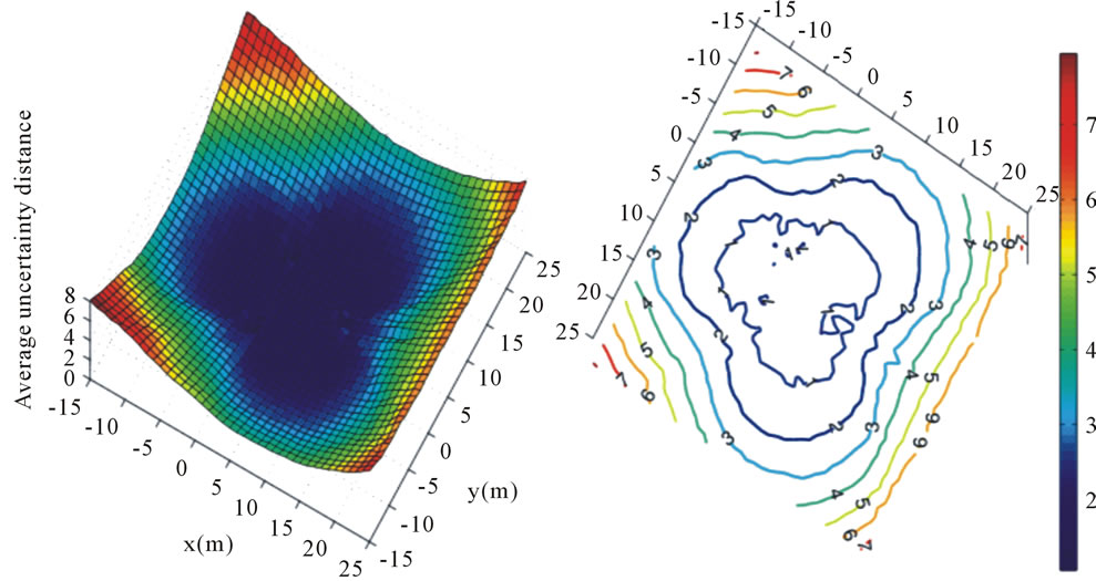
Consequently, research community has been focusing on identifying an effective and precise indoor radio propagation model [6,24,64-69] that would make the database construction an automated process. Among those models, ARIADNE [6] is one of promising radio models that could be used to build dynamic database to map location coordinates with radio signatures (such as signal strength values from reference transmitters) for the changing environment. For example, Figure 1 shows an example in a rectangular space with 40 × 40 meters that uses signal strength values (dynamically estimated by ARIADNE) for location determination (indicated by the vertical axis). In this example, three reference radio transmitters form an equilateral triangle in the space. The figure shows that better localization results could be achieved when the user is located within or near the area of the equilateral triangle. Figure 1(b) gives a corresponding contour representation of the localization performance (in meters) for the space, and it clearly indicates that within and/or around 1.0 meter localization error could be easily achieved at locations that are covered by three reference radio transmitters. Obviously, real-time radio propagation model that correctly estimates radio propagation signatures is a key factor for the performance of location determination.
We believe simple 2-D signal-location maps may not be sufficient for complex3-D environments. As indicated in Figure 2, if a signal-location map is constructed on a horizontal plane at a distance above the floor, then signal strength measurements for mobile clients at different heights (by Δhi, i = 1, 2) may be misrepresented by values at others locations roughly δi (i = 1, 2) away from their true (horizontal) positions. Moreover, for a large floor-plan or a 3-Dbuilding, simple representation of signal-location map with uniform grid distance at both directions in a 2-D plane (or three directions for 3-D buildings) may not be efficient. Therefore, a more advanced 3-D radio model must be exploited in order to provide comprehensive radio signatures, in real time, for various mobile computing applications.
More importantly, although research community has already applied both WiFi 802.11 technology (at 2.4 GHz) [6,25,26,31,53,55-57,70] and RFID1 devices at lower frequency bands (433 MHz - 928 MHz) [36,71-77] in indoor localization research, there is still no clear conclusion on two major issues:
1) Which radio technology works more robust and effectively in indoor environment?
2) Is there a common radio propagation model that works effectively for radio technologies from 433 MHz to 2.4 GHz?
There have been a few studies that compare these wireless techniques. For example, Valenzuela [78] explored signal measurement techniques for radio transmission at 900 MHz and 2 GHz. Ali-Rantala et al. [79] studied indoor radio propagation at both 2.45 GHz and 433 MHz and concluded that 433 MHZ band is a good choice for wireless applications due to its advantages of low power consumption and large fractional coverage. Alvarez et al. [80] implemented the ZigBee system based on received signal strength for 433 MHz, 868 MHz, and 2.4 GHz frequency bands. However, the study used only a free-space model, and the evaluation was conducted in a limited space inside an industrial warehouse.
Additionally, it did not take into consideration radio attenuation effects from walls. To this date, majority research and applications mainly focus on a 2-Denvironment without considering effective radio transmission range and radio attenuation performance through floors (i.e., vertically instead of horizontally), and therefore the application of those systems in 3-D space is still not evaluated.
In this research, we first introduce an interesting experiment during an indoor construction process where radio attenuation was measured at different stages of wall construction. We then study a realistic 3-D radio propagation model to approximate radio propagation in an indoor environment. We also conduct field measurements using both WiFi (at 2.4 GHz) and RFID radios (at 433 MHz) in a two-story academic building and evaluate the effectiveness of both radio technologies in indoor wireless applications. The remainder of the paper is or-
 (a) (b)
Figure 1. Localization performance against reference transmitters.
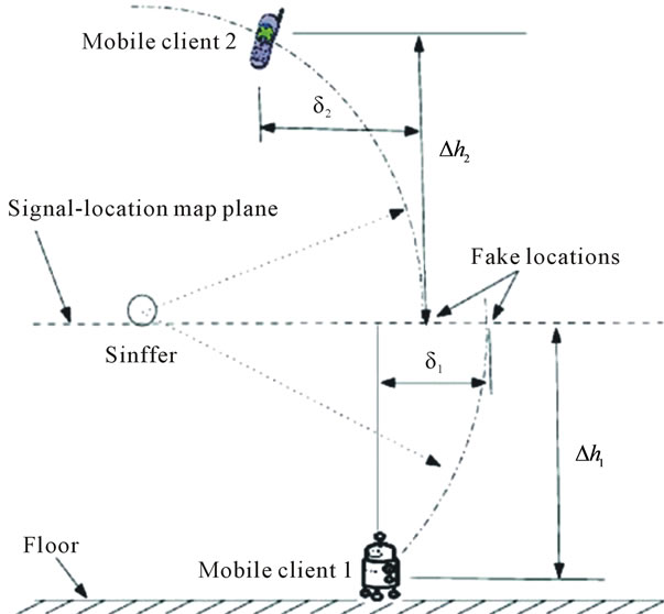
Figure 2. Localization errors using 2-D map.
ganized as follows: Section 2 gives measurement results through a full cycle of an indoor construction process, Section 3 introduces the 3-D radio propagation model, Section 4 presents experimental and evaluation results in a two-story building, Section 5 discusses key issues and/or parameters critical to the indoor radio propagation, and Section 6 concludes the paper and outlines future research.
2. Radio Attenuation from Wall Partitions
Indoor radio propagation is complex, and to estimate radio signal strength, researchers have tried to identify a “super” attenuation exponent n for the log power model (Equation (1)) based on the distance to the radio transmitter [64,68,69]. Similarly, other researchers proposed that radio attenuation comes from both the distance and (wall) obstructions, where obstruction attenuation is determined by the multiplication of an attenuation factor WAF with the total number of (wall) partitions C between the receiver and the radio transmitter, see Equation (2) [24,66].
 (1)
(1)
where P(d), in dBm, is the power at distance d to the transmitter in meters; P(d0) is the power at a reference distance d0, usually set to 1.0 meter.
 (2)
(2)
where C is the total number of obstructions (wall partitions) and WAF is the wall attenuation factor.
In order to understand the intriguing nature of the indoor radio propagation, we conducted signal measurement during a remodeling process of an academic building at the University of South Carolina Beaufort. As indicated in Figures 3 and 4, the remodeling process involved the construction of four offices from an open space. We placed a radio transmitter in one of the rooms, and recorded radio signal strength values at three neighboring rooms (see Figure 4). The experiment took roughly eight months (from March to October, 2011), and we compared signal strength values at four major stages along with progress of the construction. The four stages include: 1) initial aluminum frames for walls (Figure 3(a)); 2) one side dry wall with aluminum frames; 3) one side dry wall with insulation material (Figure 3(b)), and 4) completed dry walls and finished ceiling. We show measurement results in Figure 5.
 (a)
(a) (b)
(b)
Figure 3. Wall structure.


Figure 4. Radio propagation through neighboring rooms.

Figure 5. Radio signal strength measurements at locations with different obstruction walls.
The top figure of Figure 3 gives a section view (without ceiling) of the 3 D office environment. In the experiment, receiver’s positions in rooms ♯2 and ♯3 are symmetric to the room for the transmitter, and room ♯1 is on the far left, with room ♯2 in the middle, of the transmitter. Figure 5 gives measured (average) signal strength values (y-axis) at three rooms (x-axis). We show measurement uncertainty using standard deviation among all measurements during the data collection process.
Figure 5 shows that: 1) severe attenuation from wall obstructions was clearly observed, signal strength values at room ♯3 are much lower than those from the other two rooms, especially for measurements from both “finished walls” and “one-side dry wall with insulation material”; 2) distance contributes minor attenuation, when only aluminum frame was set up (without drywall on either side), radio signal strength at three rooms are similar; 3) positions with similar wall obstructions and distance to the transmitter have similar radio signal strength values, in the figure, measurements from rooms ♯1 and ♯3 are very similar to each other; and 4) the ceiling structure may potentially increase radio signal strength for locations that are close to the transmitter. Measurements from room ♯2 and ♯3 show that radio signal strength values from the “finished dry walls and finished ceiling” are much higher than other scenarios. On the other hand, because of the larger distance between room ♯1 and the transmitter, potential contribution from the ceiling is not obvious in room ♯1. This may suggest that reflected radio rays from the ceiling may not be able to reach the receiver because of (extra) wall obstructions along the (long) propagation path. Therefore, we believe that simple distance or obstruction based models (Equations (1) and (2)) may not be able to capture the essence of the indoor radio propagation. We consequently use ray tracing method in this research.
3. Ray Tracing and Proposed Radio Propagation Models
In order to simulate indoor radio wave propagation and penetration, ray tracing methods have been widely investigated [81-83] and various computational methods [84- 87] have also been developed to improve both computational efficiency and accuracy. Basically, ray tracing is derived from geometrical optics.
It assumes that radio energy from a transmitter is disipated and radiated in an infinite number of extremely small tubes (or rays) that are transmitted independently. The receiver collects rays from direct, reflected, and refracted paths and the energy from these rays determines the final radio energy at the receiver position. An example of ray tracing in a two story building is given in Figure 6; in the example, three axes represent the dimension of the building in meters, the radio transmitter is located on the first floor and the receiver on the second. In order to demonstrate the concept, the figure only includes rays with up to two reflections. In order to determine radio energy at a receiver, each ray from the transmitter must be traced. However, as evidenced in Figure 6, each ray may travel different distances because of reflections. In addition, each ray may have a different phase shift value and may experience a different attenuation rate through a different number of walls and/or media. Consequently, a
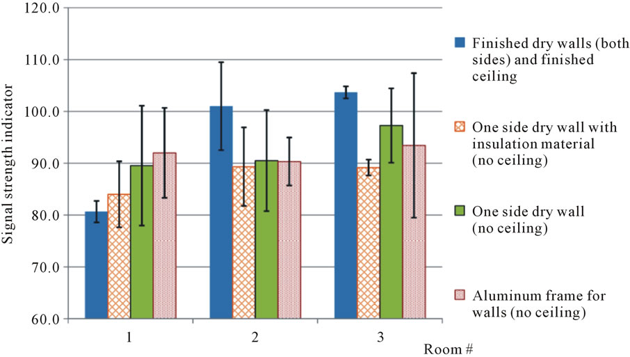
Figure 6. Ray tracing in the two-story USCB S&T building.
complex impulse response at the receiver is usually modeled as [64]:
 (3)
(3)
where  and
and  are real amplitudes and excess delays, respectively, of the ith ray component at time t.
  represents overall phase shift, and N istotal number of time-delayed impulse components.
Considering small-scale fading and multipath wave effects, the average radio energy at the receiver over a local area is given by:
 (4)
(4)
where the over bar denotes time average for the measurements over the local area and rij is the path amplitude correlation coefficient. When multipath impulse components are identically and independently distributed over [0, 2π] or when the path amplitudes are uncorrelated,  and/or rij = 0, this results in the average radio energy and is “simply the sum of the average powers received in each multipath [impulse] component” [64] (page 187).
Consequently, in order to determine the average radio energy at a receiver when considering phase-shifted and attenuated rays from different propagation paths, Ji et al. [6] proposed the following model:
 (5)
(5)
where E is the radio energy at the receiver, Nr,j is the total number of rays received at receiver j; E0 is the radio energy at a reference distance; di, Ni,ref, and Ni,trans represent radio transmission distance, total number of reflections, and total number of wall transmissions by the ith ray, respectively. γ is the reflection coefficient and α is the transmission coefficient.
Equation (5) works very well in single-floor buildings [6,7,9] although it assumes similar transmission attenuation through all partitions. For buildings with non-uniformly partitioned structures, [88] proposed a method to adapt the model for other types of partitions such as (construction supporting) columns, bookshelves, and floors. Basically, the authors suggested the use of multiple [regular] walls to represent a particular structure (such as a supporting column). For example, if the cross section of a uniform rectangle construction column is 0.6 m × 0.4 m in x and y directions, and the thickness of a wall is 0.2 m, then the column may be modeled as 3 continuous walls in the x direction and 2 walls in the y direction. Similarly, a floor may be considered as a stack of multiple walls. However, this is a trial-and-error method, and because the construction material of different partition structures could be very different, this intuitive method may not work well in general. Moreover, the evaluation of this method using signal measurements from multiple-floor environments is still not available.
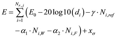
For this reason, in this paper we slightly modify the model in Equation (5) to specifically include a floor attenuation factor, in the format of the following equation:
 (6)
(6)
where α1 and α2 represent, respectively, the transmission attenuation coefficient for walls (Ni,W) and for floors (Ni,F), and  is a zero-mean Gaussian distributed random variable with standard deviation σ.
We believe, by counting all potential rays from various paths, our model effectively captures the nature of the radio reception at the receiver. And therefore, this model would work similarly for radios at a wide range of frequency bands. In order to prove the concept, we will apply both models (in Equations (5) and (6)) in a two-story academic building. We will deploy two different radio technologies (WiFi at 2.4 GHz and general RFID at 433 MHz) in the building and evaluate the performance of radio propagation utilizing field measurements.
4. Experiments and Evaluation
4.1. Building Environment, Wireless Devices, and Experimental Strategy
The two-story Science and Technology Building (see Figure 7) at the University of South Carolina Beaufort was used in this study. The left figure shows atop view of the floor plan, the right figure shows a 3-D view of the building with radio transmitters and mobile receivers at data validation positions on both floors. The radio transmitters are represented by blue dots and the data validation positions (receiver) are denoted by red stars. The two floors of the building have a similar structure; classrooms are located in the center of the building, the east side of the building is designed for faculty office space, and most other areas are used for science laboratories (first floor)—including Biology, Chemistry, and Physics—as well as various nursing laboratories on the second floor. In this building, we deployed 20 radio transmitters (RFID or WiFi); 10 for each floor at the same horizontal plane. Figure 8 shows a measurement and deployment example using RFID devices where an RFID tag was placed in an envelope on the wall. We then measured radio signal strength at 16 data evaluation positions (8 for each floor). The left image of Figure 8 shows a measurement scenario at one of the data verification positions. Note that the RFID radio transmitters were placed at a greater height than the reader (see Figure 8), and we did not distinguish this in the right figure of Figure 7 where transmitters and readers were placed on the same hori-
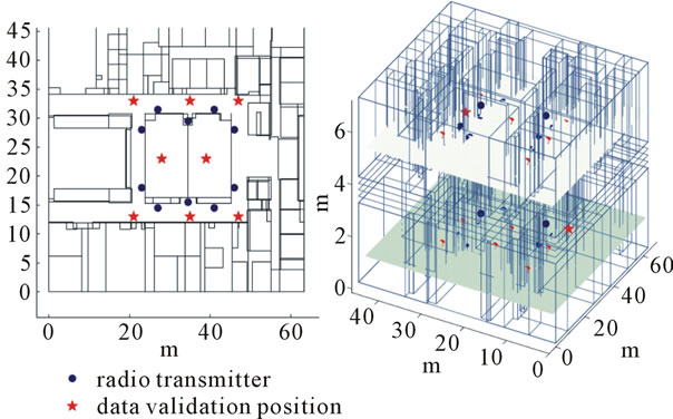
Figure 7. Two-story S&T building used for experiments.
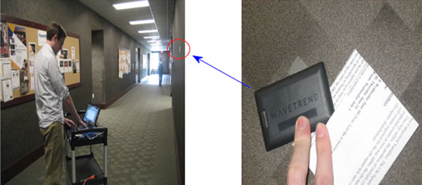
Signal strength measurement Wave trend RFID tag and envelope
Figure 8. Signal strength measurement using RFID.
zontal plane of both floors for illustrative purposes. On the other hand, for experiments using WiFi radio technology, the transmitters and readers did reside on the same horizontal plane.
We used the following hardware components in experiments:
1) RFID devices (Radio frequency at 433.92 MHz):
a) Wave trend active tag (TG501) with up to 100 meters transmission range [89].
b) Serial reader (RX201-RS232/485) with AN100 antenna, which is an omni-directional reception antenna with a maximal sensing range of 40 meters.
2) WiFi devices (Radio frequency at 2.4 GHz):
a) Lenovo Thinkpad T60 as receiver, this laptop includes an Intel T25002.0 GHz Core Duo processor with Intel PRO/Wireless 3945ABG (802.11 a/b/g).
b) Dell Latitude E6400 as transmitter, this laptop includes an IntelCore 2 Duo P9500 processor with Intel 5100 802.11 a/b/g/Draft-N Wireless Card.
c) With both radio technologies at different frequency bands, we measured radio signal strength values at all data validation positions as indicated in Figures 7 and 8. We then evaluated the two radio propagation models with Equations (5) and (6).
For the original model in Equation (5), we first applied the model to a single floor without considering the impact from the second floor. In this case we had to apply the model twice, one for each floor. Secondly, we intuitively considered the floor as multiple walls and applied the model for the entire building. In this case, we only needed to apply the model once. Since the modified model in Equation (6) was designed for 3-D environments, we were able to apply the model to the entire building directly.
4.2. Measurement and Evaluation Results
Extensive measurements of WiFi and RFID signal strength values were collected from the building, and we noticed that the RFID reader/tag presented a slight surprise. First, the RFID serial reader could not receive tag signals from the other floor. Note that the RFID tag (TG501) is able to transmit radio signals up to 100 meters, and the reader has a sensing range of 35 meters.
This phenomenon probably indicates that the floor imposed severe attenuation effects to RFID signals (at 433.92 MHz) resulting in a radio signal too weak for the reader. Second, tag signals were not particularly stable. This was evidenced by constant absent signals in data measurement. On the contrary, WiFi signals appeared to be relatively stable and able to transmit through floors. In addition, RFID signal presented much higher measurement uncertainty during the experiment.
Figure 9 shows example measurement results using both WiFi and RFID at 10 different locations on a floor. We used the standard deviation among all measurements at a location to show the average measurement uncertainty for both radio technologies. The figures clearly shows that RFID gives much higher measurement uncertainty, and thus it indicates that while RFID technology is widely used in many industries to track objects, it does raise concerns if it would be used for projects that are mission critical and/or involve large amount of data where absent signals and/or noisy measurement could significantly degrade the processing time and system performance.
In order to evaluate the application of the model to the RFID radio technology at 433.92 MHz, because of its short transmission range, we applied the2-D radio propagation model (in Equation (5)) individually at each single floor. For the WiFi radio, however, we considered the building as a single unit and evaluated both models, i.e., Equation (5) using the empirical method given in [88] and Equation (6) for the entire building.
Figure 10 gives an example of RFID signal strength values (y axis) at all data evaluation positions on the first floor. Each sub-figure corresponds to a receiver at a data evaluation position and each receiver would ideally receive ten radio signals from ten radio transmitters (or RFID tags, displayed on the x axis). The red circles represent estimated signal strength and blue asterisks denote the measured values. Note that the receiver missed one radio signal at data evaluation positions 1, 3, 4, and 7 (see sub-figures titled with “Receiver 1”, etc.). For this example using RFID radio at 433.92 MHz, an average absolute error of 6.4885 and average relative error of 7.65% were achieved by using the radio propagation model in Equation (5). This result was consistent for both floors, and thus it shows that the radio propagation model is able to estimate low frequency RFID signals in an indoor environment.
For WiFi radio propagation, as we have addressed in Section 4.1, we first considered the floor (1 FL) as multiple walls (x WL) for equivalent radio signal attenuation in order to apply the original model (in Equation (5)) for the entire two-story building. We first estimated a base scenario according to the overall thickness of the floor and a regular wall; in this case, we obtained 1 FL ≃ 5 WL. Then we considered four other variances because of the empty space or pipes and other devices such as ventilation units inside the floor. For the former case (empty space), we used 1 FL = 2, 3 WL, and for the later situation, we consider1 FL = 8, 10 WL. Table 1 gives the
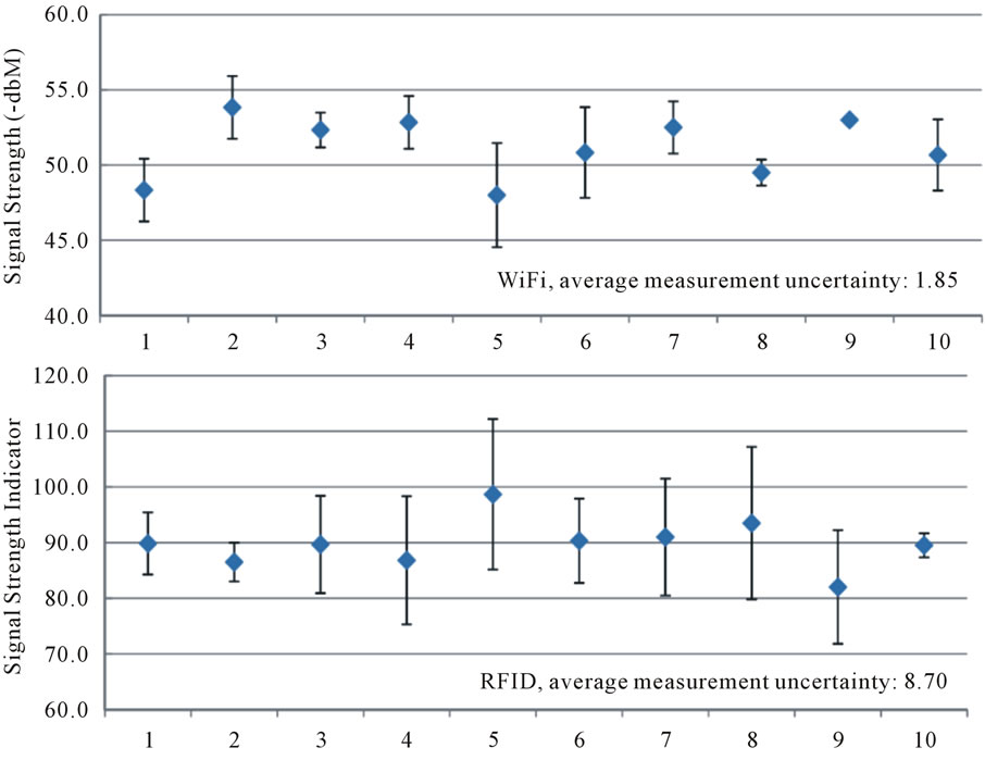
Figure 9. Signal strength measurements.
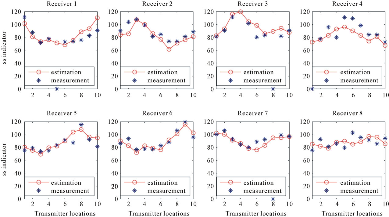
Figure 10. RFID SS measurements and estimations at all evaluation positions.

Table 1. Estimation errors when considering a floor as multiple walls.
signal strength estimation errors for these scenarios. The first column shows the possible number of walls for equivalent attenuation from a floor, and the 2nd and 3rd columns give the absolute and relative errors. The table shows that when the equivalent number of walls is 5, the model gives the best signal strength estimation, and thus it appears that the relative thickness between the floor and a wall plays a critical role, and the floor in the experimental building roughly counts for 5 walls in terms of WiFi radio attenuation.
Finally, we applied the new 3-D model (Equation (6)) for the whole building. We considered the floor separately using a distinct floor transmission coefficient. We received a very similar error result as the original model in the previous experimental evaluation. A point-by-point comparison chart between signal strength values from estimation (from the updated model) and actual measurement is given in Figure 11. We used a similar notation to that used in Figure 10, except that each receiver at a data evaluation position received radio signals from all 20 transmitters from both floors, and receivers from number 9 to 16 were located on the second floor. In this example, the updated model gave an average absolute error of 7.7696 and an average relative error of 10.14%, similar to (but slightly worse than) those for RFID (Figure 10) and to those using the original radio propagation model (Table 1). We believe that the structure of floor is very different from walls. As illustrated in Figure 12, the space between both floor surfaces is not filled with insulation materials; instead, the space could be used to plan for cables and various pipes (water, air conditioning, or vent). As a result, the structure of a floor is usually not uniformly distributed, and therefore radio attenuation (through floor) could be location dependent. This nonuniformness would potentially generate large errors by the radio propagation model since only one attenuation coefficient is considered for the floor, as indicated in Figures 10 and 11.
5. Discussion
Experiments indicated that the two radio propagation models in Equations (5) and (6) work remarkably well for the considered Science and Technology building, however, as readers can see from Figures 10, 11, and Table 1, minor errors still exist between estimations and measurements. We believe a simplified building structure could be one of the major reasons. As shown in Figure 6,

Figure 11. WiFi SS measurements and estimations at all evaluation positions.
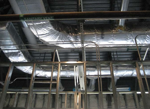
Figure 12. Typical structures inside a floor.
this research did not consider radio attenuation effects from furniture and other devices including computers, cable bundles, lab equipment, and medical instruments in the 2nd floor for the nursing program. Consequently, for future research, a fine-tuned building structure will have to be developed for precise estimation of radio signals inside the building.
The 3-D model (Equation (6)) delivered very similar results to those from original models (Equation (5)); however, the significant advantage of the new model is that it does not require a trial-and-error process in order to identify an equivalent number of walls that would generate similar radio attenuation from a floor. With the new model, it is intuitive (or extremely straight forward) to estimate radio signal strength values at any place in the building, allowing special focuses on interested locations or areas for certain mission critical applications.
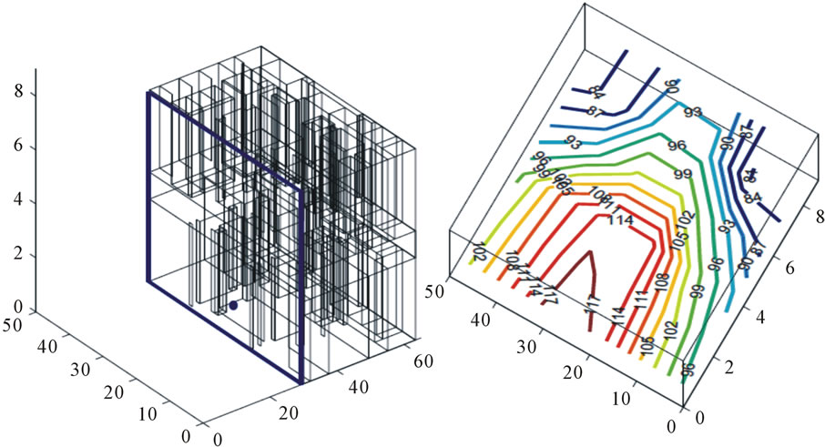
Figures 13 and 14 give two such examples of signal coverage in both horizontal and vertical planes in the Science and Technology building.
In Figure 13, x and y axes of both figures represent the building dimensions (in meters), and the z-axis shows the radio signal strength (signal strength indicator) at different measurement height. The left figure is a top-view of the signal strength distribution for positions on a horizontal plane 0.6 m above the floor; the right figure is a bottom-view diagram, and it gives signal strength distribution for positions on a horizontal plane 1.0 m above the floor. The signal strength distribution and the contour drawings from both figures in Figure 13 clearly indicate the changes of radio signal strength values in empty space (such as corridors) and across walls. It is clear that radio attenuation is not linearly distributed with distance from the transmitter. Comparing the two sub-figures, we see that signal strength values on the 1.0 m plane are slightly higher than corresponding positions on the 0.6 m
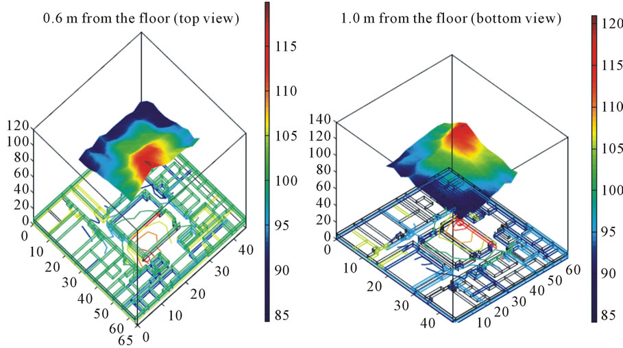
Figure 13. Signal estimation at horizontal planes of different heights from the floor.
 (a) (b)
Figure 14. Signal estimation at a vertical section of the building.
plane.
Figure 14 shows radio signal distribution along a vertical section plane from the building. The left figure gives the building section view as well as the location of a transmitter on the first floor. The right figure shows a distribution of radio signal strength along the vertical plane. As readers can see, signal strength values at locations on the first floor vary only in a very small range; however, as the radio propagates through the floor and to the second floor, its signal strength attenuates significantly. In the figure, it clearly shows a transitional change at the height between 4.0 meters and 6.0 meters, where signal strength values drop more than 15 units in just two meters because of the floor. For RFID radios, because of their lower frequency bands (and thus large wave length), the attenuation from the floor could be even severer and thus it explains the absence of most RFID signals across the floor in experiments in this research.
It is clear that the 3D radio propagation model is able to generate detailed radio signature in 3D space, and thus with detailed signal strength values across the building, many wireless applications could be deployed accordingly.
Since RFID devices used in this work could not transmit signals through the floor, we did not have a direct comparison evaluation study for the RFID radio (at 433.92 MHz) using the new model. But for the same floor, the evaluation study in Figure 10 did indicate that the original model does provide accurate estimation. We therefore conclude that the new model will also work well for the low frequency RFID radios (such as 433.92 MHz) if more powerful (or more sensitive) transmitters (tag) and receivers are used in the future.
6. Conclusion
In this research, we first demonstrated the essential impact of wall obstructions on indoor radio propagation by experimental results through a full cycle of an indoor construction process. We show that simple distancebased and wall obstruction based models would not be able to capture the nature of indoor radio propagation. We then proposed a practical 3-D indoor radio propagation model and evaluated radio propagation properties of both WiFi (at 2.4 GHz) and RFID (at 433 MHz) in a typical indoor environment. Using a two-story academic building consisting of classrooms and research labs, we conducted field measurements for both radio technologies utilizing the same configurations. We also estimated signal strength values for both radio technologies using the proposed model and we found that: 1) WiFi radio transmits at a larger range and is more stable than low frequency RFID technologies for indoor mobile computing; 2) compared with regular dry wall, floor partitions (or obstructions) significantly attenuate radio signals between neighboring floors, thus making radios at low frequency bands less effective, if not impossible, for multifloor3-D mobile applications; 3) radio signal attenuation from multiple partitions or obstructions is not linear, in fact, ray reflections from neighboring walls, ceiling, or floor may improve radio signal reception. Therefore simple distance-based radio propagation model does not work well indoors; similarly, models that consider obstruction attenuation as the multiplication of a single wall attenuation factor and the number of obstruction instances will also not work effectively in an indoor environment; 4) the proposed 3-D radio propagation model effectively and accurately estimates radio signal strength values at all data evaluation positions with similar small estimation errors for both RFID and WiFi radio technologies at 2.4 GHz and 433 MHz in this study. As a result we believe this research holds real potential for indoor wireless applications.
7. Acknowledgements
This project was supported by the Magellan Scholar Program of the University of South Carolina.
This material is based upon work supported by the National Science Foundation under Grants No. EPS- 0903795 and NO. CNS-0916012.
REFERENCES
- M. Weiser, “Ubiquitous Computing,” Xerox Palo Alto Research Center, 2012. http://sandbox.xerox.com/ubicomp/
- Weiser, Mark, “The Computer for the 21st Century,” Scientic American, 1991. http://www.ics.uci.edu/~dutt/ics212-wq05/weiser-sci-am-sep-91.pdf
- Insight Research Corp., “ Location Based Services Market, 2007-2011: A Market Research Report,” 2007. http://www.insightcorp.com/reports/ipappslbs.asp
- S. Dhar and U. Varshney, “Challenges and Business Models for Mobile Location-Based Services and Advertising,” Communications of the ACM, Vol. 54, No. 5, 2011, pp. 121-128. doi:10.1145/1941487. 1941515
- M. Satyanarayanan, “Mobile Computing: The Next Decade,” Proceedings of the 1st ACM Workshop on Mobile Cloud Computing & Services: Social Networks and Beyond, ACM, New York, 2010, pp. 5:1-5:6. doi:10.1145/1810931.1810936.
- Y. Ji, S. Biaz, S. Pandey and P. Agrawal, “ARIADNE: A Dynamic Indoor Signal Map Construction and Localization System,” The 4th International Conference on Mobile Systems, Applications, and Services, Uppsala, 19-22 June 2006.
- Y. Ji, S. Biaz, S. Wu and B. Qi, “Optimal Sniffers Deployment for Wireless Indoor Localization,” 16th International Conference on Computer Communications and Networks, Honolulu, 13-16 August 2007.
- Y. Ji, “Navigation Using Environmental Constraints,” 6th Annual IEEE Consumer Communications and Networking Conference, Las Vegas, 10-13 January 2009.
- Y. Ji and L. Chen, “Dynamic Indoor Location Determination: Mechanisms and Robustness Evaluation,” 6th International Conference on Autonomic and Autonomous Systems, Cancun, 7-13 March 2010, pp. 70-77.
- Y. Ji and P. Robert, “A 3-D Indoor Radio Propagation Model for WiFi and RFID,” 9th ACM International Symposium on Mobility Management and Wireless Access, Miami, 31 October-4 November 2011.
- Y. Ji, “Indoor Localization Robustness and Performance Improvement,” International Journal of Communication Networks and Distributed Systems: Special Issue on Scalable Wireless Networks, No. 1/2, 2011, pp. 3-15.
- Y. Ji, “Performance Analysis for Indoor Location Determination,” International Journal of Ad Hoc and Ubiquitous Computing: Special Issue on Wireless Network Algorithm and Theory, No. 1/2, 2011, pp. 3-15.
- R. Want, A. Hopper, V. Falcao and J. Gibbons, “The Active Badge Location Systems,” ACM Transactions on Information Systems, Vol. 10, No. 1, 1992, pp. 91-102.
- N. Priyantha, A. Chakraborty and H. Balakrishnan, “The Cricket Location Support System,” Proceedings of MOBICOM, Boston, 6-11 August 2000, pp. 266-274.
- A. Savvides, C.-C. Han and M. B. Strivastava, “Dynamic Fine-Grained Localization in Ad-Hoc Networks of Sensors,” MOBICOM, Rome, 16-21 July 2001.
- O. Vinyals, E. Martin and G. Friedland, “Multimodal Indoor Localization: An Audio-Wireless-Based Approach,” 4th International Conference on Semantic Computing, Pittsburgh, 22-24 September 2010, pp. 120-125.
- S. P. Tarzia, P. A. Dinda, R. P. Dick and G. Memik, “Demo: Indoor Localization without Infrastructure Using the Acoustic Background Spectrum,” Proceedings of the 9th International Conference on Mobile Systems, Applications, and Services, ACM, New York, 2011, pp. 385- 386. doi:10.1145/1999995.2000047.
- J. Krumm, S. Harris, B. Meyers, B. Brumitt, M. Hale and S. Shafer, “Multi-Camera Multi-Person Tracking for Easy Living,” 3rd IEEE International Workshop on Visual Surveillance, Dublin, 1 July 2000.
- M. Kais, S. Dauvillier, A. De la Fortelle, I. Masaki and C. Laugier, “Towards Outdoor Localization Using GIS, Vision System and Stochastic Error Propagation,” Palmerston North (NZ), 2004. http://emotion.inrialpes.fr/bibemotion/2004/KDDML04.
- M. Agrawal and K. Konolige, “Real-Time Localization in Outdoor Environments Using Stereo Vision and Inexpensive GPS,” Proceedings of the 18th International Conference on Pattern Recognition, IEEE Computer Society, Washington, 2006, pp. 1063-1068.
- N. Lemieux and H. Lutfiyya, “Whlocator: Hybrid Indoor Positioning System,” Proceedings of the 2009 International Conference on Pervasive Services, ACM, New York, 2009, pp. 55-64. doi:10.1145/1568199.1568209.
- O. Woodman and R. Harle, “Pedestrian Localisation for Indoor Environments,” Proceedings of the 10th International Conference on Ubiquitous Computing, ACM, New York, 2008, pp. 114-123. doi:10.1145/1409635.1409651.
- P. Robertson, M. Angermann and B. Krach, “Simultaneous Localization and Mapping for Pedestrians Using Only Foot-Mounted Inertial Sensors,” Proceedings of the 11th International Conference on Ubiquitous Computing, ACM, New York, 2009, pp. 93-96. doi:10.1145/ 1620545.1620560.
- P. Bahl and V. Padmanabhan, “RADAR: An In-Building RF-Based User Location and Tracking System,” Infocom, 2000, pp. 775-784.
- A. LaMarca, Y. Chawathe, S. Consolvo, J. Hightower, I. Smith, J. Scott, T. Sohn, J. Howard, J. Hughes, F. Potter, J. Tabert, P. Powledge, G. Borriello and B. Schilit, “Place Lab: Device Positioning Using Radio Beacons in the Wild,” Proceedings of Pervasive, Munich, 8-13 May 2005, pp. 116-133.
- Y.-C. Cheng, Y. Chawathe, A. LaMarca and J. Krumm, “Accuracy Characterization for Metropolitan-Scale Wi-Fi Localization,” Mobisys, 2005.
- S. Tadakamadla, “Indoor Local Positioning System for Zigbee, Based on RSSI,” Master’s Thesis, Mid Sweden University, Östersund, 2006.
- J. Blumenthal, R. Grossmann, F. Golatowski and D. Timmermann, “Weighted Centroid Localization in ZigBee-Based Sensor Networks,” IEEE International Symposium on Intelligent Signal Processing, Alcala De Henares, 3-5 October 2007, pp. 1-6.
- A.-I. Noh, W. Lee and J. Ye, “Comparison of the Mechanisms of the ZigBee’s Indoor Localization Algorithm,” 9th ACIS International Conference on Software Engineering, Artificial Intelligence, Networking, and Parallel/Distributed Computing, Kyoto, 6-8 August 2008, pp. 13-18.
- K. Curran and E. Furey, “Pinpointing Users with Location Estimation Techniques and Wi-Fi Hotspot Technology,” International Journal of Network Management, Vol. 18, No. 5, 2008, pp. 395-408. doi:10.1002/nem.683.
- Y.-S. Chiou, C.-L. Wang, S.-C. Yeh and M.-Y. Su, “Design of An Adaptive Positioning System Based on Wi-Fi Radio Signals,” Computer Communications, Vol. 32, No. 7-10, 2009, pp. 1245-1254. http://portal.acm.org/citation.cfm?id=1542555.1542776.
- K. Chintalapudi, A. PadmanabhaIyer and V. N. Padmanabhan, “Indoor Localization without the Pain,” Proceedings of the 16th Annual International Conference on Mobile Computing and Networking, ACM, New York, 2010, pp. 173-184. doi:10.1145/ 1859995.1860016.
- M. Giuberti, M. Martalo and G. Ferrari, “Fingerprinting-Based Wireless 3d Localization for Motion Capture Applications,” Proceedings of the 1st ACM Mobi Hoc Workshop on Pervasive Wireless Healthcare, ACM, New York, 2011, pp. 6:1-6:8. doi:10.1145/ 2007036.2007044.
- R. Russell, “A Practical Demonstration of the Application of Olfactory Sensing to Robot Navigation,” Proceedings of the International Advanced Robotics Program, Sydney, 18-19 May 1995, pp. 35-43.
- S. K. Yeluri, “Outdoor Localization Technique Using Landmarks to Determine. Position and Orientation,” Master’s Thesis, University of Florida, Gainesville, 2003.
- L. E. Miller, P. F. Wilson, N. P. Bryner, M. H. Francis, J. R. Guerrieri, D. W. Stroup and L. Klein-Berndt, “RfidAssisted Indoor Localization and Communication for First Responders,” The European Conference on Antennas and Propagation, Nice, 6-10 October 2006.
- J. Borkowski and U. Lempiainen, “Practical NetworkBased Techniques for Mobile Positioning in Umts,” EURASIP Journal on Applied Signal Processing, 2006, pp. 1-15, Article ID 12930.
- A. Kealy, G. Roberts and G. Retscher, “Evaluating the Performance of Low Cost Mems Inertial Sensors for Seamless Indoor/Outdoor Navigation,” Position Location and Navigation Symposium, Indian Wells, 4-6 May 2010, pp. 157-167.
- M. Isaac, “New Version of Google Maps Brings Indoor Floor Plans to Your Phone,” CNN Tech, 2011. http://www.cnn.com/2011/11/30/tech/mobile/new-version-googlemaps-indoors-wired/.
- J. Hightower and G. Boriello, “Localization Systems for Ubiquitous Computing,” IEEE Computer Magazine, Vol. 34, No. 8, 2001, pp. 57-66.
- S. Thrun, “Robotic Mapping: A Survey,” 2002. http://citeseer.ist.psu.edu/thrun02robotic.html.
- R. J. Fontana, E. Richley and J. Barney, “Commercialization of an Ultra-Wideband Precision Asset Location System,” IEEE Conference on Ultra-Wideband Systems and Technologies, Reston, 16-19 November 2003, pp. 369- 373.
- E. Elnahrawy, X. Li and R. P. Martin, “The Limits of Localization Using Signal Strength: A Comparative Study,” Sensor Systems, Baltimore, 3-5 November 2004, pp. 283-284.
- X. Cheng, A. Thaeler, G. Xue and D. Chen, “TPS: A Time-Based Positioning Scheme for Outdoor Sensor Networks,” IEEE Infocom, Vol. 4, 2004, pp. 2685-2696.
- A. H. Sayed, A. Tarighat and N. Khajehnouri, “Network-Based Wireless Location: Challenges Faced in Developing Techniques for Accurate Wireless Location Information,” IEEE Signal Processing Magazine, Vol. 22, No. 4, 2005, pp. 24-40.
- M. Youssef, A. Youssef, C. Rieger, U. Shankar and A. Agrawala, “Pinpoint: An Asynchronous Time-Based Location Determination System,” MobiSys 2006, ACM Press, New York, 2006, pp. 165-176.
- H. Lim, L. Kung, R. Doverspike and J. Hou, “Zero-Config., Robust Indoor Localization: Theory and Experimentation,” InfoCom, 2006.
- A. Aksu and P. Krishnamurthy, “Sub-Area Localization: A Simple Calibration Free Approach,” Proceedings of the 13th ACM International Conference on Modeling, Analysis, and Simulation of Wireless and Mobile Systems, ACM, New York, 2010, pp. 63-72. doi:10.1145/ 1868521.1868534.
- M. Kallmann, “Shortest Paths with Arbitrary Clearance from Navigation Meshes,” Proceedings of the 2010 ACM SIGGRAPH/Eurographics Symposium on Computer Animation, Eurographics Association, Aire-la-Ville, 2010, pp. 159-168. http://dl.acm.org/citation.cfm? id=1921427.1921451
- K. Lin, A. Kansal, D. Lymberopoulos and F. Zhao, “Energy-Accuracy Trade-Off for Continuous Mobile Device Location,” Proceedings of the 8th International Conference on Mobile Systems, Applications, and Services, ACM, New York, 2010, pp. 285-298. doi:10.1145/ 1814433.1814462.
- H. Lim, L.-C. Kung, J. C. Hou and H. Luo, “Zero-Configuration Indoor Localization over IEEE 802.11 Wireless Infrastructure,” Wireless Networks, Vol. 16, 2010, pp. 405-420. doi:10.1007/s11276-008-0140-3.
- A. M. Ladd, K. E. Bekris, A. P. Rudys, D. S. Wallach and L. E. Kavraki, “On the Feasibility of Using Wireless Ethernet for Indoor Localization,” IEEE Transactions on Robotics and Automation, Vol. 20, No. 3, 2004, pp. 555- 559.
- P. Krishnan, A. Krishnakumar, W. Ju, C. Mallows and S. Ganu, “A Systemfor LEASE: System for Location Estimation Assisted by Stationary Emitters for Indoor Wireless Networks,” Infocom, 2004.
- Skyhook Wireless, 2012. http://www.skyhookwireless.com/
- A. Haeberlen, E. Flannery, A. M. Ladd, A. Rudys, D. S. Wallach and L. E.Kavraki, “Practical Robust Localization over Large-Scale 802.11 Wireless Networks,” MobiCom, Philadelphia, 2004.
- A. Hatami and K. Pahlavan, “In Building Intruder Detection for WLAN Access,” Position Location and Navigation Symposium, Monterey, 26-29 April 2004, pp. 592- 597.
- M. Chen, T. Sohn, J. Hightower, T. Sohn, A. LaMarca, I. Smith, D. Chmelev, J. Hughes and F. Potter, “Practical Metropolitan-Scale Positioning for GSM Phones,” Proceedings of Ubicomp, Orange County, 17-21 September 2006.
- Y.-S. Chiou, C.-L. Wang and S.-C. Yeh, “An Adaptive Location Estimator Using Tracking Algorithms for Indoor WLANS,” Wireless Networks, Vol. 16, 2010, pp. 1987-2012. doi:10.1007/ s11276-010-0240-8.
- G. P. Roston and E. Krotkov, “Dead Reckoning Navigation for Walking Robots,” Robotics Institute, Carnegie Mellon University, Pittsburgh, 1991.
- [61] J. Craig, “Introduction to Robotics, Mechanics and Control,” Addison-Wesley, New York, 1986.
- [62] N. Satthamnuwong, “Dead Reckoning-Aided GPS Vehicle Navigation Using Sequential Least Squares with Weighted Constraints,” Ph.D. Dissertation, Purdue University, West Lafayette, 2002.
- [63] D. Gebre-Egziabher, J. D. Powell, and P. Enge, “Design and Performance Analysis of a Low-Cost Aided Dead Reckoning Navigation System,” International Conference on Integrated Navigation Systems, St. Petersburg, 28-30 May 2001.
- [64] N. A. Alsindi, “Performance of Toa Estimation Algorithms in Different Indoor Multipath Conditions,” Master’s Thesis, Worcester Polytechnic Institute, 2004.
- [65] T. S. Rappaport, “Wireless Communications: Principles and Practice,” 2nd Edition, Prentice Hall, Upper Saddle River, 2001.
- [66] M. Lott and I. Forkel, “A Multi-Wall-and-Floor Model for Indoor Radio Propagation,” Vehicular Technology Conference, Vol. 1, 2001, pp. 464-468.
- [67] S. Phaiboon, “An Empirically Based Path Loss Model for Indoor Wireless Channels in Laboratory Building,” IEEE TENCON, Vol. 2, 2002, pp. 1020-1023.
- [68] M. Hassan-Ali and K. Pahlavan, “A New Statistical Model for Site-Specific Indoor Radio Propagation Prediction Based on Geometric Optics and Geometric Probability,” IEEE Transactions on Wireless Communications, Vol. 1, 2002, pp. 112-124.
- [69] A. Hills, J. Schlegel and B. Jenkins, “Estimating Signal Strengths in the Design of an Indoor Wireless Network,” IEEE Transactions on Wireless Communications, Vol. 3, No. 1, 2004, pp. 17-19.
- [70] A. M. Hossain, H. N. Van, Y. Jin and W.-S. Soh, “Indoor Localization Using Multiple Wireless Technologies,” IEEE Mobile Ad Hoc and Sensor Systems, Pisa, 8-11 October 2007, pp. 1-8.
- [71] Y. Ji, “Ultimate Precision Bound and Comparison Study of Dynamic Indoor Localization Systems,” Wireless Conference (EW), Lucca, 12-15 April 2010, pp. 149-156.
- [72] W. S. Holland, “Development of an Indoor Real-Time Localization System Using Passive rfid Tags and Artificial Neural Networks,” Master’s Thesis, Ohio University, Athens, 2009.
- [73] G. Y. Jin, X. Y. Lu and M.-S. Park, “An Indoor Localization Mechanism Using Active Rfid Tag,” International Conference on Sensor Networks, Ubiquitous, and Trustworthy Computing, Vol. 1, 2006, pp. 40-43.
- [74] K. Curran and S. Norrby, “Rfid-Enabled Location Determination within Indoor Environments,” International Journal of Ambient Computing and Intelligence, Vol. 1, No. 4, 2009, pp. 63-86.
- [75] E. Welbourne, K. Koscher, E. Soroush, M. Balazinska and G. Borriello, “Longitudinal Study of a Building-Scale Rfid Ecosystem,” Proceedings of the 7th International Conference on Mobile Systems, Applications, and Services, ACM, New York, 2009, pp. 69-82. doi:10.1145/ 1555816.1555824.
- [76] T. Li, S. Chen and Y. Ling, “Identifying the Missing Tags in a Large RFID System,” Proceedings of the 11th ACM International Symposium on Mobile Ad Hoc Networking and Computing, ACM, New York, 2010, pp. 1-10. doi:10.1145/1860093.1860095.
- [77] C. Wang, B. Li, M. Daneshmand, K. Sohraby and R. Jana, “On Object Identification Reliability Using RFID,” Mobile Networks and Applications, Vol. 16, 2011, pp. 71-80. doi:10.1007/s11036 -010-0226-x.
- [78] T. Kuflik, O. Stock, M. Zancanaro, A. Gorfinkel, S. Jbara, S. Kats, J. Sheidin and N. Kashtan, “A Visitor’s Guide in an Active Museum: Presentations, Communications, and Reflection,” Journal on Computing and Cultural Heritage, Vol. 3, 2011, pp. 11:1-11:25. doi:10.1145/1921614.1921618.
- [79] R. A. Valenzuela, O. Landron, and D. L. Jacobs, “Estimating Local Mean Signal Strength of Indoor Multipath Propagation,” Vehicular Technology Conference, Vol. 46, No. 1, 1997, pp. 203-212.
- [80] P. Ali-Rantala, L. Sydanheimo, M. Keskilammi and M. Kivikoski, “Indoor Propagation Comparison between 2.45 GHz and 433 MHz Transmissions,” Antennas and Propagation Society International Symposium, Vol. 1, 2002, pp. 240-243.
- [81] Y. Alvarez, M. E. de Cos, J. Lorenzo and F. Las-Heras, “Novel Received Signal Strength-Based Indoor Location System: Development and Testing,” EURASIP Journal on Wireless Communications and Networking, Vol. 2010, 2010, pp. 1-11. doi:10.1155/ 2010/254345.
- [82] R. A. Valenzuela, “Ray Tracing Prediction of Indoor Radio Propagation,” Wireless Networks—Catching the Mobile Future, 5th IEEE International Symposium on Personal, Indoor and Mobile Radio Communications, AT&T Bell Laboratories, Crawford Hill Laboratory, Holmdel, 18-23 September 1994.
- [83] C.-F. Yang, B.-C. Wu and C.-J. Ko, “A Ray-Tracing Method for Modeling Indoor Wave Propagation and Penetration,” IEEE Transaction on Antennas and Propagation, Vol. 46, No. 6, 1998.
- [84] K. Remley, H. Anderson and A. Weisshar, “Improving the Accuracy of Ray Tracing Techniques for Indoor Propagation Modeling,” IEEE Transactions on Vehicular Technology, Vol. 49, No. 6, 2000, pp. 2350-2358.
- [85] H. Weghorst, G. Hooper and D. P. Greenberg, “Improved Computational Methods for Ray Tracing,” ACM Transactions on Graphics, Vol. 3, No. 1, 1984, pp. 52-69. doi:10.1145/357332.357335.
- [86] F. A. Agelet, F. P. Fontan and A. Formella, “Fast Ray Tracing for Microcellular and Indoor Environments,” IEEE Transactions on Magnetics, Vol. 33, No. 2, 1997, pp. 1484-1487.
- [87] Z. Ji, B.-H. Li, H.-X. Wang, H.-Y. Chen and T. K. Sarkar, “Efficient Ray-Tracing Methods for Propagation Prediction for Indoor Wireless Communications,” IEEE Antennas and Propatation Magazine, Vol. 43, No. 2, 2001, pp. 41-49.
- [88] C. Oestges and A. Paulraj, “Propagation into Buildings for Broad-Band Wireless Access,” IEEE Transactions on Vehicular Technology, Vol. 53, No. 2, 2004, pp. 521- 526.
- [89] Y. Ji, S. biaz, S. Wu and B. Qi, “Impact of Building Environment on the Performance of Dynamic Indoor Localization,” 8th Annual IEEE Wireless and Microwave Technology Conference, Clearwater, 4-5 December 2006.
- [90] WaveTrend, “Wave Trend Personal Tag tg501,” 2012. http://www.wavetrend.net/downloads/information-sheets/TG501-0API-A4.pdf.
NOTES
1RFID may also use WiFi technology [71], in this research, we refer to RFID as a technology that uses lower frequency bands at 433 MHz or 868 - 928 MHz.

