Int'l J. of Communications, Network and System Sciences
Vol. 5 No. 7 (2012) , Article ID: 21335 , 6 pages DOI:10.4236/ijcns.2012.57053
Semi-Blind Reception Using Joint Channel Estimation in IDMA Systems
1LCPTS Laboratoire de Communication et du Traitement du Signal, FEI-USTHB, Alger, Algérie
2CNRS, LAAS, 7 avenue du Colonel Roche, Toulouse, France
3Univ. de Toulouse, LAAS, Toulouse, France
Email: ahamza@usthb.dz
Received March 26, 2012; revised May 7, 2012; accepted May 17, 2012
Keywords: Channel Estimation; IDMA; Multiuser Detection
ABSTRACT
In this paper a bi-directional system based on linear channel estimation and data detection using turbo detection algorithm is proposed. By combining channel estimation with an iterative chip-by-chip detection process (inner loop) in an iterative way (outer loop), communications performance can be further increased. We present results on blind reception in case of Interleave Division Multiple Access (IDMA) system when the channel coefficients are unknown. We develop a low-complexity iterative joint channel/code estimation method. The philosophy of the turbo processing is the iterative exchange of related information which yields a substantial improvement of the overall system performance. We analyze the achievable performance of the iterative system proposed. Simulation results demonstrate the efficiency of the proposed algorithms.
1. Introduction
The present paper proposes a semi-blind channel estimation method, based on conditional Gaussian particle algorithm for IDMA systems, to track varying channel coefficients. The performance of Code Division Multiple Access (CDMA) systems is mainly limited by Multiple Access Interference (MAI) and Inter Symbol Interference (ISI). Chip-level interleavers for user separation can separate different users without spreading within the CDMA framework. An interleaver based multiple access scheme has also been studied in [1,2] for high spectral efficiency, improved error performance and low receiver complexity. This paper concerns transmission and detection principles using interleavers as the only means for user separation, incorporating principles developed in [3,4]. Interleave Division Multiple-Access (IDMA) systems communication is one of the most promising technologies for high data rate wireless networks. IDMA inherits many advantages from CDMA, in particular, diversity against fading and mitigation of the worst-case other-cell user interference problem. Furthermore, IDMA allows a very simple chip-by-chip iterative Multi User Detection (MUD) strategy [5]. The normalized MUD cost (per user) can be made independent of the user number. From the receiver point of view the unknown channel degrades the accuracy of symbol detection. This can be eliminated using estimation methods on Channel State Information (CSI). Channel coefficient estimation is usually performed using known training sequences which are periodically transmitted (for instance, at the start of each frame), implicitly assuming that the channel does not vary between two training sequences. An iterative procedure to track the channel variations by refining the channel coefficients in a semi-blind manner is proposed. The paper is organized as follows: section 2 introduces the IDMA system and settles the various notations. Section 3 recalls the Chip by Chip (CBC) algorithm and its application on IDMA system, as well as channel estimation. This section presents also, the new detection system based on semi-blind channel estimation. Finally, section 4 illustrates the performance of the proposed algorithm through simulation results. Section 5 concludes the paper.
2. IDMA System Model
IDMA Transmitter and Receiver Structures are shown in
Figure 1 for the multiple access scheme under consideration with K simultaneous users, with perfect channel knowledge. The input data sequence dk of user-k is spread by a length C spreading sequence, generating a coded sequence ck = [ck(1); …; ck(j); …; ck(J)]T , where J is the frame length. The elements in ck are referred to as coded bits. Then ck is permuted by an interleaver π(k), producing the vector xk = [xk(1); …; xk(j); …; xk(J)]T. We
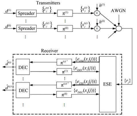
Figure 1. The transmitter and turbo receiver. π and π–1 denote interleaver and deinterleaver, respectively.
call the elements in xk chips. Users are distinguished by their interleavers, hence the name Interleave Division Multiple Access (IDMA). The key principle of IDMA is that the interleavers π(k) should be different for different users. We assume that they are generated independently and randomly. These interleavers disperse the coded sequences so that the adjacent chips are approximately uncorrelated, which facilitates the simple chip-by-chip detection scheme [6]. Classical IDMA communication system is adopted as illustrated in Figure 1, which consists of an elementary signal estimator (ESE) and K singleuser a posteriori probability (APP) decoders (DECs). In our cases (DECs) are formed by despreaders.
The outputs of the ESE and DECs are extrinsic loglikelihood ratios (LLRs) about xk(j) defined below as:
 (1)
(1)
These a posteriori LLRs are further distinguished as eESE(xk(j)) and eDEC(xk(j)), depending on whether they are generated by the ESE or DECs and channel coefficient hk(j). A global turbo-type iterative process is then applied to process the LLRs, as detailed in [7]. The information bits for user k are first spread, then interleaved and transmitted over a channel. The received signal can be written as:
 (2)
(2)
where  is the jth chip transmitted by user k, hk(j) the time-varying coefficient for user k and n(j) are samples of an Additive White Gaussian Noise (AWGN) process with zero-mean and variance
  = N0/2. When we assume quasi-static single-path channels, the coefficients hk(j) of the channel are known from the receiver. In this case, the bit detection can be done by an ESE operation carried out a chip-by-chip manner. From (2) we define:
 (3)
(3)
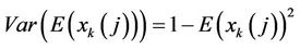
where  is the distortion including interference plus noise in r(j) with respect to user-k. The mean and the variance functions are noted by E(.) and Var(.) respectively.
  can be approximated by a random Gaussian variable. A detailed derivation of the detection algorithm is given in [7,8]. Here we only list the algorithm:
1) Initialization set
 (4)
(4)
2) Main operations


3) LLR generation
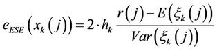 (5)
(5)
It can be verified that the above algorithm is an extremely simplified method. The cost per information bit per user increases linearly with the spreading length but is independent of the number of users K.
3. Joint Channel/Symbol Estimation
The classical iterative chip by chip algorithm is based on the assumption that the receiver has ideal channel state information (CSI). We now proceed to consider the channel estimation issue.
3.1. Channel Estimation
We investigate recursive estimation for IDMA systems without assuming channel knowledge over time-varying and quasi-static channels. The received signal, given by Equation (2) can be written as:
r(j) = hk(j)∙xk(j) +  (6)
(6)
so the channel response at time j + 1 is done by:
hk(j + 1) = hk(j) + wk(j + 1)  j;
j;  k(7)
k(7)
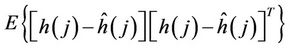
where hk(j) is the state channel (the single path situationconsidered here is, of course, easily extended to multipath, via straightforward state-augmentation), wk(j) is the zero mean, white Gaussian noise with covariance , and the noise covariance matrix Q(j) of the vector noise w(j) = [w1(j), …, wK(j)]. We assume that there is no inter-block interference. This allows independent processing of blocks. Let
  be the filtered state vector and P(j) be the (N × N) corresponding filtered error variance, where
  is the filtered error covariance matrix defined as
 .
.
When a pilot embedding technique is used both with iterative joint channel estimation and multi-user detection [9,10], the transmitted signal from user k is the superposition of the data signal xk and pilot pk, where SA is the pilot length.
The received signals for pilot symbols at known locations, pk = {pk(l), pk(z), …, pk(SA)} is the pilot for user k.
Assuming that pk are randomly and independently generated the initial estimate for our iterative algorithm is obtained using possible pilot symbols and deterministic estimator.
For pilot symbols, channel coefficients can be estimated in the usual linear Gaussian framework:
1) Step 1: Initialisation
{h(0/–1); P(0/–1) (initial mean, covariance)}.
2) Step 2: Prediction Prediction process for the filter is obtained using the evaluation equations of the mixed state vector 
The error covariance prediction is given by:
 (8)
(8)
3) Step 3: Filtering The states predicted by dynamic filters conditionally to j are updated using Kalman filter equations given by:
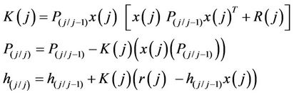 (9)
(9)
Where K(j) is the Kalman gain.
3.2. Combined Estimation, Detection and Decoding
The following is a brief outline of the function of each module in the iterative process. The lower part of Figure 1 shows the receiver structure under the assumption of known parameters of the channel hk(j).
As channel variables are to be jointly estimated, we shall assume that channel is either static or slowly time-varying within a frame.
3.2.1. Pilot Symbols Processing
Pilot signals can be performed for finer estimation, during the inner decoder iterations and outer estimator/ decoder iterations.
1) time Varying Channel It requires computation of corrected channel coefficients for each chip . However, this is possible, after some iterative decoding system (local). In the following, we give the details of the detection system which iterates via the three modules.
a) Based on the pilot sequences and the a priori statistics of the time-varying channel; the channel estimator . j = 1, …, SA is updated as in A and hk(j) will be equal to
  the last value estimated by the training pilot:
 (10)
(10)
b) Based on the estimation of hk(j) from the channel estimates, the IDMA system computes the extrinsic LLRs for x(j).
c) Based on the pilot symbols, and the estimation of symbols xk(j), the channel estimator refines the data estimates { , k = 1, …, K and j = 1, …, J}.
For the next iteration, an estimate of the transmitted symbols and of the channel coefficient is used. A new estimated coefficient is calculated after full decoder/ estimator iterations. For the Nth iteration of the decoder, the LLR values of the transmitted bits are calculated on the base of the (L-1)th iterated estimate ; Where N = M × L, M is the number of estimation iterations, L the number of decoder iterations for each channel estimation. In order to reduce algorithmic complexity we use the ratio 1:5 between the number of inner iteration M and outer iteration L.
2) Static Channel We focus on the static channel case where the coefficients are assumed to be constant over the whole frame. This can be considered as a special case of the above general model. For this case, data matrix  [K; J] reduces to a vector whose coefficient are simply given as
  and Qj = 0 in Equation (8).
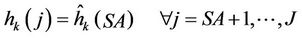
We assume, here, that the estimator  is the last filtered value hSA/SA and there is no change. But, of course, this estimator is valid only when we use a pilot sequence for estimating the vector channel coefficients. Otherwise iterative estimation is used instead.
3.2.2. Blind Case
In this case there is no bit information available for the iterative joint process discussed. According to the discussion above, we need to set up values hk(j) that are updated, based on the feedbacks from the decoder in the iterative process. In the first iteration, we use the a priori information E(hk(j))  j; k.
j; k.
There are always decoder feedbacks available, and the channel coefficients are considered slowly varying during the time interval. Then the feedbacks from the decoder after the M next iterative decoding processes will be used in the next coefficient estimation.
The method of joint iterative turbo decoding and estimation is called turbo detection. Turbo detection allows decreasing the number of pilot symbols for estimation purposes and thus increases the user data rate for a given bandwidth. This method can be used to detect the symbols blindly. Such an iterative algorithm is shown in Figure 2.
4. Simulation Results
4.1. Static Channel
These results have been obtained with spreading codes length C = 8, K = 8 users, J = 2048 chips. Let us first test the effect of the estimation block on the receiver system. In Figure 3, we compare the performance of the IDMA algorithm, with different random values of hk(j) for k = 1, …, K; j = 1, …, J; in two different cases:
• Without estimation block: the coefficients of the channel are fixed as hk(j) = 1  k, j at the receiver and the algorithm in section 2 is applied.
• With blind estimation: the channel coefficients are blindly estimated, with three estimation iterations.
The Figure 3 illustrates the mean Bit Error Rate (BER) versus signal-to noise ratio (SNR = Eb = N0), where Eb is the mean user bit signal power.
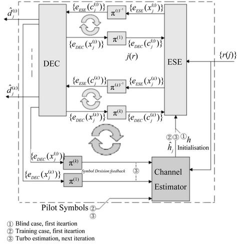
Figure 2. Turbo Decoder with fine estimation.

Figure 3. BER versus SNR performance exhibited by the iterative turbo receiver without and with blind channel estimation.
4.2. Time-Varying Channel
Figure 4 shows the performance of the proposed iterative algorithm in time varying channels when  = 0.001 (i.e. while subject to a random walk of ±25% over the whole frame) and give a comparison with the detection under perfect CSI at receiver side, for J = 256 × 8 chips and the performance exhibited by the iterative turbo receiver of Figure 2.
We illustrate, in Figure 5 the performance of the system under the same simulation conditions with  = 0, 01. In Figure 6, the evolution of the BER for variable standard deviation from
  = 0.0001 to
  = 0.1 is illustrated, in the same simulation conditions than above. We observe good performance for
  = 0.0001 until
  = 0.001, and poor performance for
  > 0.01.
4.3. Trajectory Channel Variation
Figures 7 and 8 illustrate the evolution of estimated channel coefficients using the iterative algorithm with five pilot sequences (SA = 5) and without any pilot sequence, respectively and also provide the exact trajectory of coefficient h4
5. Conclusion
In this paper we proposed low complexity iterative joint channel estimation, and decoding scheme for IDMA systems. This method has been developed to extract all the data/channel information through a two-level iteration algorithm. The proposed system inherits the low-complexity advantage of IDMA technique. In this paper, we have documented the performance trends exhibited by the proposed turbo detection receiver. The results obtained

Figure 4. BER versus SNR for channel time-varying with SA = 5 and σw = 0.001. For M = 5 (decoding iterations) and L = 0; 1; 2; 3 (channel estimation iteration).

Figure 5. BER versus SNR for channel time-varying with SA = 5 and σw = 0.01. For M = 5 (decoding iterations) and L = 0; 1; 2; 3 (channel estimation iteration).

Figure 6. The BER versus SNR performance exhibited by turbo detection. The pilot bits with SA = 5 and the iteration pattern (M; L; N) = (5; 3; 15).

Figure 7. Sample trajectory of h4 at SNR = 5 dB, σw = 0:01 with channel estimation (SA = 5 bits).

Figure 8. Sample trajectory of h4 at SNR = 5 dB, σw = 0:01 with blind channel estimation.
show the efficacy of such methods even in blind case when the channel is unknown. Furthermore, we note that other techniques such as the Particle Filter method can be used to improve its effectiveness further.
REFERENCES
- A. D. Damnjanovic and B. R. Vojcic, “Iterative MuliUser Detection/Decoding for Turbo Coded CDMA Systems,” IEEE Communications Letters, vol. 5, No. 3, 2001, pp. 104-106. doi:10.1109/4234.913154
- X. Wang and H. V. Poor, “Iterative (Turbo) Soft Interference Cancellation and Decoding for Coded CDMA,” IEEE Transactions on Communications, vol. 47, No. 7, 1999, pp. 1046-1061. doi:10.1109/26.774855
- S. Brck, U. Sorger, S. Gligorevic and N. Stolte, “Interleaving for Outer Convolutional Codes in DS-CDMA Systems,” IEEE Transactions on Communications, vol. 48, No. 7, 2000, pp. 1100-1107. doi:10.1109/26.855517
- R. H. Mahadevappa and J. G. Proakis, “Mitigating Multiple Access Interference and Intersymbol Interference in Uncoded CDMA Systems with Chip-Level Interleaving,” IEEE Transactions on Wireless Communications, vol. 1, No. 4, 2002, pp. 781-792. doi:10.1109/TWC.2002.804163
- C. Berrou and A. Glavieux, “Near Shannon Limit Error Correcting Coding and Decoding: Turbo-Codes,” IEEE Transactions on Communications, vol. 44, No. 10, 1996, pp. 1261-1271. doi:10.1109/26.539767
- P. Li, L. h. Liu, K. y. Wu and W. K. Leung, “Interleave Division Multiple-Access,” IEEE Transactions on Wireless Communications, Vol. 5, No. 4, 2006, pp. 938-947.
- P. Li, “Interleave-Division Multiple Access and Chipby-Chip Iterative Multi-User Detection,” IEEE Communications Magazine, Vol. 43, No. 6, 2005, pp. S19-S23. doi:10.1109/MCOM.2005.1452830
- H. Abdelkrim, et al., “Independent Component Analysis in IDMA Systems,” Circuits and Systems and TAISA Conference, Toulouse, 28 June-1 July 2009, pp. 1-4.
- M. Moher and P. Guinand, “An Iterative Algorithm for Asynchronous Coded Multi-User Detection,” IEEE Communications Letters, vol. 2, No. 8, 1998, pp. 229-231. doi:10.1109/4234.709440
- A. Kazem, G. Salut and F. Lehmann, “Iterative Joint Phase/Timing Estimation and Decoding for GEO Satellite Links in the Presence of Doppler Shift,” Proceedings of the Eighth International Symposium on Signal Processing and Its Applications, Sydney, 28-31 August 2005, pp. 271-274.