Int'l J. of Communications, Network and System Sciences
Vol. 5 No. 4 (2012) , Article ID: 18523 , 10 pages DOI:10.4236/ijcns.2012.54030
E2E KEEP: End to End Key Exchange and Encryption Protocol for Accelerated Satellite Networks
1Informatics Services Corporation, Tehran, Iran
2Electrical Engineering Department, Amirkabir University of Technology, Tehran, Iran
Email: {h_fereidooni, m_mahramian}@isc.iranet.net, htaheri@aut.ac.ir
Received February 12, 2012; revised March 12, 2012; accepted March 27, 2012
Keywords: Virtual Private Networks (VPNs); Public Key Infrastructure; Authentication; Internet key exchange (IKE); BAN-logic
ABSTRACT
Accelerating methods are used to enhance TCP performance over satellite links by employing Performance Enhancement Proxies (PEPs). However, providing a secure connection through the PEPs seems to be impossible. In this paper an appropriate method is proposed in order to provide an accelerated secure E2E connection. We show an efficient secure three-party protocol, based on public key infrastructure (PKI), which provides security against spiteful adversaries. Our construction is based on applying asymmetric cryptography techniques to the original IKE protocol. Security protocols use cryptography to set up private communication channels on an insecure network. Many protocols contain flaws, and because security goals are seldom specified in detail, we cannot be certain what constitute a flaw. Proofing security properties is essential for the development of secure protocol. We give a logic analysis of the proposed protocol with the BAN-logic and discuss the security of the protocol. The result indicates that the protocol is correct and satisfies the security requirements of Internet key exchange. Based on the results of this preliminary analysis, we have implemented a prototype of our security protocol and evaluated its performance and checked safety properties of security protocol, and the results show that the protocol is robust and safe against major security threats.
1. Introduction
Virtual Private Networks (VPNs) provide the user with secure duplex connection channels [1]. As a privacy protecting measure, VPNs are employed to encapsulate TCP/IP stream and safeguard it against interference, snooping, hijack or attack. In essence, a VPN provides a secured “tunnel” between two end points across a public network. The protocols used over the Internet (TCP/IP) are designed for reliable end-to-end data delivery over unreliable and congested networks. In a satellite connection the circuit is not congested in the same way that a terrestrial connection might be; there is less retransmission and recovery. However, satellite bears a high latency (delay) medium and TCP response to such latency is not in a determined way. To begin a data transmission, TCP uses a slow-start mechanism to determine any present congestion on the network. A delay over satellite link is interpreted as congestion; therefore the slow start mechanism remains in force for the duration of the transmission. Combined with the need to make frequent acknowledgments for the receipt and transmission of each packet this leads to a very inefficient use of a medium that is inherently reliable and uncontested. As a remedy treatment for limitations of TCP over satellite, the equipment and service providers pass TCP and other application layer protocols through Performance Enhancing Proxies (PEP) which accelerate this traffic over the satellite connection. The PEP applies a number of methods such as window size reduction for packet transmission and selectively omitting some acknowledgment requirements in data stream. VPN tunnels encrypt user information at both ends to ensure secrecy and authentication. Therefore, sender and receiver sides, before any data transfer, need to exchange encryption keys. When an IPSec VPN is used, the TCP headers encapsulated within the VPN data stream cannot be accelerated. There are some techniques to set up an accelerated secure VPN over satellite links [2]:
• Trusted PEPs (see Figure 1);
• Application layer Security Protocols;
• changing IPSec to make the header accessible;
• Multilayer security (ML-IPSec).
Each packet will be divided into different sections by ML-IPsec and encrypted independently [3]. In this method, PEPs have only header encryption key, thereby they do
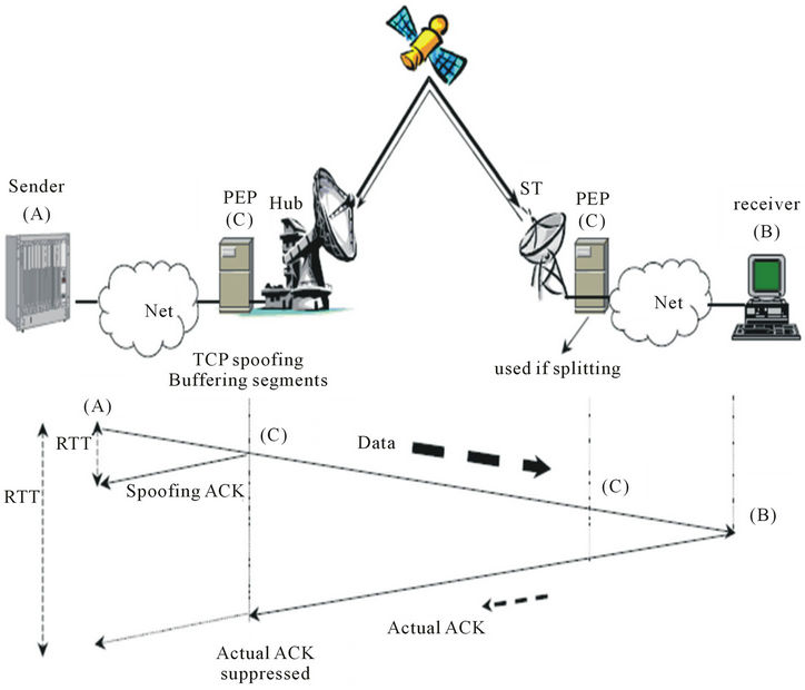
Figure 1. TCP acceleration on satellite links by trusted PEP.
not have access to the payload. So, an end to end secure connection can be provided. Among previous studies, this method can met security requirements more than other methods. The proposed method i.e. ML-IPSec, replaces IPSec single layer model with a multilayer security model. This method is based on dividing IP packets into several zones, using a specific security pattern for each zone (see Figure 2). Thus, the PEPs can access limited parts of IP packet. Authentication and encryption will be done by different keys for each zone area and PEP can only decrypts its own part and after applying changes will encrypt it again. ML-IPSec has encrypted TCP header and application data header part in every IP packet separately and exhibits decrypting key only for final sender and receiver. TCP header decryption key will be accessible for some of trusted PEPs. Therefore, it will establish a secure end to end connection.
1.1. Inbound and Outbound Processing in ML-IPsec
The inbound and outbound processing of an IP datagram in an IPsec gateway is demonstrated through a 2-zone example in Figures 3 and 4.
1.2. Partial In-Out Processing at PEP
In an intermediate node, a packet will go through partial inbound processing and then outbound processing (see Figure 5).
Internet key exchange (IKE) provides a way to agree on the common security protocols, algorithms and keys. Secondly, it guarantees both sides about the identity of the other side [4]. The E2E KEEP protocol, derived from the standard IKE, is considered less vulnerable to attack. It will be easier to configure and deploy, making IPSec VPNs to insecure networks. We used public key technology to meet the key management requirements of insecure networks. More specifically, we choose to develop a PKI for managing X. 509 public key certificates and certificates Revocation lists (CRLs) issued to the network nodes. The IKE protocol contains two phases: in the first phase a secure channel between both sides can be established, while in the second IPSec Security Associations (SAs) can be directly negotiated. In RFC 2409 [5] four different authentication methods for Phase I protocols are defined: pre-shared key, public key signature, public key encryption, and revised public key encryption. The phase II is protected by Phase I SA; it does not need to provide its own authentication protection, allowing a fast negotiation.
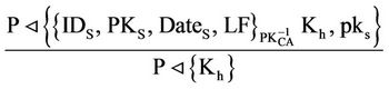
A certificate defined in X. 509 contains the user’s public key and other information and a signature of this information by CA (Certificate Authority) [6]. Three certificate examples are given below:
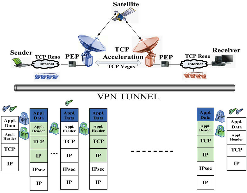
Figure 2. VPN tunnel and multilayer IP security model.
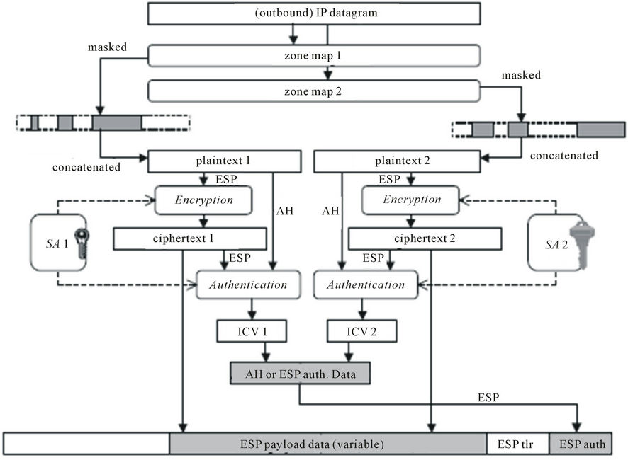
Figure 3. Outbound ML-IPsec processing.
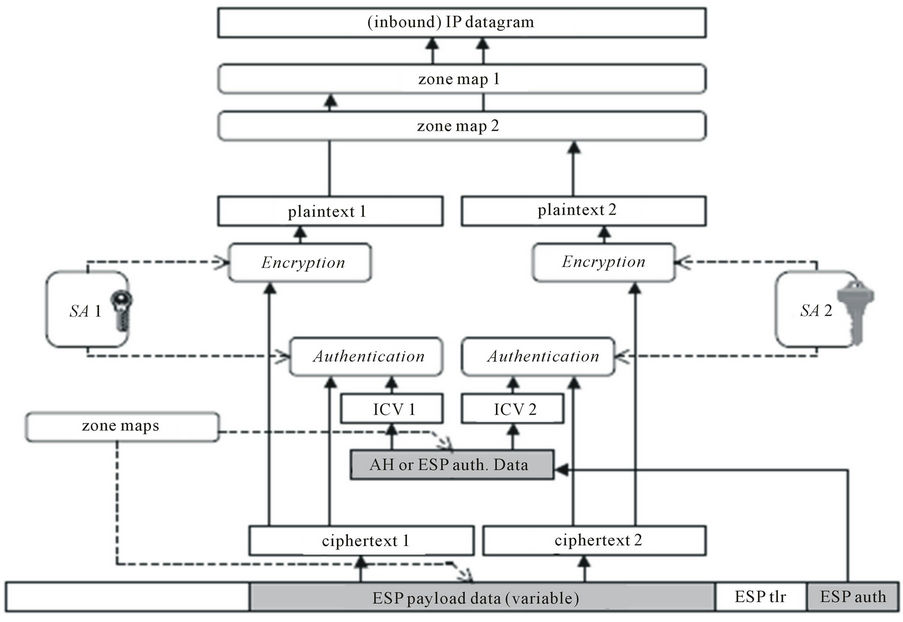
Figure 4. Inbound ML-IPsec processing.
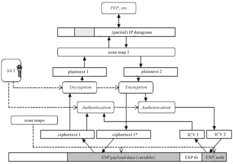
Figure 5. Partial in-out ML-IPsec processing.
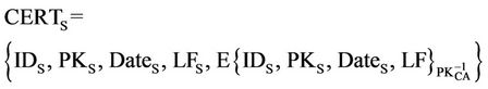
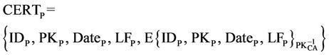
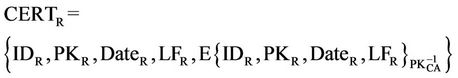
In these expressions, CERTS represents the certificate of S, CERTP represents the certificate of P, and CERTR represents the certificate of R and CERTCA represents the certificate of CA, in Which IDX means the identity of entity X, PKX is the public key of entity X,  is the private key of entity X, DateX is the issue date of the certificate to X, and LFX is the life time.
These data are signed by CA using its private key  and the data in CERTCA are signed by the top level certification authority using its private key
 . E{Y}x indicates that “Y” is encrypted with the asymmetric key “X”. The certificate hierarchy takes the form of a multiple tree structure (see Figure 6). Each tree has a top level certification authority (TLCA) at the root, zero or more layers of middle-level CAs (MLCAs), and a layer of low-level CAs. Each low-level CA owns one or more contiguous blocks of IP addresses, and is responsible for issuing certificates to the nodes with their IP addresses falling in the ranges. Different low level CAs may be dedicated to issue certificates to nodes. TLCAs and MLCAs in different trees may be linked by cross certificates. These cross certificates establish the verification paths between leave certificates in this case a certificate should contain CA’s basic information and the public key of TLCA and MLCA in order to validate the certificate. Here, we do not discuss these details.
2. A Scheme of the Proposed Protocol
In this section, we present the scheme of our protocol [6]. The proposed protocol includes two parts, first part, negotiation between Sender and PEP (see Figure 7), and second part, negotiation between Sender and Receiver (see Figure 8) [7].
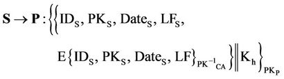
2.1. First Part of E2E KEEP
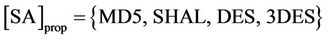
Messages (1) and (2) carry out the parameter negotiation. In message (1), the sender generates a random number, cookie-S (CS), and sends the CS in the first message to the PEP. The [SA]prop includes a list of proposals to the PEP that the sender sends, for example encrypt arithmetic (e.g., DES, 3DES) and authentication arithmetic (e.g., MD5, SHA-1). In message (2), the PEP generates, CP and Usually, CP is generated from some local secret,
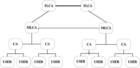
Figure 6. Certificate hierarchy.
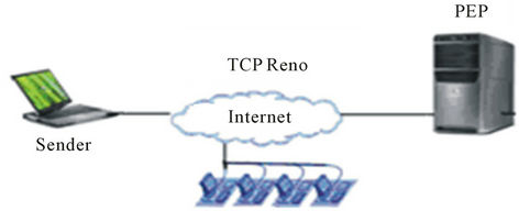
Figure 7. Negotiation between sender and PEP.
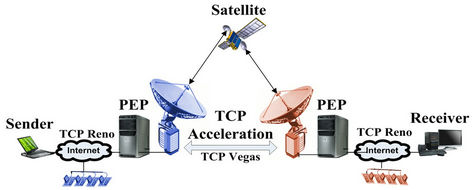
Figure 8. Negotiation between sender and receiver.
some unique information about the PEP (e.g., CP = Hash (source & dest IP addrs, CS ports, P’s local secret)), and possibly other local state information and sends it to the supposed sender. In [SA]cho, PEP either chooses one and only one proposal from the list and sends its choice to the sender or rejects the entire list and sends back an error in the second message. The sender includes
Step 1: The sender generates a random number, cookie CS and proposes SA. Where:
Step 2: The PEP generates cookie Cp, chooses one and only one proposal from the list in [SA]prop. Then, he sends CS, CP, [SA]cho and CERTP to the supposed sender.
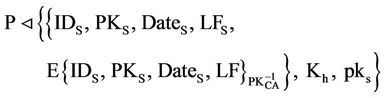
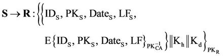
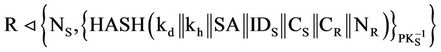
Step 3: After receiving the message, Sender should validate cookie CP and certificate CERTP using the public key of CA. If they are not valid, Sender terminates the execution. Sender generates a header key “Kh” and uses the public key of PEP to encrypt the message CERTS||Kh, Otherwise, where “||” means concatenation. Then, Sender sends message (3) to PEP.
Step 4: After receiving message (3) from Sender, PEP decrypts it to get CERTS and Kh. Then, PEP verifies the validity of certificate CERTS using the public key of CA. If it is invalid, PEP terminates the execution. Otherwise, PEP generates a nonce NP and encrypts it with the public key of Sender. Finally, PEP sends these messages to Sender.
Step 5: After receiving message (4) from PEP, sender opens the message, decrypts it to get NP. Then, sender generates SIG (S) and a nonce NS. Sender encrypts NS with the public key of PEP then sender generates and sends those to PEP, where:
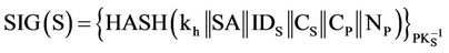
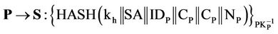
Step 6: After receiving message (5) from sender, PEP validates SIG (S). If it is valid, PEP generates SIG (P) and send it to sender, where:
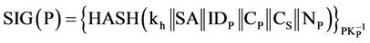
Then sender validates SIG (P) if it is valid, sender will sure PEP is authenticated. If it is not invalid, sender terminates the execution (see Figure 9).
2.2. Second Part of E2E KEEP
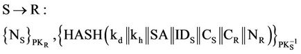
Key exchange between sender and receiver is same as sender and PEP, but here sender generate header key as well as data key then send those to receiver (see Figure 10).
3. Proof of the Concept: Protocol Analysis
It is important to make sure there are no security flaws in the protocol. Thus, this protocol must be analyzed. The BAN-logic is one of the methods for the analysis of cryptographic protocols (see Table 1) [9]. The analysis of the protocol involves applying a number of rules [10,11]. Now we can apply the logical postulate rules to each message with assumptions.
3.1. Negotiation Analysis between Sender and PEP
We start with the assumptions in Figure 11.
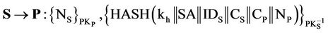
Massage 3:
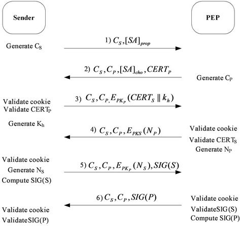
Figure 9. Key exchange between sender and PEP.
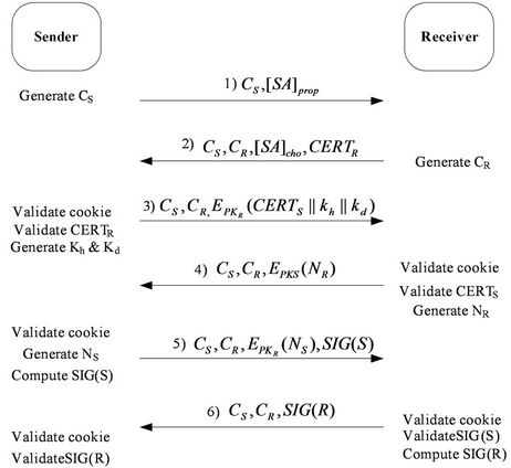
Figure 10. Key exchange between sender and receiver.
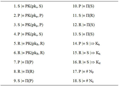
Figure 11. Initial assumption.
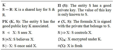
Table 1. BAN symbols.
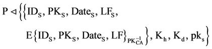
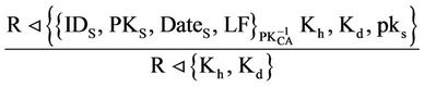
After receiving message (3) from S and from the public key rule (PK) [12]:
Now from the s raying rule (S):
P can see header key: Kh
Massage 4:
P®S: {NP}
After receiving message (4) from S and from the public key rule (PK):
S  {NP}
{NP}
Massage 5:
After receiving message (5) from S and from the public key rule (PK):
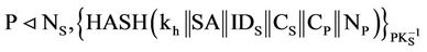
Now P can see sender’s signature P  σ (H (Kh ··· NP), S)
From the Reading of Signature rule (RS), P can see hash of session key and secret nonce “NP”.
P  H((Kh, ···, NP))
After receiving message (5) from S and from the public key cryptographic system rule (PKCS), P deduces:
P |º S |~ ((Kh, ···, NP))
P |º # NP
From the nonce verification (NV) rule P |º # NS, P |º S|º (Kh, ···, NP)
From the freshness distribution rule (FD), P deduces:
P |º # Kh
P believes that the session key is valid.
Kh
P |º (S « P)
Massage 6:
S can see PEP’s signature S v σ (H (Kh ··· NS), P)
From the Reading of Signature rule (RS), S can see hash of session key and secret nonce “NS”.
S v H (Kh ··· NS)
P |º П (P)
After receiving see hash of session key and secret nonce” NS” from P, S deduces:
S |º P |~ (H (Kh ··· NS))
S |º # NS
From the freshness distribution rule (FD), S deduces:
S |º# H (Kh ··· NS)
Now P has been authenticated and S believes P.
S |º P Thus each participant is believes both that the key is valid. Our analysis achieves this result, since we have derived this goal:
Kh
S |º P|º (S « P)
3.2. Negotiation Analysis between Sender and Receiver
Again we start with the assumptions in Figure 11.
Massage 3:
After receiving message (3) from S and from the public key rule (PK):
Now from the saying rule (S):
R can see header and data keys: Kh, Kd
Massage 4:
R®S: {NR}
After receiving message (4) from R and from the public key rule (PK):
S  {NR}
{NR}
S |º # NR
Massage 5:
After receiving message (5) from S and from the public key rule (PK):
Now R can see sender’s signature R  σ (H (Kh, Kd, ···, NR), S)
From the Reading of Signature rule (RS), S can see hash of session key and secret nonce “NR”.
R  H (Kh, Kd, ···, NR)
After receiving message (5) from S and from the public key cryptographic system rule (PKCS), R deduces:
R |º S |~ (Kh, Kd, ···, NR)
R |º # NR
From the freshness distribution rule (FD) and Nonce Verification (NV), R deduces:
R |º # (Kh, Kd)
R believes that the header and date keys are valid Kh
R |º (S « R)
Kd
R |º (S « R)
Massage 6:
R ® S: 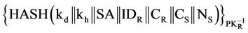
S can see Receiver’s signature S v σ (H (Kh, Kd, ···, NS), R)
From the Reading of Signature rule (RS), S can see hash of session key and secret nonce” NS”.
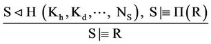
Thus each participant believes both that the key is valid. Our analysis achieves these results, since we have derived this goal (see Figure 12):
Kh
S |º R|º (S « P)
Kd
S |º R|º (S « R)
3.3. Investigate Some Kinds of Conventional Attacks
After discussion on the proposed protocol we investigate some kinds of conventional attacks to the network and study the security level of proposed protocol proving that it is a secure protocol against such attacks [7].
1) Man-In-The-Middle
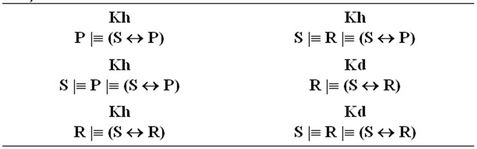
Figure 12. Final goals.
The Man-In-The-Middle is an attack in which an intruder can read and modify the data transferred between two parties without letting none of them know that the link between them has been compromised. By far the attacker can observe and intercept the exchanged messages between the two victims. MITM attacks occur due to the lack of authentication or weak authentication being performed between the two legitimate parties involved in a transaction or communications session. To prevent the insertion of messages, the E2E KEEP protocol is designed. Any deletion will render the message invalid and consequently no partial SA will be created, Strong authentication of the parties prevents a SA from being established with parties other than the intended ones.
2) Denial of Service Denial of Service attack is one in which the system’s resources become depleted and the system would not be useful for legitimate users anymore. In public networks, computers are vulnerable to denial of service attacks. A cookie pair at header is used to protect computing resources which with respect to efficiency of resource usage is comparable with dropping artificial messages before computing intensive public key operations. It is impossible to attain an absolute denial of service protection but the design of E2E KEEP makes situation easier to handle.
3) Replay/Reflection Replay or Reflection attack is a situation in which the network traffic is replayed by a third party after being recorded. E2E KEEP protocol requires the cookies to include a time variable material which facilitates the detection of replay.
4) Connection Hijacking The connection hijacking is an attack in which a third party steals a link by jumping to the middle of transacttion. The E2E KEEP protocol is protected from the connection hijacking by linking the authentication, key exchange, and security association exchanges. The linking of exchanges renders the connection useless for a third party attacker after authentication is accomplished and the attacker cannot play the role of an authenticated party during key exchange or security association exchange.
4. Simulation
After designing E2E KEEP and providing guarantee for being secure implementation of protocol was done using C# for verifying accuracy of its function. In this section the schematics of Sender, PEP and Receiver agent before and after key exchange has been shown (see Figures 13 and 14). In the end, it was seen E2E KEEP works properly.
Part of C# code which has used in implementation has been shown in Figure 15.
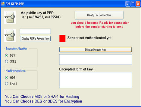
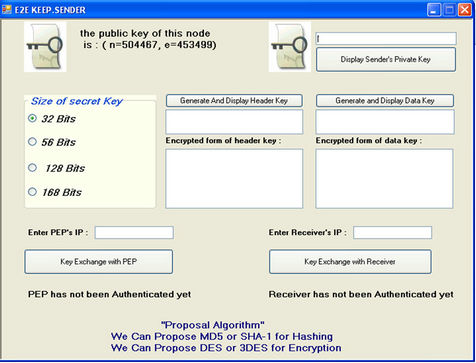
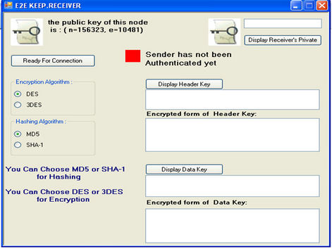
Figure 13. Schematics of sender, PEP and receiver before key exchange.
5. Conclusion
Key exchange and distribution algorithm not only authenticate the actual identity of the sender and receiver, but also enhance the security criteria of the transfer. In this paper, we present a new authentication and key exchange protocol, it provides an end to end accelerated secure connection over satellite links. This protocol en
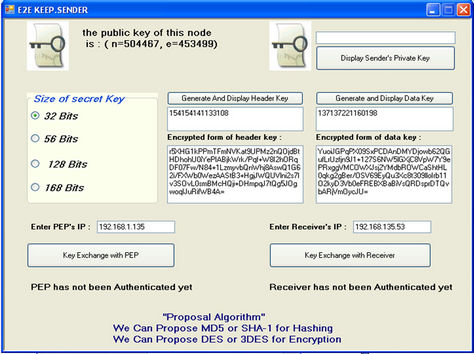
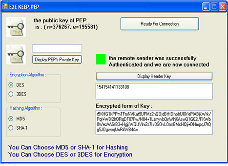
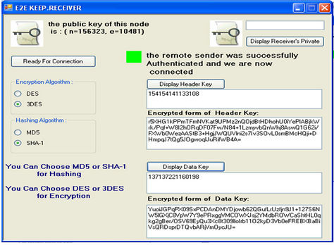
Figure 14. Schematics of sender, PEP and receiver after key exchange.
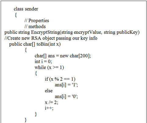
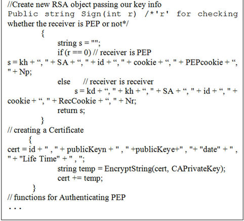
Figure 15. Part of C# code for sender agent.
hances the data transfer security, and provides a more secure connection. First the protocol is presented, after which is modelled in the message-format used in the BAN-logic, the analysis is started with an overview of the goals of the protocol together with the assumptions. Our proof was based upon logic. BAN logic found a proof of correctness. The logic guided us in identifying mistakes and suggesting corrections. The analysis of the protocol is then given and finally the protocol is implemented. In conclusion we can say that our protocol is safe.
REFERENCES
- P. E. Olechna and P. Feighery, “Virtual Private Network Issue Using satellite Based Networks,” IEEE Military Communication Conference, Reston, Vol. 2, 28-31 October 2001, pp. 785-789.
- D. Demirel, F. Alagoz and M. Ufuk, “IPsec over Satellite Links: A New Flow Identification Method,” 7th IEEE International Symposium on Computer Network, Cambridge, 24-26 July 2006, pp. 140-145.
- Y. Zhang, “A Multilayer IP Security Protocol for TCP Performance Enhancement in Wireless Network,” IEEE Journal on Selected Areas in Communications, Vol. 22, No. 4, 2004, pp. 767-776. doi:10.1109/JSAC.2004.825993
- D. Harkins and D. Carrel, “The Internet Key Exchange (IKE). [R] RFC2409,” 1998.
- R. Housley, W. Ford, W. Polk and D. Solo, “Internet Public Key Infrastructure, Part I: X. 509 Certificate and CRL Profile,
[R],” IETF PKIX Working Group, 1997. - H. Fereidooni, H. Taheri and M. Mahramian, “A New Authentication and Key Exchange Protocol for Insecure Networks,” The 5th International Conference on Wireless Communications, Networking and Mobile Computing, Beijing, 24-26 September 2009, pp. 1-4.
- H. Fereidooni, A. Parichehreh, H. Taheri, M. Mahramian and B. Eliasi, “ML-IPSec+: An End to End Accelerated VPN for Satellite Links,” International Journal of Computer Science and Network Security, Vol. 9, No. 1, 2009.
- J.-M. Zhu and J.-F. Ma, “An Internet Key Exchange Protocol Based on Public Key Infrastructure,” Journal of Shanghai University, Vol. 8, No. 1, 2004, pp. 51-56. doi:10.1007/s11741-004-0012-8
- M. Burrows, M. Abadi and R. Needham, “A Logic of Authentication: ACM Operating Systems Review,” DEC System Research Center Report Number 39, Palo Alto, 1989.
- T. Kyntaja, “A Logic of Authentication by Burrows, Abadi and Needham,” Science Helsinki University of Technology, Tehran. http://www.tml.tkk.fi/Opinnot/Tik-110.501/1995/ban.html
- W. Teepe, “BAN Logic and Hash Functions,” Autonomous Agents and Multi-Agent Systems, Vol. 19, No. 1, 2009, pp. 76-88. doi:10.1007/s10458-008-9063-8
- Jan Wessels, “Application of BAN-Logic,” Technical Report, CMG Public Sector B.V., 19 April 2001.