Journal of Biomedical Science and Engineering
Vol. 5 No. 3 (2012) , Article ID: 18104 , 5 pages DOI:10.4236/jbise.2012.53018
An implantable electrical stimulator for phrenic nerve stimulation
![]()
1Islamic Azad University, Qazvin Branch, Qazvin, Iran
2Shahed University, Tehran, Iran
Email: sh.sardarzadeh@yahoo.com, pooyan@shahed.ac.ir
Received 25 October 2011; revised 28 November 2011; accepted 10 January 2012
ABSTRACT
Phrenic nerve stimulation is a technique whereby a nerve stimulator provides electrical stimulation of the phrenic nerve to cause diaphragmatic contraction in patients with respiratory failure due to cervical spinal cord injury. This paper presents an eigth-channel stimulator circuit with an output stage (electrode driving circuit) that doesn’t need off-chip blocking-capacitors and is used for phrenic nerve stimulation. This stimulator circuit utilizes only 1 output stage for 8 channels. The proposed current generator circuit in this stimulator reducing to a single step the translation of the digital input bits into the stimulus current, thus minimizing silicon area and power consumption. An 8 bit implementation is utilized for this current generator circuit. The average pulse width for this eightchannel stimulator with 1 mA current, 20 Hz frequency and 8 bits resolution, is 150 - 300 µs. The average power consumption for a single-channel stimulation is 38 mW from a 1.2 V power supply. This implantable stimulator system was simulated in HSPICE using 90 nm CMOS technology.
Keywords: Phrenic Nerve Pacing; Current Generator; Blocking Capacitor; Output Stage
1. INTRODUCTION
Cervical spinal cord injury or dysfunction of the brainstem often results in interruption of the motor pathways from the respiratory center in the medulla to the inspiratory muscles causing respiratory failure. Patients with such failure are usually managed with the use of artificial ventilators. Nevertheless, chronic use of ventilators is not physiological, simply causes infections, and limits the patient’s activities [1]. It has been known for a long time that phrenic nerve pacing with an implanted electric device is a practical solution for such patients and causing diaphragmatic contraction [2]. This method first explained theoretically by Duchenne in 1872 as the “best means of imitating natural respiration”, the pioneering work came in the late 1960s by Glenn et al. subsequently, in combination with Avery Biomedical Devices (Commack, NY, USA), the first phrenic nerve stimulators were brought into commercial distribution [3].
The stimulation of phrenic nerve is typically accomplished by delivering frequent artificial stimulation pulses. The stimulation phase of the pulse depolarizes the neurons of the goal tissue and starts the action potential, which propagates along the nerve fiber and elicits the muscle response.
The main concern for any implantable stimulator intended for chronic use is safety. For instance, the stimulator output stage which directly attaches to the electrodes should not fail as this may result in tissue injury due to electrolysis. Hence, three methods of protection that are monitoring, using blocking capacitors and capacitive electrodes have reported [4]. IN the method of using blocking-capacitor, these capacitors limits the charge on the electrodes to Q = C·V, where C is the capacitance and V is the power supply voltage. The value of the blockingcapacitor depends on the necessities for a definite stimulation. For example, to recover phrenic nerve function, stimulus currents of about 1 mA intensity and 150 µs pulse width, are required.
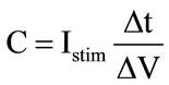 (1)
(1)
where I is the stimulus current amplitude, Δt is the stimulus current pulse width and ΔV is the change in voltage across the blocking-capacitor. For the above numerical example, to limit the capacitor voltage drop, to say 0.5 V, a 0.3 µF capacitor is required. Obviously, this capacitor is off-chip, so, with constant Istim and ΔV, the capacitor value is proportional to the time the stimulus current flows through it. For example, if the 1 mA stimulus current consists of a train of 50 ns pulses, only a 100 pF capacitor is required for 0.5 V drop across it, thus the blocking-capacitors can be integrated on-chip (HFCS technique) [4].
The other required circuit for stimulation of phrenic nerve is current generator circuit. Some commonly current generator circuits for implantable neural stimulators have been reported in [5]. Desirable characteristics for a current generator circuit for use in this application are small voltage compliance, high output impedance, good linearity, low power consumption and small silicon area.
As the Japanese experience shows we can utilize the spinal cord stimulator for phrenic nerve pacing [2]. But we have to modify the pulse width to 150 - 300 µs. In this paper, we use an 8-channel implantable stimulator for phrenic nerve pacing that utilizes current generator circuit and the output stage circuit proposed in [5]. Unlike the current generator circuit in [5], an 8-bit implementation is used for the current generator circuit in this paper and also the neural stimulator utilizes only one output stage for 8 channels. We have simulated this neural stimulator in HSPICE using 90 nm CMOS technology.
2. DESCRIPTION OF THE IMPLANTABLE STIMULATOR
An 8-channel stimulator employing the current generator and the output stage circuit described in [5], has been designed using 90 nm CMOS technology. It was simulated by HSPICE. The block diagram of the stimulator is shown in Figure 1. As you can see it consists of the 8-bit current generator (DAC) (Figure 2), one ring oscillator, some
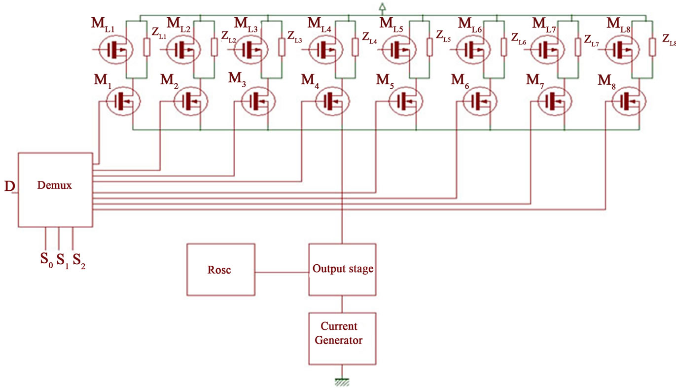
Figure 1. Block diagram of the stimulator circuit.
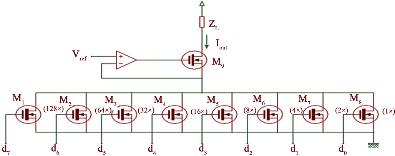
Figure 2. Proposed current generator. An 8-bit implementation is shown.
digital control logic, demultiplexer and the electrode driving circuit (Figure 3). The constant current Istim (generated by the current generator circuit) after passing from the output stage, is multiplexed between the eight loads ZL1 - ZL8 .The ring oscillator supplies the switching frequency of the output stage. The frequency of ring oscillator can be varied between 1 and 20 MHz. The output stage contains 2 × 100 pF blocking capacitors. The average power consumption for a single channel stimulation is 38 mW from a 1.2 V power supply.
Unlike the current generator circuit in [5], the proposed current generator circuit in this paper is utilized an 8-bit implementation and the operation of this circuit is
 (a)
(a)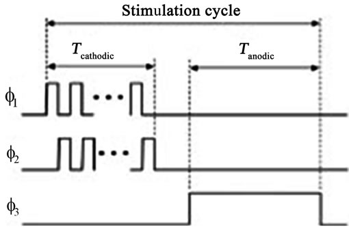 (b)
(b)
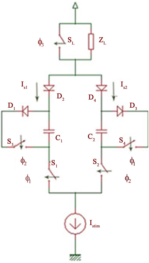
Figure 3. (a) Proposed stimulator output stage utilizing the HFCS technique and passive discharge; (b) Timing wave-forms [5].
as followes. When the circuit is on, the gate-source voltage of each transistor is VDD, therefore the drain current of every transistor (of aspect ratio W/L) when the bias voltage is small, and every transistor operates in deep triode region, may be calculated from
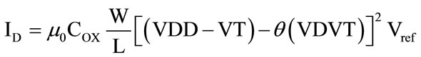 (2)
(2)
and for an 8-bit implementation (because
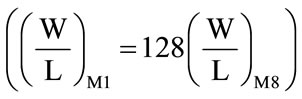 , the output current may be given by
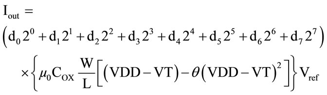 (3)
(3)
where di equals 1 or 0; d0 is the LSB and d7 is the MSB. The advantage of this circuit is that no analog biasing or linearity compensation circuits are needed. This signifycantly reduces complexity, which reduces silicon area and power consumption. The output stage utilizing HFCS technique and passive discharging explained in [4]. The operation of the circuit is as follows. When clock phase Φ1 is on, S1 and S4 are closed and S2, S3 and SL are opened. Therefor current Istim flowes in the direction of VDD, ZL, D2, C1 and forming current Is1 through the load and the blocking capacitor C1 is charged up. On the other side, D3, C2 and S4 form a closed path for discharging C2. During clock phase Φ2, S2 is closed and S1, S4 and SL are opened. Current Istim flowes in the direction of VDD, ZL, D4, C2 and forming current Is2 through the load and C2 is charged up when C1 is discharging in the closed path D1, C1 and S3.
The summation of the high-frequency currents Is1 and Is2 for the entire length of the cathoadic phase results in the long cathodic current through the load [see Figure 4(a)]. For the clock phase Φ3, SL is closed and the other
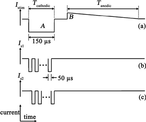
Figure 4. Generation of the active cathodic current by summation of two high frequency current pulse trains [5].
switches are opened and the load ZL is passively discharged. Switches S1 and S2 may be implemented with nMOS transistors whereas switches S3, S4 and SL with pMOS transistors.
In this paper we use only 1 output stage for 8 channels, while, the implantable stimulator in [5] utilizes 4 output stage circuits for 4 channels. This characteristic minimizes silicon area. The generation of clk1 (Φ1) and clk2 (Φ2) by an on-chip oscillator and logic gates is shown in Figure 5.
3. SIMULATED RESULTS
The output of the current generator circuit is shown in Figure 6. For all of the DAC input codes (Vref = 18 mV). In order to maintain constant current of 1 mA, the circuit requires only 0.4 V across it. This shows that the proposed current generator circuit has really very small voltage compliance even for currents in the milliampere range.
The linearity performance of the circuit is shown in Figure 7. Since the proposed current generator circuit achieves high linearity without any biasing or compensation circuits, it is very area-efficient.
The stimulator output stage circuit has been simulated using a 1.2 V power supply. Figure 8 shows a snapshot of the simulation current waveform through a load for a constant current source of 1 mA. The repetition rate was 20 Hz with 150 µs active cathodic phase, 150 µs inter phase delay (between the cathodic phase and the anodic phase) and 49.7 ms passive anodic phase (we show only 30 ms of 50 ms, because 150 µs is much smaller than 50 ms). The charge generated in the active cathodic phase is neutralized by the charge generated in the passive anodic phase. The glitches evident on the load current are due to switching delays. However, these glitches only last a fraction of the active cathodic phase and are thus not considered a problem at all. The output of the output stage circuit when the current from the current generator was set to 1 mA has also shown in Figure 9. Table 1 compares the characteristics of the proposed implantable stimulator with the circuit in [5].
4. CONCLUSION
We have introduced a block diagram for phrenic nerve stimulation. All circuits of this block diagram are simu-
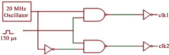
Figure 5. Generation of clock phase Φ1 and Φ2.
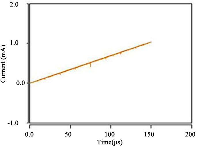
Figure 6. The output current of the 8-bit current generator circuit (DAC). There are 255 steps until 1 mA.
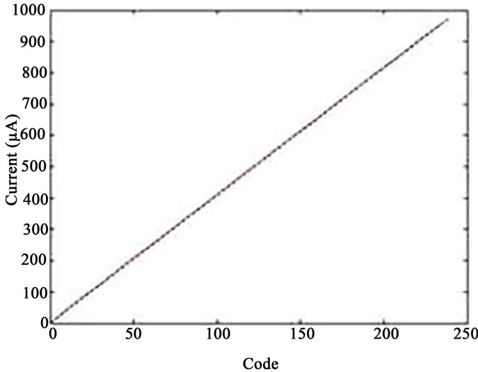
Figure 7. The linearity performance of the current generator circuit.
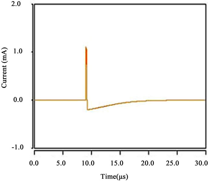
Figure 8. The output of the output stage circuit using a constant 1 mA current source.
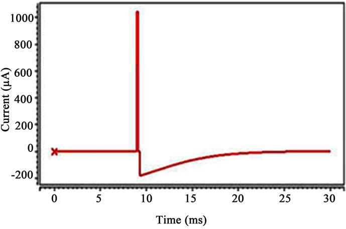
Figure 9. The output of the output stage circuit when the current from the current generator was set to 1 mA.
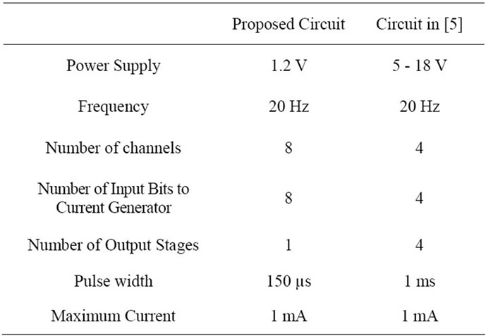
Table 1. Comparison of proposed circuit with the circuit in [5].
lated in HSPICE using 90 nm CMOS technology. Proposed current generator circuit has one step to translate the digital input bits to output current and is an 8-bit current generator. High linearity, small voltage compliance, low power consumption and small silicon area are characteristics of this current generator circuit. Proposed output stage circuit uses on-chip blocking capacitors with HFCS technique, which allows the physical size of the stimulator implant to be dramatically reduced. We use only 1 output stage for 8 channels.
![]()
![]()
REFERENCES
- DiMarco, A.F. (2009) Phrenic nerve stimulation in patients with spinal cord injury. Jornal of Respiratory Physiology & Neurobiology, 169, 200-209.
- Taira, T., Takeda, N., Itoh, K., Oikawa, A. and Hori, T. (2003) Phrenic nerve stimulation for diaphragm pacing with a spinal cord stimulator. Elsevier, 59, 128-132.
- Khong, P., Lazzaro, A. and Mobbs, R. (2010) Phrenic nerve stimulation: The Australian experience. Journal of Clinical Neuroscience, 17, 205-208. doi:10.1016/j.jocn.2009.06.012
- Liu, X., Demosthenous, A. and Donaldson, N. (2007) A fully integrated fail-safe stimulator output stage dedicated to FES stimulation. IEEE International Symposium on Circuits and Systems, New Orleans, 27-30 May 2007, 2076-2079. doi:10.1109/ISCAS.2007.378507
- Liu, X., Demosthenous, A. and Donaldson, N. (2008) An integrated implantable stimulator that is fail-safe without off-chip blocking-capacitors. IEEE Transactions on Biomedical Circuits and Systems, 2, 3.