Engineering
Vol.4 No.12(2012), Article ID:25857,4 pages DOI:10.4236/eng.2012.412111
Mechanical Validation of Perfect Tibia 3D Model Using Computed Tomography Scan
1Mashhad Branch, Islamic Azad University, Mashhad, Iran
2Department of Mechanics, Mashhad Branch, Islamic Azad University, Mashhad, Iran
3Department of Orthopedic Surgery, North Khorasan University of Medical Sciences, Bojnurd, Iran
Email: ehsan_t683@yahoo.com
Received September 24, 2012; revised October 25, 2012; accepted November 6, 2012
Keywords: Human Tibia Bone; Finite Element; 3D Model; Mechanical Validation
ABSTRACT
In this paper, the Von Mises stresses and stiffnesses measured by experiments on a human cadaveric tibia and composite ones compared to those predicted by a FE model based on the same bone. Modeling of exact geometrical tibia including cortical and spongy bone using human bone CT scan images and mechanical validating of obtained model, is the aim of this study .The model produced by the current study supplies a tool for simulating mechanical test conditions on human tibia.
1. Introduction
Tibia has most statistics in skeleton bone fractures. Injuries to the human lower extremities are mostly due to the collision of a vehicle and pedestrian, which results in fractures of long bones, injuries to the knee and ankle. Different injury mechanisms can be seen in long bones. Bending and torsion moments have been considered as major affecting factors [1]. During the last three decades, impact biomechanics in the collision of vehicle-pedestrian has been studied widely in order to recognize the injury mechanisms in human limbs, reaction of lower extremities to the mechanical loads and obtaining information on the strength of different human bone tissues [2]. Scientists have made many researches on mechanical behavior and strength of tibia. Mechanical software are very helpful for performing biomechanical tests and orthopedic conclusions to apply for designing biomedical engineering devices especially various types of fixators. Several studies have been carried out on FE models of the human tibia [3-6]. Some of them report convergence tests, but none of them reports a comprehensive and quantitative validation of the model, verifying FE results against experimental results.
Tibia has complicated geometry and material properties. So obtaining trustable computer models of the bone has been major problem in modeled based researches. Thus most of researchers have simplified it considering it as a cylinder, defining one material and ignoring spongy bone and bone marrow in Models. Defining material of bone in software has been important in biomechanical behavior results [7].
Previously 3D model of tibia was created with the geometry of the real bone by using scan images of the human left leg ignoring spongy bone and bone marrow [8]. In another research, type of fracture in tibial shaft under transversal and torsional impacts had been predicted by using a cortical shell model ignoring the Effects of the spongy bone [9].
Mechanical torsion and bending response of cadaveric tibia with commercial composite ones have been compared in a research [10] which results showed significant differences. This can be meant that composite bones may not be reliable for some mechanical experiences.
The aim of current study was to explain modeling procedure of human right tibia bone using CT scan images and obtaining results of bending and torsion of it in condition of previous study on cadaveric ones [10]. This was done using Mimics 10.01, Solid Works 2012 and Abaqus 6.11-1 software.
2. Method
Modeling
Modeling process consisted of some main steps (Figure 1). As illustrated, modeling started using computed tomography (CT scan) Images. CT scan of a normal 32 years old man with no skeleton problem was used. Images imported to Mimics 10.01 and in this software tibia was separated from fibula, femur and surrounding mus-

Figure 1. Modeling process of this study which obtained a 3D perfect model of tibia bone in Abaqus software.
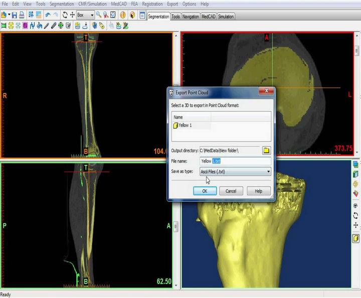
cles. The software recognizes the hardness and softness of materials by their density and showed them with the color contrast separations. After some required changes, the model was exported as a text file of points cloud (Figure 2(a)).
Abaqus was not applicable for a text file. It just could make a shield from it, so in order to have a perfect model of tibia, including the cortical and trabecular parts, firstly the text file was imported to Solid works (Figure 2(b)) and extension of the nodes and volume construction was done. Obtained result saved and exported from Solid works as Para-solid format file which was a tibia with the length of 375 mm and ready to import to Abaqus software.
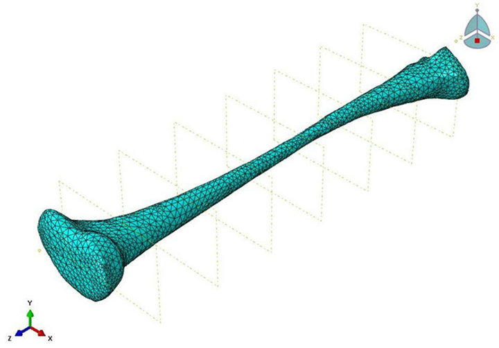
The model was a composite which simulated as a real human tibia considering cortical and trabecular bone. Anisotropic material properties of human long bone [11] were defined (Table 1). Meshing was done using 67,496 hexahedral elements for cortical and 31,371 tetrahedral elements for trabecular parts of the model (Figure 3).
Four points bending simulation with load of 500 N and actuator speed of 0.05 mm/s was applied so that loading was interrupted when deflection of 0.5 mm was reached. The torque was applied with actuator speed of 0.23 mm/s so that the knee was twisted towards intra-rotation until rotation of 5˚ was reached. Then bending and torsion stiffness of 3D model was calculated to compare with the results of real cadaveric bone stiffness.
 (a)
(a) (b)
(b)
Figure 2. Tibia bone modeled in Mimics using CT scan images of lower limbs of a 32 years old man, ready to export as a text file of points cloud (a) and the text file defined in solid works software (b).

Table 1. Material properties used in the bone 3D model [11].
 (a)
(a)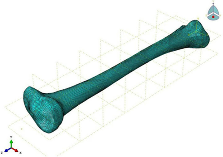 (b)
(b)
Figure 3. Tibia trabecular part was meshed in 67,496 hexahedral elements (a) and cortical part was meshed in 31,371 tetrahedral elements (b) in Abaqus.
3. Results
Stress spectrums were obtained from four points bending test and torsion loading on the 3D model (Figure 4). Bending stiffness in two anterior-posterior and lateral medial planes and torsional stiffness were calculated (Table 2) using following formulas:
• Bending stiffness
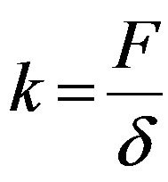 (1)
(1)
• Torsional stiffness:
 (2)
(2)
which F was the force applied on the Bone, K was bending or torsional stiffness, δ was displacement, M was moment and θ was degree of rotation.
4. Discussion
The finite element bone model used in this study was obtained from whole bone material modeling without ignoring lower strength material of spongy bone and marrow. The model was verified by its stiffness compared with the cadaveric one measured previously [10].
For validation and verification the mechanical responses of the model, the obtained stiffnesses were compared with measured ones of a good cadaveric right tibia, also with average of 8 composite tibias results that previously had been studied [10] (Figure 5).
As illustrated (Figure 5), stiffness results of anteriorposterior and lateral-medial direction in bending and torsion tests of this study were significantly close to cadaveric ones.
5. Conclusions
This study compared the Von Mises stresses and stiffnesses measured by experiments on a human cadaveric tibia and composite ones to those predicted by a FE model based on the same bone.
 (a)
(a)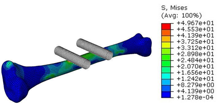 (b)
(b) (c)
(c)
Figure 4. Von Mises stresses spectrum in Lateral-medial (a) and anterior-posterior (b) planes of four point bending and 5˚ Torsional loading (c).
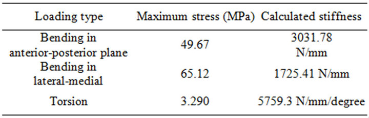
Table 2. Maximum Von Mises stresses and calculated stiffnesses in bending and torsional loading.
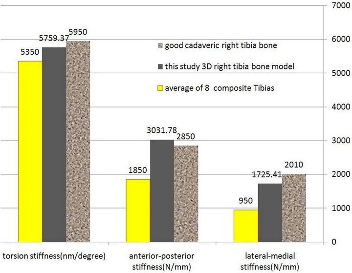
Figure 5. Histogram representation of comparing the obtained stiffnesses of finite element tibia model of this study with cadaveric and composite ones have gotten from other study [10].
The model produced by the current study supplies a tool for simulating mechanical test conditions on human tibia. This has considerable value in reducing the costs of physical testing by preselecting the most appropriate test conditions or most useful prosthetic designs for final mechanical testing. It can also be used to acquire the ability to understand the results of physical testing, by allowing the prediction of those variables difficult or impossible to be measured directly.
6. Acknowledgements
The authors are grateful to Department of Mechanical Engineering, Faculty of Engineering, Mashhad Branch, Islamic Azad University, Mashhad, Iran.
REFERENCES
- J. Shen and X.-L. Jin, “Improvement in Numerical Reconstruction for Vehicle-Pedestrian Accidents,” Journal of Automobile Engineering, Vol. 222, No. 1, 2008, pp. 25-39.
- R. Levine, “Injury to the Extremities,” Springer-Verlag, Berlin, 1993, pp. 460- 491.
- G. N. Duda, F. Mandruzzato, M. Heller, J. Goldhahn, R. Moser, M. Hehli, L. Claes and N. P. Haas, “Mechanical Boundary Conditions of FractureHealing: Borderline Indications in the Treatment of Unreamed Tibial Nailing,” Journal of Biomechanics, Vol. 34, No. 5, 2001, pp. 639- 650.
- G. N. Duda, F. Mandruzzato, M. Heller, J. P. Kassi, C. Khodadadyan and N. P. Haas, “Mechanical Conditions in the Internal Stabilization of Proximal Tibial Defects,” Clinical Biomechanics, Vol. 17, No. 1, 2002, pp. 64-72.
- A. Perillo-Marcone, D. S. Barrett and M. Taylor, “The Importance of Tibial Alignment: Finite Element Analysis of Tibial Malalignment,” Journal of Arthroplasty, Vol. 15, No. 8, 2000, pp. 1020-1027.
- A. Perillo-Marcone, A. Alonso-Vazquez and M. Taylor, “Assessment of the Effect of Mesh Density on the Material Property Discretisation within QCT Based FE Models: A Practical Example Using the Implanted Proximal Tibia,” Computer Methods in Biomechanics and Biomedical Engineering, Vol. 6, No. 1, 2003, pp. 17-26.
- R. Krone and P. Schuster, “An Investigation of Importance of Material Anisotropy in Finite-Element Modeling of the Human Femur,” SAE International, 2006, Paper No. 2006-01-0064.
- B. Sepehri, A. R. Ashofteh-Yazdi, G. A. Rouhi and M. Bahari-Kashani, “Analysis of the Effect of Mechanical Properties on Stress Induced in Tibia,” Department of Mechanical Engineering, IFMBE Proceedings, Vol. 35, 2011.
- B. Sepehri, A. R. Ashofteh-Yazdi, G. A. Rouhi and M. Bahari-Kashani, “Effect of Load Direction on Fracture Type in Tibia an FEM Analysis,” 17th Iranian Conference of Biomedical Engineering (ICBME 2010), Isfaham, 3-4 November 2010.
- L. Cristofolini and M. Viceconti, “Mechanical Validation of Whole Bone Composite Tibia Models,” Journal of Biomechanics, Vol. 33, No. 3, 2000, pp. 279-288. doi:10.1016/S0021-9290(99)00186-4
- S.-H. Kim and S.-H. Chang, “The Finite Element Analysis of a Fractured Tibia Applied by Composite Bone Plates Considering Contact Conditions and Time-Varying Properties of Curing Tissues,” Composite Structures, Vol. 92, No. 2, 2010, pp. 2109-2118. doi:10.1016/j.compstruct.2009.09.051