Engineering
Vol. 4 No. 5 (2012) , Article ID: 19311 , 4 pages DOI:10.4236/eng.2012.45036
Modelling and Parameters Identification of Through-Hole Type Wind Turbine Contactless Sliprings
Department of Electrical and Computer Engineering, University of Auckland, Auckland, New Zealand
Email: aabd104@aucklanduni.ac.nz, {a.hu, n.nair}@auckland.ac.nz
Received March 13, 2012; revised April 10, 2012; accepted April 20, 2012
Keywords: CSS (Contactless Slipring Systems); Transformer Modeling; Contactless Power Transfer; Wind Turbine Pitch Control
ABSTRACT
This paper presents a modelling and parameter identification of through-hole type contactless slipring systems for transferring electrical power for wind turbine pitch control. An equivalent circuit model has been developed from the physical structure and dimensions of the contactless slipring using the duality rules, which is very different form traditional transformer. The circuit inductances are determined by the derived expressions from the system reluctances. In particular, the equivalent resistance representing the core loss of the slipring has been determined using phasor diagram of exciting current. FEM (Finite Element Method) models and practical prototypes are developed for testing and verifications. Both simulation and experimental results have shown that the developed model gives truthful values for numerical calculations in order to obtain the equivalent electric circuit. The effect of fringing flux around the air gap on mutual inductance and the ways of correcting its effects are analysed. The obtained values have shown that the developed models and derived equations are with high accuracy as compared to the FEM simulation and experimental results.
1. Introduction
Recently contactless slipring systems have gained high popularity among researchers for their several advantages as compared to conventional mechanical slipring systems. In a glance, the reliability and long life cycle, in combination with minimum maintenance requirement, are the main advantages of CSS (Contactless Slipring Systems). Use of conventional slipring assemblies is often undesirable, since their inherent high friction characteristics often cause excessive wear and increased maintenance [1]. The contactless slipring solution eliminates many of the disadvantages associated with the conventional systems [2,3].
However, with all the mentioned benefits, contactless slipring systems posed some unusual design constraints. To begin with, the relatively large gap in their magnetic circuit results in a low magnetizing inductance. Again, because of the air gap between primary and secondary windings results in high primary and secondary leakage inductances. Moreover, eddy currents, caused by fringing flux, can be formed in the magnetic material near the gap which could cause losses and local radiation [4]. Therefore, based on CSS features and the mentioned design restrains, having a reliable prediction and an accurate model of the contactless transformer used in such systems is essential for design prejudgments. Moreover, the obtained model is advantageous for theoretical calculations, electrical network simulations, and any further modifications before construction. This helps the designer to have a better understanding about the system and its associated limitations for any possible changes, in order to design the system so as to meet the application requirements. There are other methods such as testing /measurements and FEM analysis that can be used for design analysis. However, the measurement method can only be applied in practical systems and the finite element analysis is only suitable for preliminary calculations and simulations.
The aim of this paper is to obtain a complete procedure and derive the required equations for modeling two types of through-hole contactless transformers. Basic principle of a CSS is presented. This is followed by the effect of the fringing flux generated around the air gaps and the way of correcting this effect. Mathematical equations and developed theory are presented for obtaining the electrical model based on the physical layout. The reluctance equations are summarized for two contactless transformers for numerical calculations. Finite Elements Models are developed and simulation results are presented for the system assessment. A complete procedure of experimental contactless transformer measurements is presented. Two coaxial and face to face designs of a through-hole contactless transformer are prototyped and experimental testing are performed for modelling verification. Finally, to evaluate the theoretical modelling and calculations, a comparison with FEM and experimental results is conducted.
2. Basic Principle of Operation
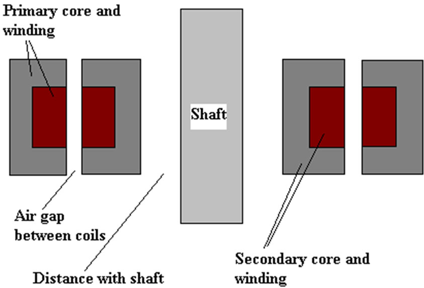
Figure 1 shows two through-hole types (a) coaxial and (b) face to face structures of a contactless transformer. As it can be seen because of the air gap, the secondary can freely move or rotate relative to the primary. The block diagram of this system is demonstrated in Figure 1(c). The whole system includes primary converter, contactless transformer and secondary converter. Generally high frequency resonant converter is adopted at the primary to improve the power transfer characteristics. The secondary converter realizes rectifying and power converting according to the load requirements. A distance between the whole structure and the shaft is considered to avoid any excessive heating the shaft due to fringing flux lines, etc. The revolution of high-frequency switching power conversion allowed the magnetic link to be implemented with reasonably sized components [5]. This new technology creates new possibilities to supply portable devices with electrical energy which has been used in many different applications, each of them having particular specifications, necessities and restrictions.
The air gap is fixed for the first design, while it can be varied by moving the rotating part back and forth for the second design. Usually, for high power and small air gap situations, transformers with magnetic cores in primary and secondary side are appropriate. Other new coupling structures for a contactless transformer with single core and single air gap are proposed for this application [6,7]. In contrast, for large air gap and low power air transformers (coreless) are preferred. A special case is a sliding transformer which can have construction for linear or circular movement. The final configuration of contactless power transfer systems depends also strongly on number of loads to be supplied. In such cases transformer with multi-windings secondary or primary side are used. Because of the air gap, a contactless transformer reveals different features as compared to the typical un-gapped transformer as detailed in the next section.
3. Effect of Air-Gap and Its Correction Rules
Depending on the application, the magnetic coupling structure used in contactless slip-ring systems has different geometry, size and structure that define their performance. Due to the existence of air gap between the
 (a)
(a)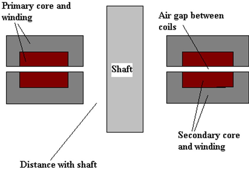 (b)
(b)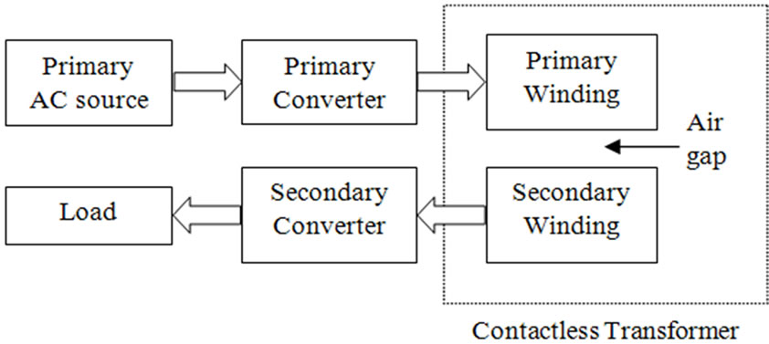 (c)
(c)
Figure 1. Axial contactless transformer structures (a) Coaxial; (b) Face to face; (c) Block diagram of a CSS.
windings, the contactless transformer reveals a low magnetic coupling coefficient. This results in storing a portion of the total supplied energy into the magnetic structure itself (mainly within the air gap) rather than transferring it to the secondary. The energy storage is directly related to the coupling. There are two basic energy storing elements; the magnetizing inductance (inversely proportional to the air gap length) and the leakage inductance (related to the windings layout and relative positioning).
The magnetizing inductance of such a transformer is much lower than that of a compactly coupled counterpart. As a result, in addition to the reflected load current, the primary winding carries an increased magnetizing current, in turn, increasing the primary-side conduction losses. Again, by the reason of air gap inclusion and the availability of alternative magnetic-flux paths (air space) rather than the ideal core path, the contactless transformer also exhibits increased leakage inductance in both windings. The increased leakage inductance, which appears in series with the windings, causes a voltage drop across them, resulting in the reduced voltage gain. At the same time only a portion of the primary current is being reflected to the secondary side as the rest is being drawn by the low magnetizing inductance [8]. Furthermore, whenever an air gap is introduced into a magnetic path, the magnetic field lines will “fringe” outward as they cross the air gap as shown in Figure 2. These fringing fields will increase the effective cross-sectional area Ag of the air gap. One way to correct this effect is by adding the length of the gap to the dimensions of the core center-pole cross-section. To avoid what could be a significant error, the inductance calculation must be based upon the effective gap area rather than the actual center-pole area. Therefore, a range of experiential methods have been developed for correcting this effect. For a core with a rectangular center-pole (cp) with cross-section dimensions (a and b), the effective gap area, Ag is approximately [9] is,
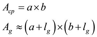 (1)
(1)
Similarly, for a round centre-pole with diameter Dcp,
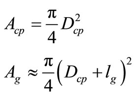 (2)
(2)
Thus, to achieve the desired inductance, the gap area must be modified by using the above correction method.
4. Obtaining Electrical Model from Geometry
The purpose of modeling the transformer as an electrical network is to offer an improved analysis of the transformer performance, simulation, derivation of mathematical equations to put a figure on each aspect of a magnetic component. Moreover, it helps to define the magnitude and location of relevant parasitic magnetic elements to enable prediction of performance effects. The duality method is proposed decades ago and it’s based on finding the equivalent magnetic circuit by identifying the different magnetic flux paths in it. Then using the duality between magnetic and electric quantities, the reluctance model then is converted to an electric equivalent network [10]. Figure 3 shows the flux paths of the contactless transformer used for contactless slipring system. The primary current is flowing in the primary winding sets up an mmf
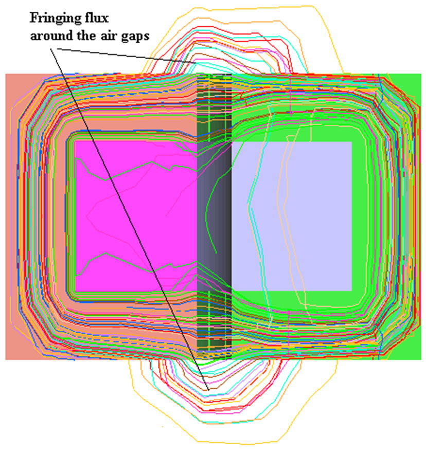
Figure 2. Fringing flux around the air gaps.
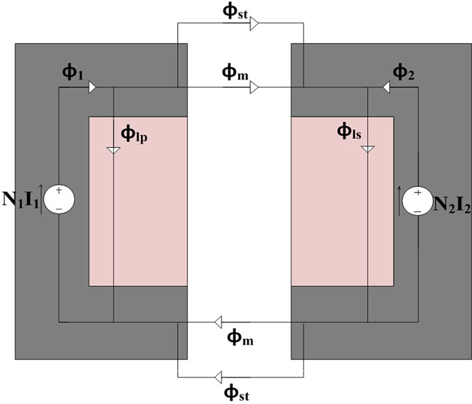
Figure 3. Flux paths of the contactless transformer.
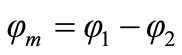
(N1I1) which is considered as a driving mmf. If a load is connected to the secondary winding, then the induced current in the secondary winding produces a back-mmf (NsIs) which its associated flux φ2 opposes the primary flux φ1 (and thus subtract from it) as illustrated in Figure 3. The resultant of these two mmf’s is the working main flux φm (mutual flux) is given by,
 (3)
(3)
Where
 (4)
(4)
Referring to Figure 3; the leakage stray flux lines (φst1 and φst2) in contactless transformer do not have a priori known path, therefore, it is inaccurate to model them with a reluctance network. Thus, fringing fields around the gaps will be ignored, except the effective gap area might be corrected to take the fringing field into account as presented in Section 3. Therefore, the total flux linked by each winding can be divided into two components: a mutual component φm that is common to both windings, and a leakage flux components (φlp and φls) that links only the winding itself. In terms of these flux components, the total flux by each of the windings can be expressed as,
 (5)
(5)
 (6)
(6)
For N1 and N2 as primary and secondary number of turns, the primary and secondary windings flux linkage then are given by,
 (7)
(7)
 (8)
(8)
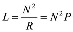
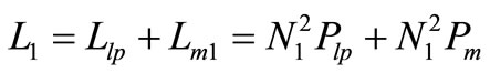
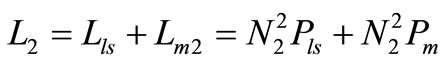
Based on the above relationships for the flux linkages, the primary and secondary inductances are also divided into two components (the leakage inductances and the magnetizing inductances) as following,
 (9)
(9)
 (10)
(10)
The mutual inductances as well are given as,
 (11)
(11)
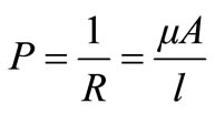
The above self-inductances plus the mutual inductance then are determined from modelling the physical structure of contactless transformers. The reluctance of each region of the structure is calculated from its area, length and permeability [Equation (12)], and inserted with its specific value into the appropriate location in the reluctance model, as shown in Figure 4. The magnetic field sources (ampere-turns) of the windings are assigned to any discrete point where the flux is not divided.
 (12)
(12)
The series reluctances for the same core section with the same dimensions can be summed giving the primary and secondary core reluctances as following,
 (13)
(13)
 (14)
(14)
Generally, the air gap reluctances are much greater than the adjacent ferrite core legs in Figure 4. This indicates the reluctance of the air-gap is governing and restrains the magnetic flux that is remaining through the core. Therefore, the core reluctances could be eliminated from the reluctance model. This leads to the simplified reluctance model as shown in Figure 5.
A dual now needs to be created for the magnetic circuit
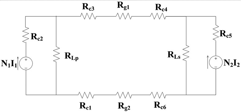
Figure 4. Reluctance model of the contactless transformer.
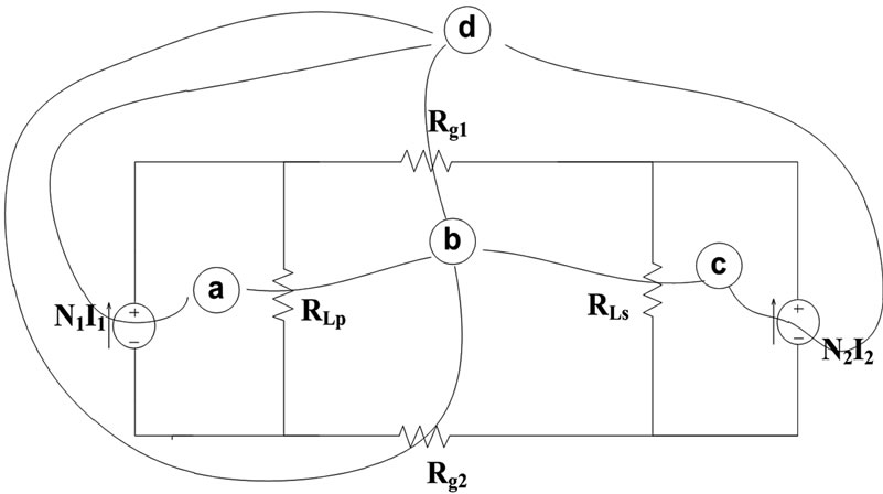
Figure 5. Simplified magnetic circuit.
of Figure 5 following the duality relationships between the two networks. For instance, in a reluctance model, nodes are the meshes in the electrical model. Similarly, open branch will be shorted, series will be parallel, mmf is a voltage source, and a reluctance is a permeance in the electrical network.
Figure 6 shows a permeance network of the reluctance model after applying a network transformation between the two networks. Permeance is the reciprocal of reluctance and can be calculated as follows,
 (15)
(15)
Next, the permeance model of Figure 6 is converted to inductance values by multiplying them with the respective number of turns squared  as a reference winding [Equation (16)]. Thus, terminal V1/N1 and V2/N2 are multiplied by N1 to become terminal voltage, and N1I1 and N2I2 are divided by N1 to become terminal current.
 (16)
(16)
Therefore, based on the above relationship, the primary leakage and magnetizing inductances of Equation (9) are given by,
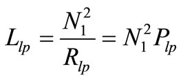 (17)
(17)
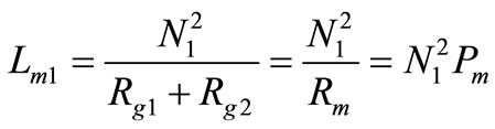 (18)
(18)
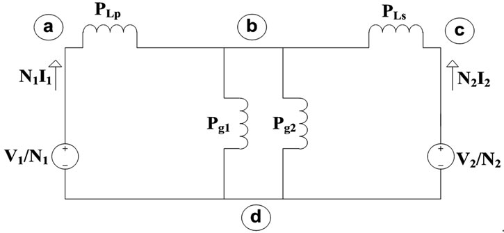
Figure 6. Permeance network.
Likewise, for the secondary side,
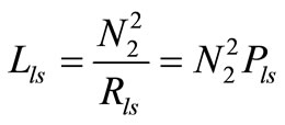 (19)
(19)
 (20)
(20)
Moreover, taking the ratio of Lm1 and Lm2 gives,
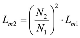 (21)
(21)
The primary and secondary inductances of Equations (9) and (10) then are given by,
 (22)
(22)
 (23)
(23)
The mutual inductance on the other hand depends on both windings and can be given as,
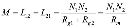 (24)
(24)
From Equations (18) and (24), the relationship between the mutual inductance and magnetizing inductance of the primary side can be obtained as following,
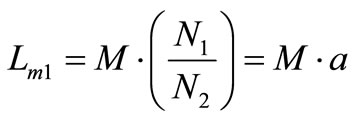 (25)
(25)
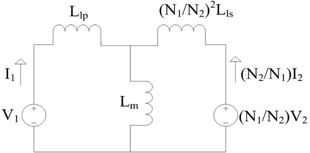
where , it is the turn’s ratio of the transformer. Using the above relationships leads to the inductance based electrical model of the transformer in Figure 7. It can be seen that the series reluctances of the air gaps show up as parallel inductances and the leakage inductances are in series. These parallel branches are the mutual inductance between the primary and secondary windings. It should be noted that the obtained secondary leakage inductance is the value seen from the primary side. It can be observed that the model of Figure 8(a) is the T-equivalent electrical circuit for the transformer seen from the primary side. To obtain the π-equivalent model an ideal transformer now needs to be added to allow different turn’s ratio. Thus, the final stage of transformation involves moving the secondary leakage induc-
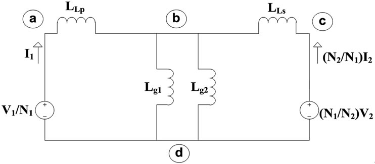
Figure 7. Inductance network.
 (a)
(a) (b)
(b)
Figure 8. (a) T-equivalent model; (b) π-equivalent model.
tance to the secondary side dividing by the square turn’s ratio. This leads to Figure 8(b) which is in consistent with the well-known π-equivalent model of a transformer.
The model presented in Figure 8(b), consists of the primary and secondary leakage inductances that represent the energy storage in the space around the windings and the magnetizing inductance that represents the energy storage in the magnetic core and the air-gap. The leakage inductance depends on the distance of the winding from the core. Unlike leakage, the magnetizing inductance is clearly dependent on the magnetic core and mainly the air-gap length.
It should be noted that for a contactless transformer used for contactless slipring systems, there is a complete circle of cores as it shown in Figure 9. Thus, the crosssection area for each flux path must be calculated for a circular path for the two different design structures in following sections.
4.1. Reluctance Calculations (Design 1)
Figure 10 shows the cross-section view of the coaxial design type contactless transformer. It is assumed that the shape of the primary and secondary cores is similar and the total shape has the circular symmetry. To calculate the mutual inductance, the air gap reluctances have to be
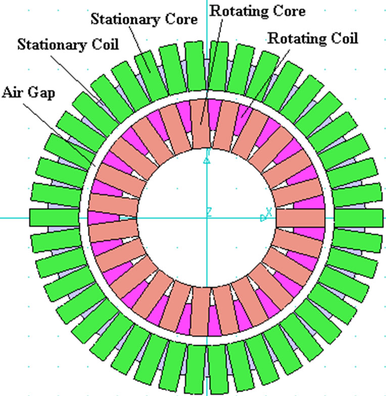
Figure 9. Complete geometry of a contactless transformer in CSS.
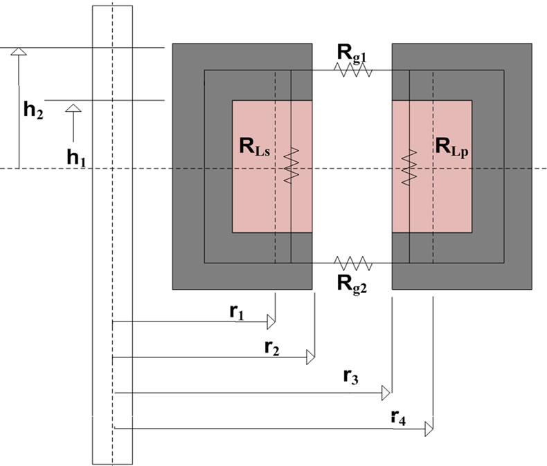
Figure 10. Cross-section view of a coaxial design.
obtained. As the air gap reluctances are horizontal in this design, their active cross-section areas for the magnetic flux flow can be calculated from Equation (26) for a cylindrical sector,
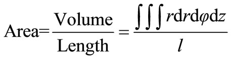 (26)
(26)
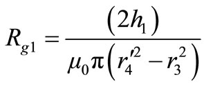
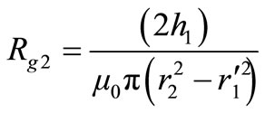
Therefore, for Rg1 and Rg2, the cross-section area for magnetic flux flow is,
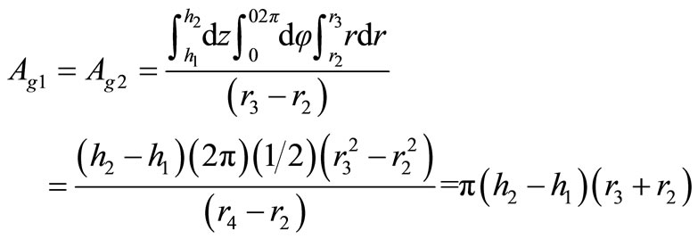 (27)
(27)
However, as presented earlier in Section 3, the effective gap area might be corrected to take the fringing field into account, thus the length of the air gap has to be added to the outer sides of the air gaps as following,
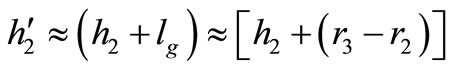 (28)
(28)
Thus the air gap reluctances are,
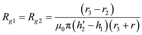 (29)
(29)
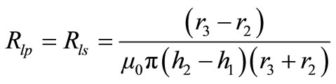
In case of the leakage inductances, practically, the major portion of the leakage flux start leaking when gets closer to the air gap after passing the first half of the core limb. This means, the second halves of the core limbs (“r2 – r1” for the secondary and “r4 – r3” for the primary in Figure 10) have to be considered for their cross-section area as follows,
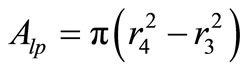 (30)
(30)
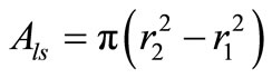 (31)
(31)
And for their relevant reluctances,
 (32)
(32)
 (33)
(33)
4.2. Reluctance Calculations (Design 2)
Similarly, for the second design shown in Figure 11 for the air gap reluctances, first the areas have to be corrected. Thus, for Rg1,
 (34)
(34)
And similarly for Rg2,
 (35)
(35)
 (36)
(36)
 (37)
(37)
Likewise, for the leakage flux lines, the second halves of the core limbs are considered for the flux flow. However, because they are horizontal in this design, the cross-section area for the flux flow is calculated from Equation (26), and accordingly the reluctances can be obtained from the following relationship,
 (38)
(38)
Table 1 summarises the derived equations for air gaps as well as leakage reluctances for both contactless trans-
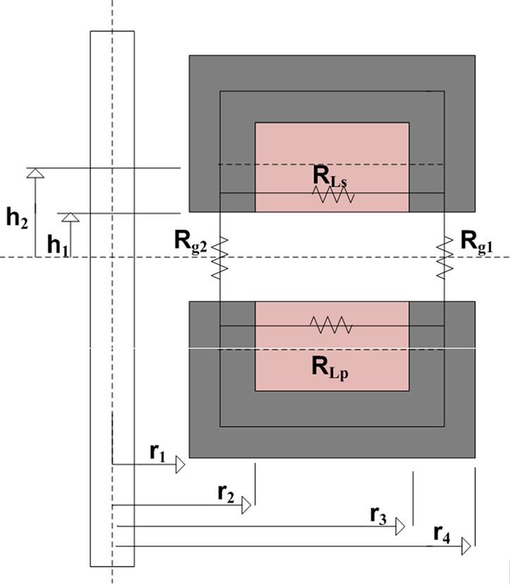
Figure 11. Cross-section view of a face to face design.
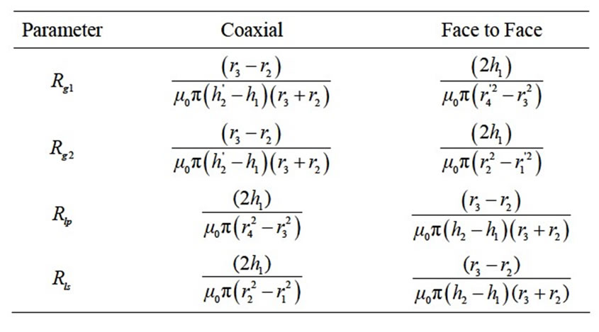
Table 1. Derived reluctance equations.
former designs. Using the derived equations of Table 1 the leakage inductances, mutual inductance, magnetizing inductance and the coupling coefficient of coaxial as well as face to face designs contactless transformers can be calculated before construction or performing any simulation work.
5. Accurate Modeling with Resistive Components
The windings losses in contactless transformer can be classified into two major groups: 1) the DC and 2) the AC losses. The DC losses are the result of current I (rms value of the current) flowing through the wire with resistance R, power (I2R) is dissipated and accordingly, developing heat on the wire. On the other hand, normally due to the varying magnetic field around the windings, the current distribution in the conductors is not uniform. The self-inductance of the conductor, as well as the magnetic field created by adjacent turns of the same winding, redistributes the current flow within the wire and reduces the effective cross-sectional area of the conductor and increase the AC resistance. These effects are known as skin and the proximity effects and become stronger at higher frequencies of operation [11]. The proximity effects together with the skin effect are the two high frequency effects that change the AC resistance of the conductors. Magnetic core losses are also exaggerated with higher frequencies, in turn, eddy currents and hysteresis effects becoming more severe.
As part of core losses, the enclosed area within the hysteresis loop is a measure of the energy lost in the core material during that cycle. This loss is made up in two components: 1) the hysteresis loss and 2) eddy current loss. The hysteresis loss is the energy loss when the magnetic material is going through a cycling state. The eddy current loss is caused when the lines of flux pass through the core, inducing electrical currents in it. These currents are the eddy currents and produce heat in the core. If the electrical resistance of the core is high, the current will be low; therefore, a feature of low-loss material is high electrical resistance. Normally, when designing magnetic coupling structure such as contactless transformer, the core loss is a major design factor. Core loss can be controlled by selecting the right material and thickness. Selecting the correct material, and operating within its limits, will prevent overheating that could result in damage to the wire insulation. The winding resistances Rw1 and Rw2 can be calculated using Cheng’s [12, 13] or Hurley’s [8,14] methods. Therefore, in this section only a new method of estimating the core losses in a contactless transformer is presented.
As obtained earlier, based on the calculated modelling derived from the physical layout, the T-equivalent circuit can be demonstrated as in Figure 12. The frequency domain relationships of this circuit can be given as,
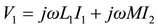 (39)
(39)
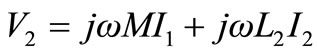 (40)
(40)
For the secondary side open-circuited (I2 = 0), the primary and the open circuit voltages are,
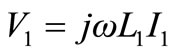 (41)
(41)
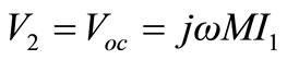 (42)
(42)
From Equations (25) and (42), the open circuit voltage in terms of magnetizing inductance can be written as,
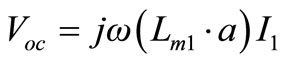 (43)
(43)
The open circuit voltage of Equation (43) across the magnetizing branch of the transformer is shown in Figure 13. Referring to the same figure, the primary voltage can be written as,
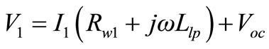 (44)
(44)
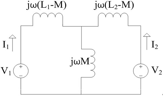
Figure 12. T-equivalent circuit.
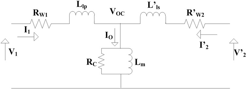
Figure 13. Equivalent circuit with magnetizing branch.
Combining Equations (43) and (44) gives the primary voltage as,
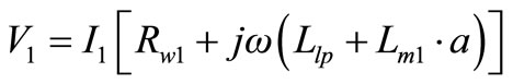 (45)
(45)
It should be noted that the total primary current in an unloaded transformer is the exciting current and establishes an alternating flux in the magnetic circuit. Thus, the primary current as an exciting current is calculated as,
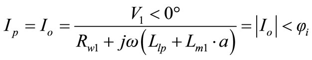 (46)
(46)
Where,
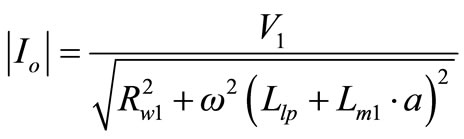 (47)
(47)
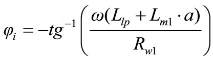 (48)
(48)
Since, magnetic flux in the core lags 90˚ behind the primary source voltage. The current drawn by the primary coil from the source to produce this flux is also lags the supply voltage by 90˚. Thereby, the exciting current comprises of two components, one is lagging by 90˚ and the other in phase (Figure 14). The in-phase component supplies the power absorbed by hysteresis and eddycurrent losses in the core. Where, the remainder is the magnetizing current as presented in below,
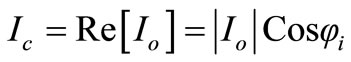 (49)
(49)
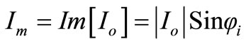 (50)
(50)
According to the two core loss and magnetizing components of the exciting current and their relevant impedances,
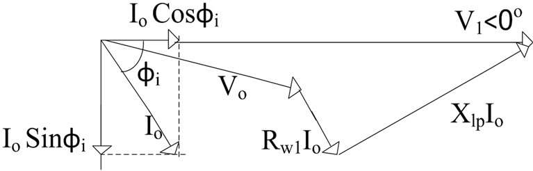
it can be written,
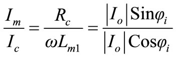 (51)
(51)
From the above relationship, core resistance then is,
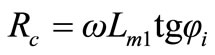 (52)
(52)
It can be observed that for minimizing the core losses, a core with high resistance is preferable. However, for ,
, , in turn the core losses are minimized. Nevertheless, because of the winding resistance,
  is always less than 90 in practice.
Equation (52) can be combined with Equation (48) giving the following relationship,
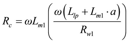 (53)
(53)
It should be noted that Equation (53) presents the core resistance irrelevant of current, voltage and phase angles and it is obtained based on the parameter values obtained from the physical dimensions for the given frequency. This is a strong and reliable tool for calculating the resistance representing the core loss with no need for any experimental or simulation works. Moreover, core resistance of Equation (53) is directly related to the quality factor of the primary winding at a certain frequency. Hence,
 (54)
(54)
Or at the resonant frequency (ω0 = 2πf0), can be related to the primary tuning capacitance by substituting (ω02L1 = 1/Cp) as,
 (55)
(55)
Equation (55) is important as it is a measure for primary tuning capacitor. Adding a capacitor in the primary side for the tuning purpose, the equivalent reactance and its compensating capacitance cancel each other out at the resonant frequency making winding resistance is the only remaining impedance. This will shift  to almost zero making
  maximum as presented in Equation (49). However, from Equation (50) as
  reduces, the magnetizing component of the exciting current is also reducing and according to that the conduction losses due to the circulating current (because of low magnetizing inductance for contactless transformer) is reduced.
Summing up, during designing a contactless slipring system, a good compromise between Rc and Cp has to be taken in consideration.
6. FEM Simulation
To verify the analytical method proposed in the previous section and compare the calculated electrical properties of the investigated transformers, finite element 3D simulation study has been performed. The software used for this purpose is the JMAG package. The magnetic 3D models are developed to calculate the mutual and leakage inductances and coupling coefficient. The solver of the package uses the “finite element method” as the analysis method. The FEM divides and expresses the analysis object into a finite number of elements, and each and every field of the element is calculated.The procedure is comprised of four basic stages: drawing the 2-D model, defining material properties and boundary conditions, create the 3-D model and simulating/post processing the results. The simulation is performed at 88 KHz operating frequency, N1 = N2 = 8, air gap of 3 mm, and ΔBmax = 0.3 Tesla. Results of the simulations are demonstrated in Table 2 in section-8 for comparison and further discussions.
7. Contactless Transformer Measurements
After a contactless transformer is built, measurements and tests can be conducted in order to verify its electrical characteristics. Contactless transformers are frequency sensitive and measurement conditions should match the operating conditions for accurate results.
The primary and secondary inductances can be measured from each side and leaving the other side open circuit (see Figure 15). Measuring the mutual inductance is different from the self-inductances, first the inductance of the primary and secondary measured in series, and then the connections of one winding for a second reading is interchanged as illustrated in Figure 16. The measured inductances are expressed as follows,
 (56)
(56)
 (57)
(57)
The mutual inductance then can be calculated applying the equation below,
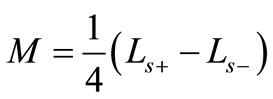 (58)
(58)
Using the values of the primary and secondary selfinductances and mutual inductance give the coupling coefficient as following,
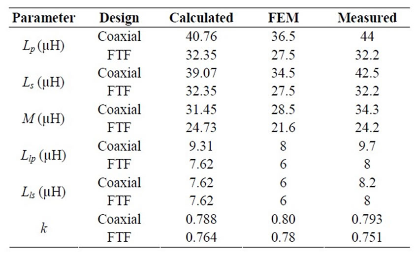
Table 2. Obtained results from different approaches.
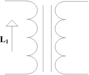
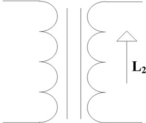
Figure 15. Primary and Secondary self-inductances measurements.
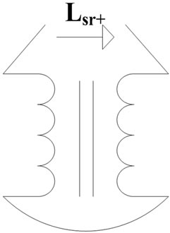
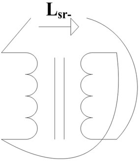
Figure 16. Mutual inductance measurement.
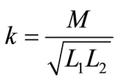 (59)
(59)
Obviously, what is not mutually coupled is the leakage; therefore the leakage inductance coefficient can be expressed as following,
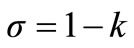 (60)
(60)
Likewise, the primary and secondary leakage inductances can be calculated from the following relationships,
 (61)
(61)
 (62)
(62)
It can be observed from Equations (61) and (62) that the coupling coefficient as well as the leakage inductance coefficient is independent of the transformer turns ratio. If the secondary is shorted, the resulting primary inductance (Lpss) is said to be given by,
 (63)
(63)
And the primary leakage inductance as,
 (64)
(64)
Note that Lpss is not the primary leakage inductance as sometimes claimed. The two Equations (63) and (64) give accurate results, if the following conditions hold; a) the transformer magnetizing inductance is much higher than the leakage inductances and b) the primary and secondary leakage inductances can be assumed to be equal. Clearly, in a contactless transformer neither of the above assumptions is valid. The magnetizing inductance is very low (and in some cases comparable to the leakage inductances) and therefore the secondary leakage cannot be combined with the primary leakage inductance. Also the primary and secondary leakage inductances are not always equal. Therefore, applying the first approach and using the Equation (56) to (62) give more accurate results.
8. Modeling Validation and Results Discussion
In order to verify the accuracy of the models obtained from the physical layout and the derived mathematical equations, two contactless transformers are built and their parameters are calculated by three different methods. Firstly, the parameters are calculated using the modeling procedure from the physical layout and relationships of Table 1. Secondly, using the same dimensions and calculating the parameters based on Finite Elements Method. Third method is based on measurements and practical experiments. For this purpose, the two designs are constructed and practical testing is performed.
Figure 17 illustrates the dimensions in “mm” of the investigated contactless transformers. Accordingly, Table 2 points up the results for the two axial types of the contactless transformers calculated by different approaches. It can be observed from the table that the calculated results have a good accuracy close to the measured results. Primary leakage inductance is higher in case of coaxial design and that is because of the greater cross section area and accordingly lower reluctance as compare to second design. However, this higher active cross section area is advantageous in order to achieve greater mutual inductance. It can be seen from the table that mutual inductance is higher for the case of coaxial design.
The leakage inductance is not determined by the air gap length and is only dependent on the distance windings from the core. Leakage inductance is directly related to the cross-section area of the windings from the core and inversely proportional to the distance between the limbs as shown in Figure 18. Therefore, to reduce the leakage inductance a long core with short limbs is preferable. Another way of reducing the leakage inductance by reducing its cross-section area for flux path is to have a thinner core. But, the disadvantage of this is reducing
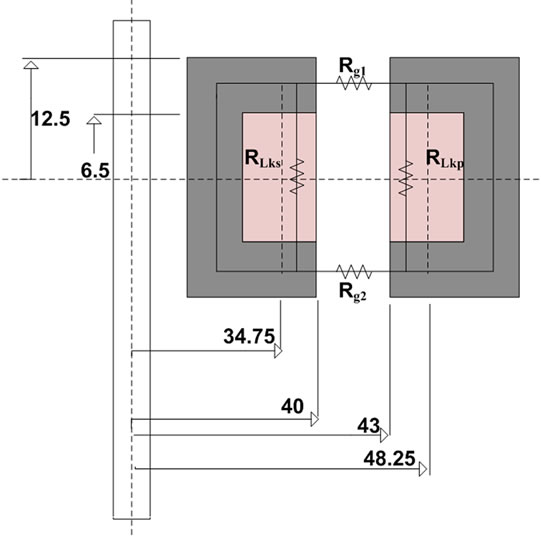 (a)
(a)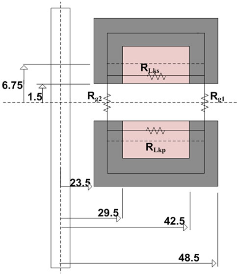 (b)
(b)
Figure 17. Dimensions of the prototyped designs (a) Coaxial; (b) Face to face.
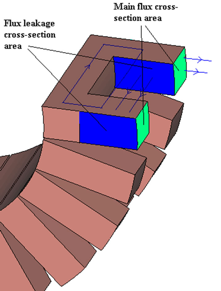
Figure 18. Cross-section areas of leakage and mutual inductances.
the cross-section area of the main mutual flux path, and accordingly reducing the mutual inductance.
On the other hand, the mutual inductance is mainly related to the air gap length and is increasing with the increase of the air gap. Moreover, a core with thicker limbs has the greater air gap area and accordingly will increase the mutual inductance. Accordingly, increasing the core area and keeping the air gap length results in higher coupling coefficient.
Moreover, a larger core window is usually required to fit the additional copper that handles the excess magnetizing current. To sum up, all are related to the application requirements and a good compromise should be taken between the size, output power, etc.
9. Conclusions
A method of obtaining an electrical network for modelling the physical structure of wind turbine contactless slipring system has been developed and verified. This is completed by full derivation of mathematical equations for numerical calculations.
Two axial designs; 1) coaxial and 2) face to face contactless transformers are modelled and their parameters are calculated based on the derived equations. This is followed by FEM simulation using JMAG software and experimental testing for modelling verifications.
It has been verified that the theoretical analysis is reliable and gives a good insight to the connection between the dimensions of the magnetic core, windings layouts and the resulting electrical characteristics. Furthermore, this helps the designer for better understanding the system before construction in order to modify and finalize the structure parameters. The calculated results have shown that the proposed method is accurate and trustworthy as compare to the FEM simulation and experimental results. Moreover, it has been found that correcting the effect of the air gap has a great influence on error reduction and obtaining an accurate value for the inductances.
It has been shown that leakage inductances are not dependent to the air gap length and only to the distance of the windings from the core and it can be reduced greatly by choosing an appropriate core for ex. Long core with short limbs. Besides, the mutual inductance is highly related to the air gap length and it can be increased by reducing the length of the air gap or increasing the air gap cross section area.
It has shown that resistance representing the core loss can be obtained based on the modelling from the physical structure at a given frequency. The effect of the primary tuning on the core loss is proven to be large thereby needs to be considered in designing contactless slipring system.
REFERENCES
- G. Gao and W. Chen, “Design Challenges of Wind Turbine Generators,” IEEE Electrical Insulation Conference, 31 May-3 June 2009, pp. 146-152. doi:10.1109/EIC.2009.5166334
- S. H. Marx, “A Kilowatt Rotary Power Transformer,” IEEE Transactions on Aerospace and Electronic Systems, Vol. AES-7, No. 6, 1971, pp. 1157-1163. doi:10.1109/TAES.1971.310219
- D. A. G. Pedder, et al., “A Contactless Electrical Energy Transmission System,” IEEE Transactions on Industrial Electronics, Vol. 46, No. 1, 2002, pp. 23-30. doi:10.1109/41.744372
- B. Potter and S. Shirsavar, “Design, Implementation and Characterisation of a Contactless Power Transfer System for Rotating Applications,” 32nd Annual Conference on IEEE Industrial Electronics, IECON 2006, 6-10 November 2006, pp. 2168-2173.
- A. P. Hu, “Selected Resonant Converters for IPT Power Supplies,” PhD Thesis, University of Auckland, Auckland, 2001.
- A. Abdolkhani and A. Hu, “A Sandwiched Magnetic Coupling Structure for Contactless Slipring Applications,” International Geoinformatics Research and Development, Vol. 2, No. 3, 2011, 8 Pages.
- A. Abdolkhani and A. P. Hu, “A Novel Detached Magnetic Coupling Structure for Contactless Power Transfer,” IECON 2011—37th Annual Conference on IEEE Industrial Electronics Society, Melbourne, 7-10 November 2011, pp. 1103-1108.
- K. D. Papastergiou and D. E. Macpherson, “An Airborne Radar Power Supply with Contactless Transfer of Energy— Part I: Rotating Transformer,” IEEE Transactions on Industrial Electronics, Vol. 54, No. 5, 2007, pp. 2874-2884. doi:10.1109/TIE.2007.902044
- C. W. T. McLyman, “Transformer and Inductor Design Handbook,” Vol. 121, CRC Press, New York, 2004. doi:10.1201/9780203913598
- E. C. Cherry, “The Duality between Interlinked Electric and Magnetic Circuits and the Formation of Transformer Equivalent Circuits,” Proceedings of the Physical Society. Section B, Vol. 62, No. 2, 1949, p. 101. doi:10.1088/0370-1301/62/2/303
- N. Mohan and T. M. Undeland, “Power Electronics: Converters, Applications, and Design,” Wiley, India, 2007.
- K. Cheng and P. Evans, “Calculation of Winding Losses in High Frequency Toroidal Inductors Using Multistrand Conductors,” IEE Proceedings of Electric Power Applications, Vol. 142, No. 5, 1995, pp. 313-322. doi:10.1049/ip-epa:19952041
- K. Cheng, “Computation of the AC Resistance of Multistranded Conductor Inductors with Multilayers for High Frequency Switching Converters,” IEEE Transactions on Magnetics, Vol. 36, No. 4, 2000, pp. 831-834. doi:10.1109/20.877573
- W. G. Hurley, et al., “Optimizing the ac Resistance of multilayer Transformer Windings with Arbitrary Current Waveforms,” IEEE Transactions on Power Electronics, Vol. 15, No. 2, 2000, pp. 369-376. doi:10.1109/63.838110