Engineering
Vol. 3 No. 12 (2011) , Article ID: 9207 , 10 pages DOI:10.4236/eng.2011.312147
The Bending of Rectangular Deep Beams with Fixed at Both Ends under Uniform Load
1Department of Civil Engineering and Mechanics, Yanshan University, Qinghuangdao, China
2Shenkan Qinghuangdao Engineering & Technology Corporation, Qinghuangdao, China
E-mail: cyjysu@126.com, {ldxg, baimingregan}@163.com, {907842492, 306532515}@qq.com
Received June 15, 2011; revised July 27, 2011; accepted August 9, 2011
Keywords: The Bending, Rectangular Section, Deep Beams, The Basic Solution, Uniform Load, Fixed at Both Ends, Reciprocal Method
ABSTRACT
Considering the effects of the beam section rotation, shear deformation of the adjacent section and transverse pressure, derived the new equation of rectangular section deep beams, and gives the basic solution of deep beams [1]. And discussed at the bending problems of deep rectangular beams with fixed at both ends under uniform load, based on the equations given in this paper, application of reciprocal law, doing numerical calculation in Matlab platform, compare with the results of ANSYS finite element analysis [2].
1. The Bending of Rectangular Deep Beams under Uniform Load
1.1. The Derivation of New Equations of the Rectangular Deep Beams
1.1.1. The Derivation of the Transverse Pressure 
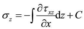
The elastic mechanics equations in z direction is
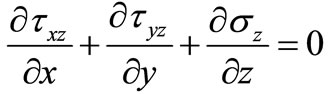 (1)
(1)
The  of straight beam which is in Figure 1 is 0, and then the Formula (1) change into
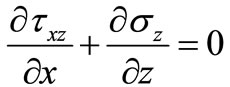 (2)
(2)
According to the material mechanics knowledge [3], there is
 (3)
(3)
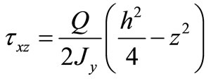
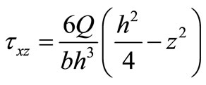
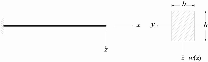
For the rectangular cross-section as shown in Figure 1, there is
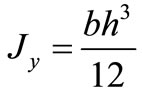 (4)
(4)
And then
 (5)
(5)
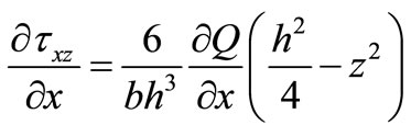
Calculating the Formula (2) to get
 (6)
(6)
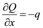
Paying attention to
 (7)
(7)
Due to
 (8)
(8)
 is the load strength of unit length along the
 direction.
Put Formulae (7) and (8) into (6) to get
 (9)
(9)
when
 (a)(b)
Figure 1. Straight beam of rectangular cross section.
 (10)
(10)
Reduction is
 (10)
(10)
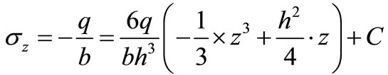
At last, getting:
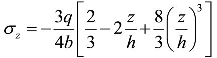 (11)
(11)
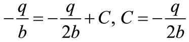
After calculation, we can get that when ,
, .
.
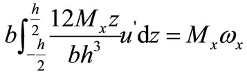
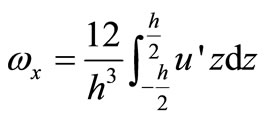
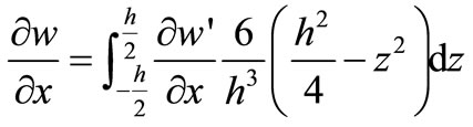
1.1.2. The Derivation of the Moment 
Introducing the concept of average corner . Making the
  is the average corner of cross section around
  axis, the
  is:
is:
 (12)
(12)
In the formula,  is the axial displacement of the straight beam. Because
 (13)
(13)
Put Formula (13) into (12) to get
There is
 (14)
(14)
Using the Hooke’s law to get
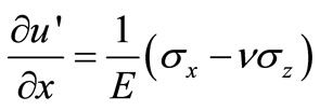 (15)
(15)
Put Formula (11) into (15) to get
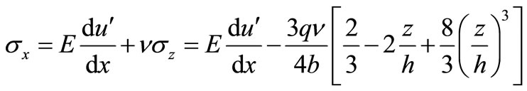 (16)
(16)
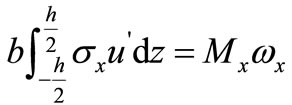
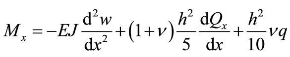
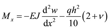
So the expression of the moment  is
is
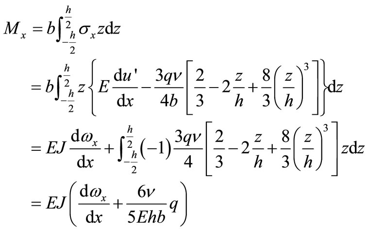 (17)
(17)
After this, we establish the relationships between  and
and 
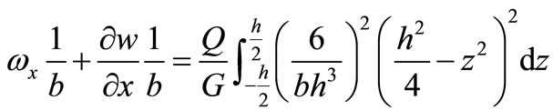
1.1.3. The Derivation of 
According to the shear hooker law [4], there is
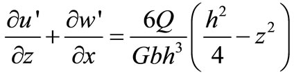 (18)
(18)
On both sides of Formula (18) are by , and doing definite integration between
  and
and  to get:
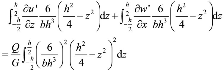 (19)
(19)
Calculating the first part of Formula (19) to get

The Formula (14) is paid attention to get
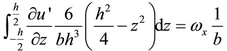 (20)
(20)
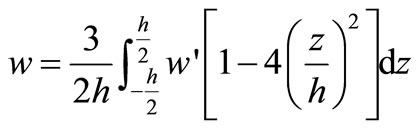
Introducing the concept of average deflection .
.  is the average deflection of various of points along the height of straight beam [5]. The
  is
is
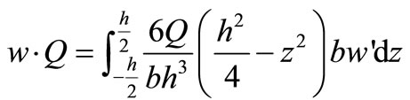
Calculating to get
 (21)
(21)
And then
 (22)
(22)
Putting Formulae (20) and (22) into (19) to get
 (23)
(23)
Given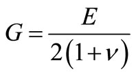 , after calculating to get
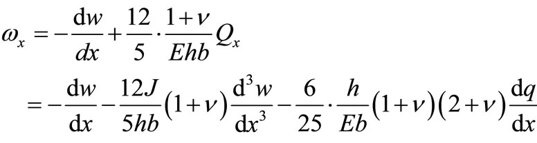
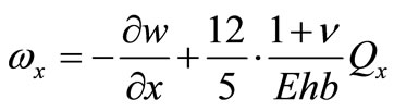 (24)
(24)
After this, we establish the relationships between ,
,  and
and .
.
1.1.4. The Establishment of Equilibrium Differential Equation
According to the material mechanics knowledge, there is
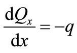 (25)
(25)
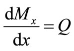 (26)
(26)
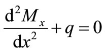 (27)
(27)
Putting Formula (25) into (28) to get
 (28)
(28)
Putting Formula (25) into (28) to get
 (29)
(29)
After this, we establish the relationships between  and
and .
.
Putting Formula (26) into (29) to get
 (30)
(30)
After this, we establish the relationships between  and
and .
.
Putting Formula (30) into (24) to get
 (31)
(31)
After this, we establish the relationships between  and
and .
.
Putting Formula (27) into (29) to get
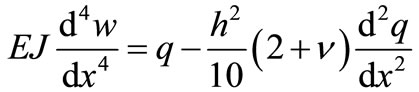 (32)
(32)
The Formula (32) is the equilibrium differential equation of the deep Beams under uniform load.
After that, the Formula (32) should be analyzed. Assuming that
 (33)
(33)
In the Formula (33),  is the uniform load and
  is the concentrated load of the point of
  which can be expressed as
 (34)
(34)
In the Formula (34),  is the one-dimensional Delta function of the point of
  and
and  is the concentrated couples of the point of
  which can be expressed as
 (35)
(35)
The control equation of the deep beams under uniform load , concentrated load
  and concentrated couples
  is
is
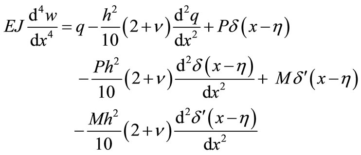 (36)
(36)
1.2. The Basic Solution of the Bending of Rectangular Deep Beams
Considering the boundary conditions of the deep rectangular beam as shown in Figure 2.
The deep rectangular beams as shown in Figure 3 with both ends simply supported under the one-dimensional Delta function 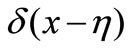 is considered as the basic system. The solution of the basic system is the basic solution of

Figure 2. Rectangular beam with different conditions.
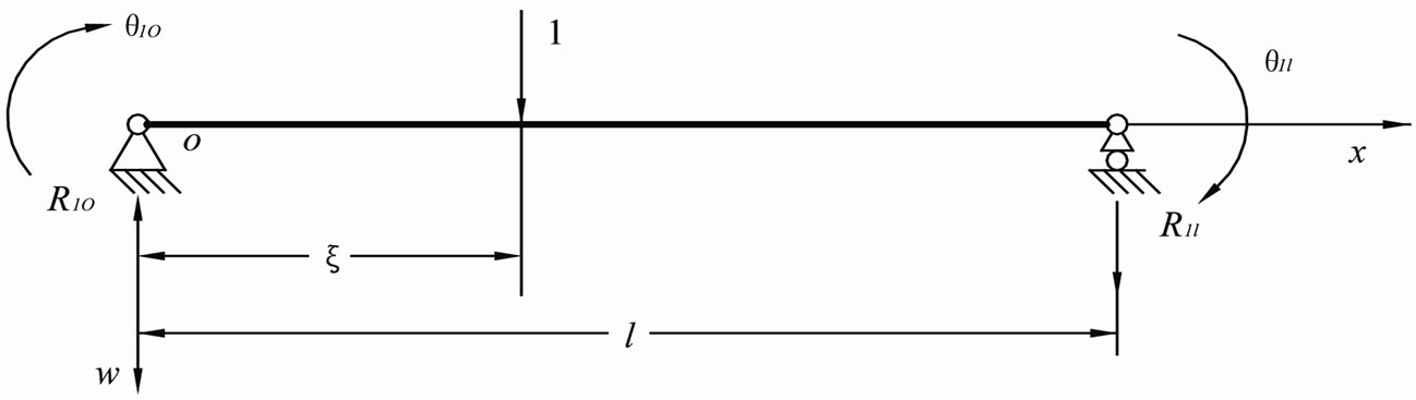
Figure 3. Fictitiously basic system for deep beams of the rectangular cross section.
deep beams. Theoretically, any straight beam under transverse uniform load  can be considered as the basic system, the solution of which can be considered as the actual system. However, the deep rectangular beams with both ends simply supported under transverse uniform load should be chosen as the basic system, for the solution of which is simple.
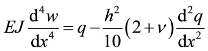
The control equation of the deflection functions is
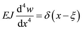 (37)
(37)
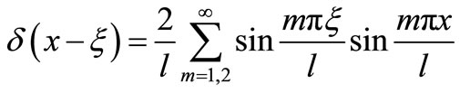
In the Formula (37),  is the one-dimensional Delta function of the point of
  which is
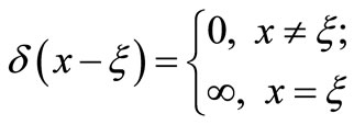
For any ,
,  which satisfy the condition of
  ,
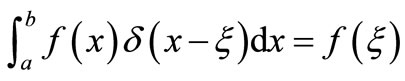
,  has the following properties
1) 
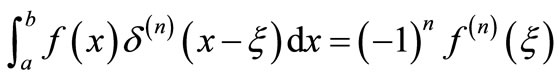
2) 
3) 
For the straight slender beam which is not considered the shearing deformation, in the Formula (37),  is the transverse unit concentrated load of the point of
 . However, for deep beams under the bending,
  is the one-dimensional Delta function of the point of
  which dose not have No mechanical significance is called unit concentrated load. And then the rectangular deep beam in Figure 3 is the basic system, the solution of which is the basic solution.
For the research, the function of  and its derivative of Fourier coefficient are provided in Table 1.
If  will be taken as single heavy trigonometric series, means that
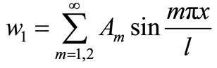 . And then
  will be spread out into a sine trigonometric series
 (38)
(38)
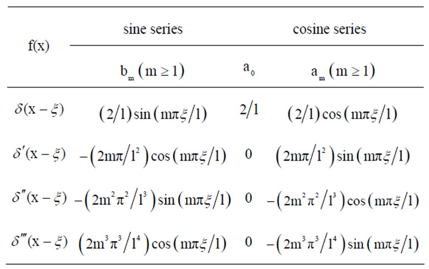
Table 1.  function and the fourier coefficients of its derivative with different orders.
Putting Formula (38) into (37) to get
 (39)
(39)
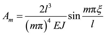
The basic solution can be got easily
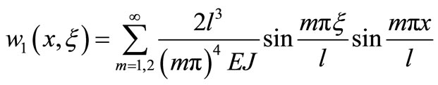 (40)
(40)
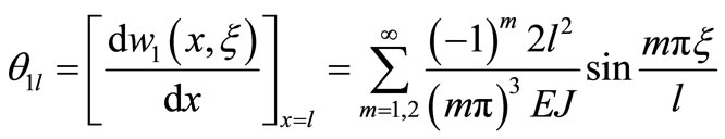
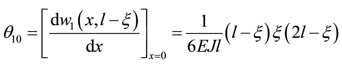
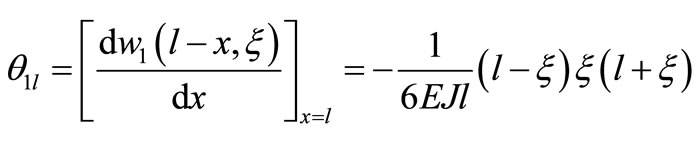
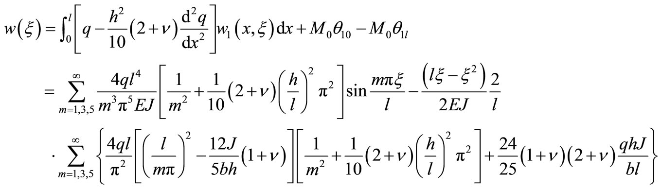
For calculating the flexible crankshaft equation of the actual system, boundary corner expression which is in the form of sine series of the actual system is provided as follow
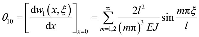 (41)
(41)
 (42)
(42)
And boundary corner expression which is in the form of polynomial of the actual system is provided as follow
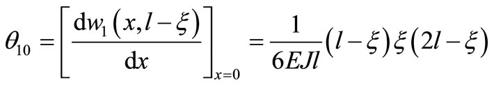 (43)
(43)
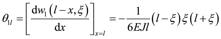 (44)
(44)
2. The Bending of Rectangular Deep Beams with Both Ends Simply Supported, Fixed at Both Ends under Uniform Load
2.1. The Bending of Rectangular Deep Beams with Both Ends Simply Supported
The actual system of rectangular deep beams with both ends simply supported, fixed at both ends under uniform load as shown in Figure 4.
The corresponding control equation is
 (45)
(45)
The basic system as shown in Figure 3, taking the left boundary corner with polynomial form as follow
 (46)
(46)
Taking the right boundary corner with polynomial form as follow
 (47)
(47)
Considering the reciprocal method between the basic system and the actual system (as shown in Figure 4), to get the buckling line equation of the actual system
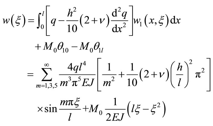 (48)
(48)
 is taken a derivatives for
  to get
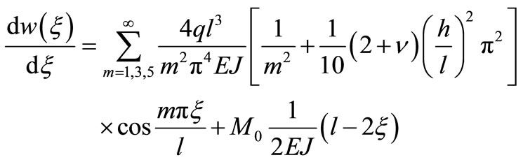 (49)
(49)
 is taken three derivatives for
  to get
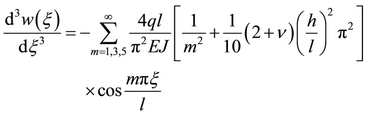 (50)
(50)
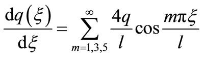 (51)
(51)
Putting Formulae (49)-(51) into (31) to get
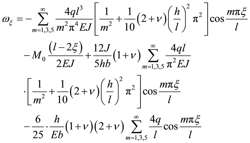 (52)
(52)
By the left of the beam boundary conditions to get the corner that should be 0, and then
 (53)
(53)
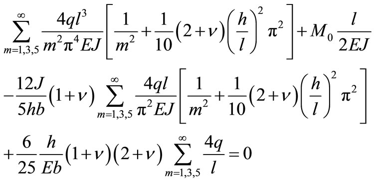
Solving to Formula (53) to get (54) )(see below).
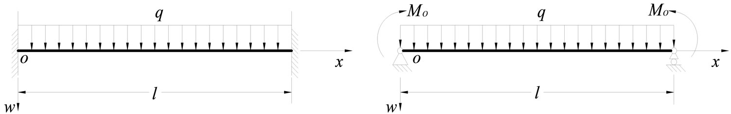 (a) (b)
Figure 4. Actual system of deep beams of the rectangular cross section with two edges fixed under uniformly distributed load.
![]()
![]()
 (54)
(54)
Putting Formula (54) into (48) to get (55) (see below).
2.2. Numerical Calculation
As a numerical calculation example, we make that the span of beam is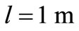 , the height of beam is
 , the width of beam is
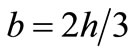 , depth-span ratio
  0.1, 0.2,…, 0.8, 0.9, Elastic modulus
 , Poisson’s ration is 0.3 to calculate the deflection value of beams with different depth-span ratio at various points along the y direction. In this example, the beam is divided into ten copies along the y direction (
 ), and there is the
 .
.
2.3. Finite Element Simulation
We use software of ANSYS Programming to calculate the deflection value of beams along the y direction. The deflection value of beams with different depth-span ratio at various points along the y direction is list in the Tables 3-5. Considering the symmetry of the boundary, the uniform loading across the entire span and the symmetry of deflection value of the beams, every table only list deflection value of half of the beam.
2.4. Analysis of the Results
The deflection value of beams with different depth-span ratio at various points along the y direction is list in the Tables 6-8.
The numerical solution and finite element calculation values of the deflection of beams with different depthspan ratio at various points of the 1/2 cross section are respectively list in the Tables 2 and 4. In this paper, the error between ANSYS finite element solution and the
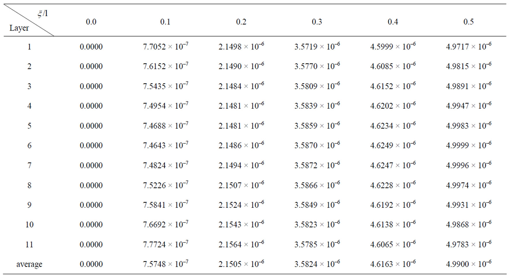
Table 2. Finite element deflection values at  of deep beam of
 .
.
![]()
![]()
 (55)
(55)
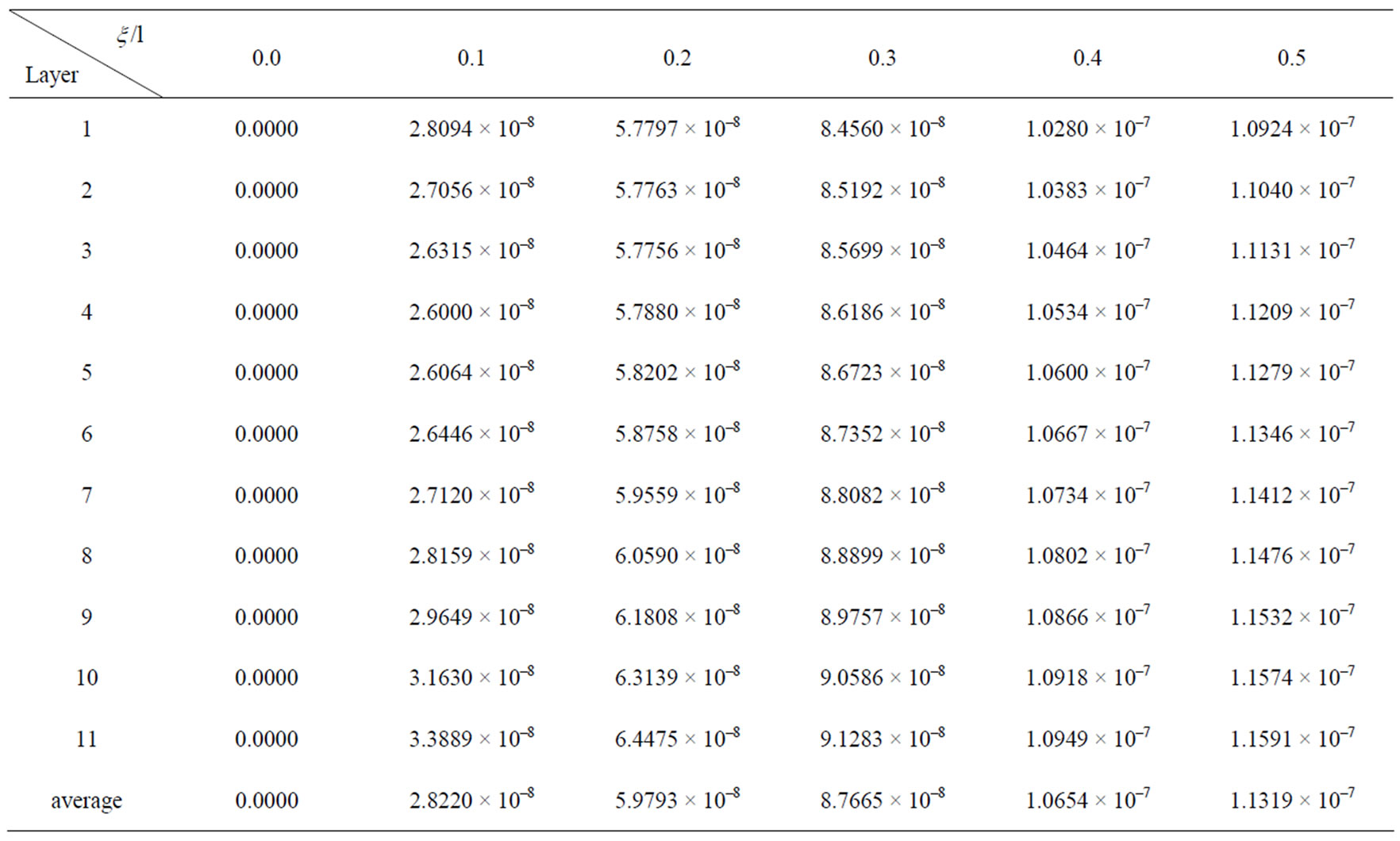
Table 3. Finite element deflection values at  of deep beam of
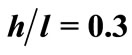 .
.
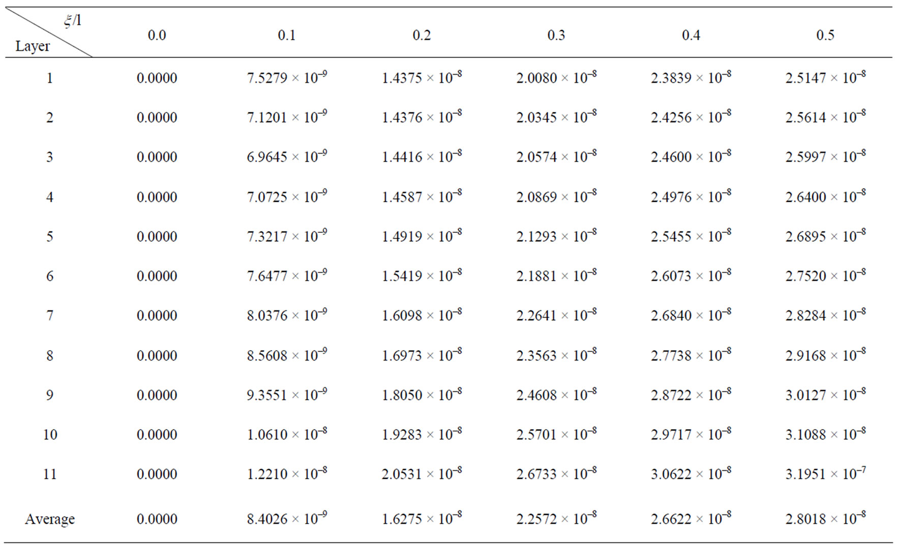
Table 4. Finite element deflection values at  of deep beam of
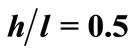 .
.
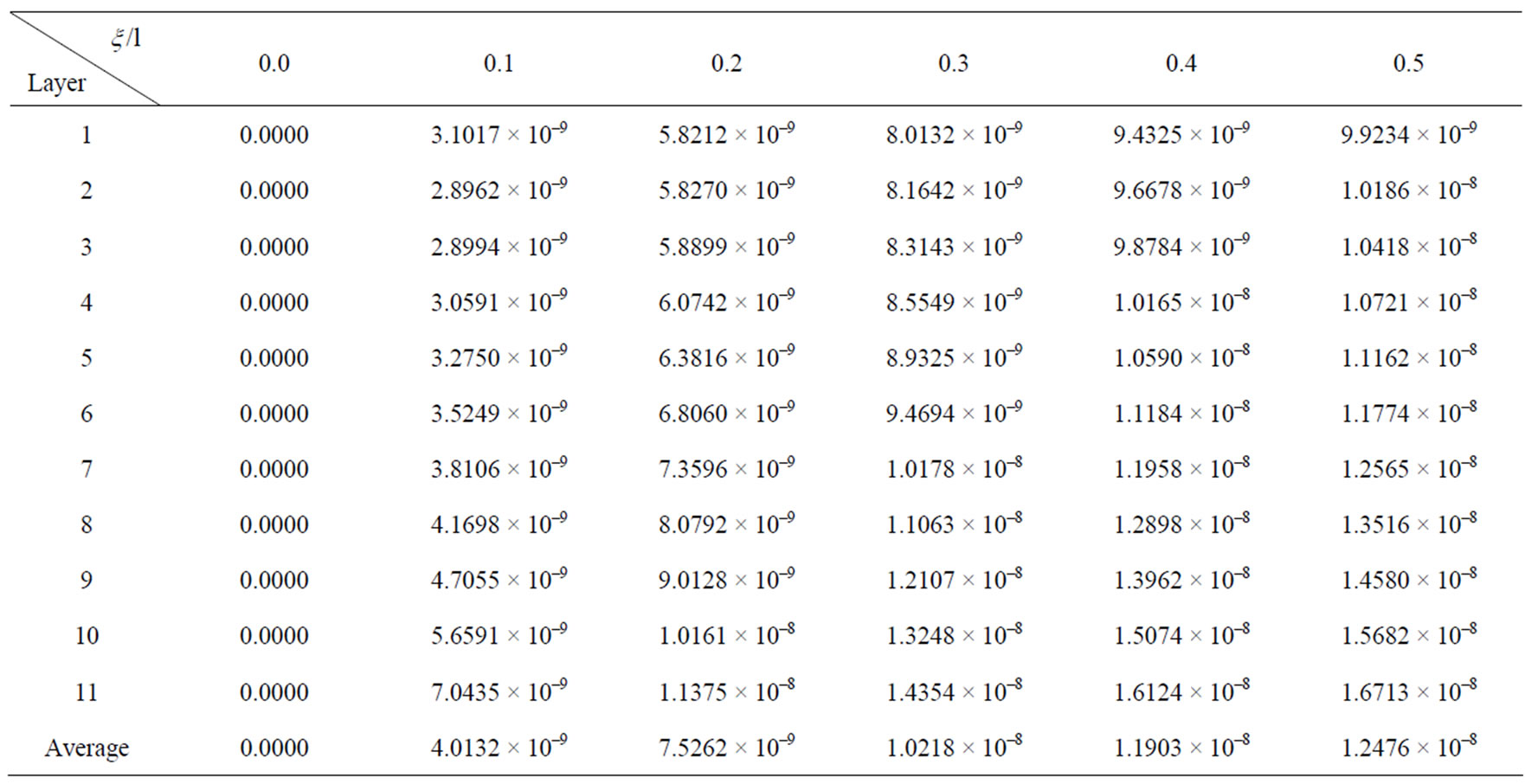
Table 5. Finite element deflection values at  of deep beam of
 .
.
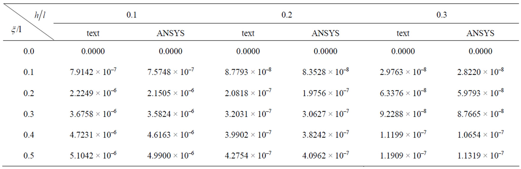
Table 6. Deflection values at .
.
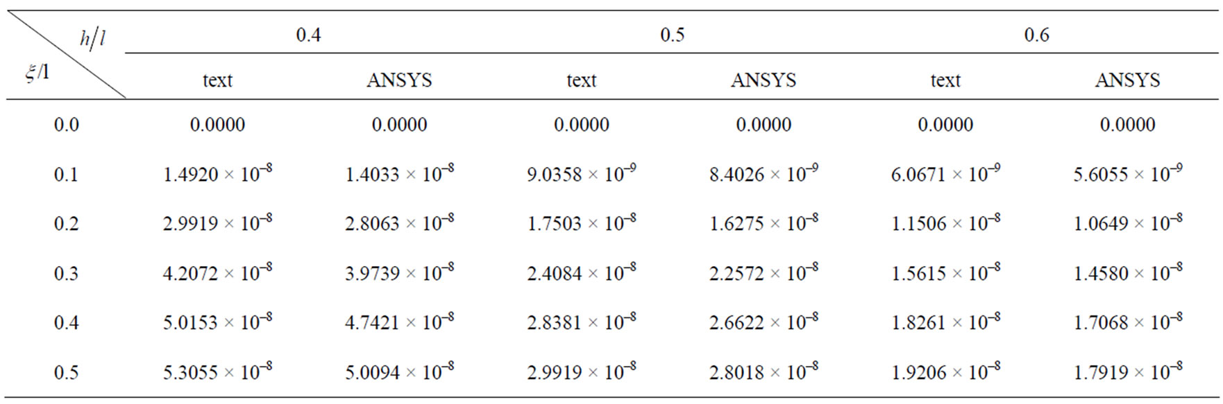
Table 7. Deflection values at .
.
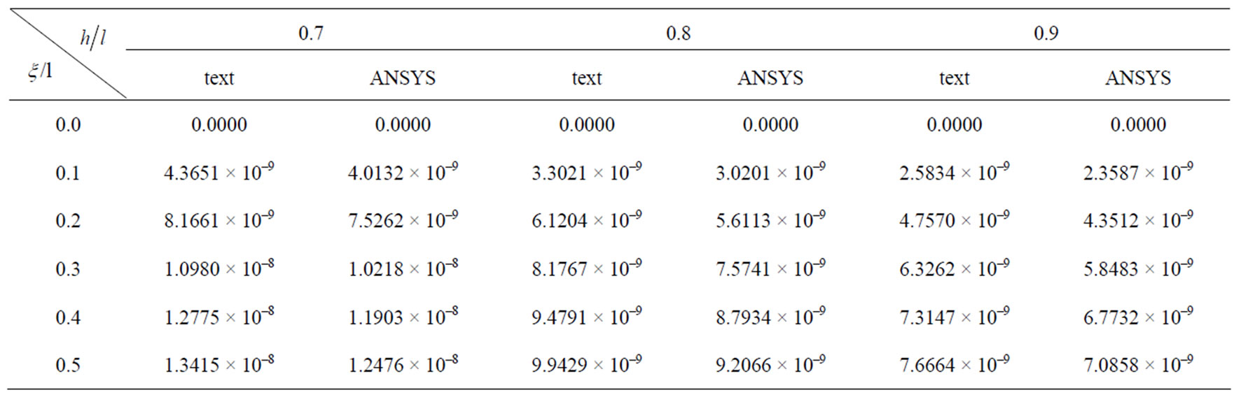
Table 8. Deflection values at .
.
 (a)
(a)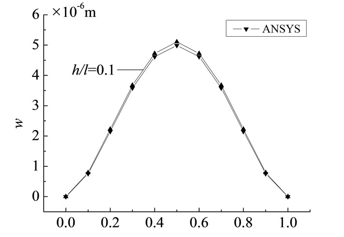 (b)
(b) (c)
(c)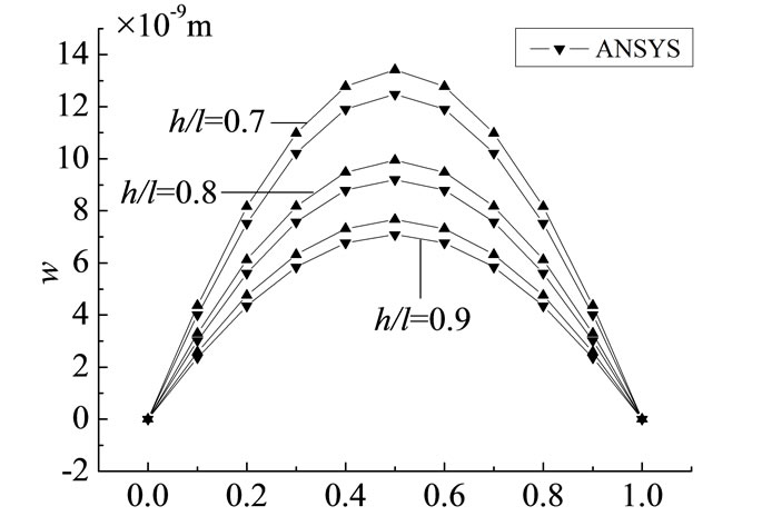 (d)
(d)
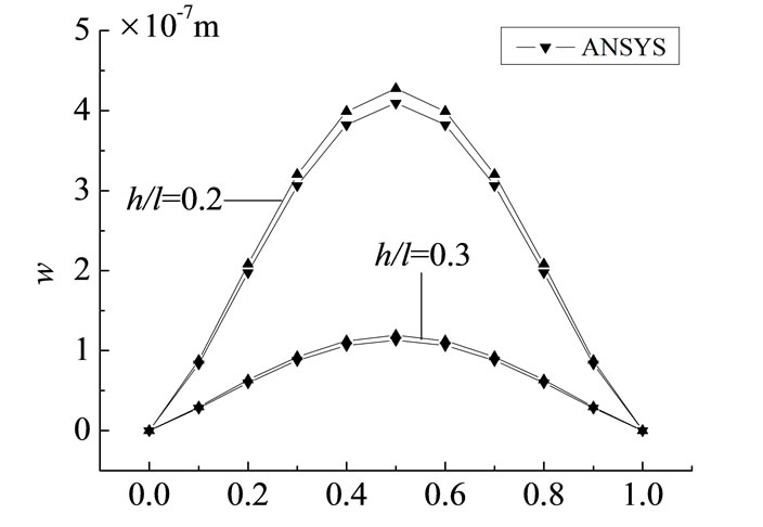
Figure 5. Deflection distribution curve at  with different depth-span ratios.
numerical solution respectively are 4.29%, 5.10%, 5.65%, 6.20%, 7.02%, 7.61%, 8.06%, 8.54%, 8.70%, all of which are in the range of allowable error. We can know the result is correct, and considering the reciprocal method to solve the problem is right.
The deflection distribution curve of beams with different depth-span ratio at various points along the y direction and the distribution curve of the finite element solution of the deep beam ( ) are respectively list in the Figure 5. Directly comparing with numerical results, and the two results can well fitting.
3. Conclusions
Considering the effects of the beam section rotation, shear deformation of the adjacent section and transverse pressure, derived the new equation of rectangular section deep beams, and gives the basic solution of deep beams. And we solve the example of the bending problems of deep rectangular beams with both ends simply supported, fixed at both ends under uniform load, based on the equations given in this paper, application of reciprocal law, doing numerical calculation in Matlab platform, compare with the results of ANSYS finite element analysis.
4. REFERENCES
- G. Q. Liu and K. Sun, “The Research of Concrete Deep Beams,” Technology Information, Vol. 3, 2008, pp. 88-89.
- X. Xu, “Consistent Variation from Levinson Theory to High Times Warp Beam Theory,” Engineering Mechanics, Vol. 25, No. 2, 2008, pp. 56-61.
- S. P. Timoshenko and J. M. Gere, “Strength of Materials,” Vannostrand Company, New York, 1972, pp. 45-63.
- R. D. Mindlin, “Influence of Rotary Inertia and Shear on Flexural Motions of Isotropic, Elastic Plates,” Journal of Applied Mechanics, Vol. 18, No. 1, 1951, pp. 31-38.
- G. R. Cowper, “The Shear Coefficient in Timoshenko’s Beam Theory,” Journal of Applied Mechanics, Vol. 33, No. 2, 1966, pp. 335-340. doi:10.1115/1.3625046