Intelligent Control and Automation
Vol.4 No.4(2013), Article ID:39504,6 pages DOI:10.4236/ica.2013.44045
Open-Loop Embedded Motion Control for Industrial Robots and CNC Machine Tools
1Department of Intelligent System Engineering, Graduate School of Dong-eui University, Busan, Korea
2Department of Mechatronics Engineering, Dong-eui University, Busan, Korea
Email: hoanggiap1005@gmail.com
Copyright © 2013 Nguyen Hoang Giap et al. This is an open access article distributed under the Creative Commons Attribution License, which permits unrestricted use, distribution, and reproduction in any medium, provided the original work is properly cited.
Received August 9, 2013; revised September 9, 2013; accepted September 16, 2013
Keywords: Motion Control; Industrial Robot; CNC Machine Tools
ABSTRACT
This paper presents the design and implementation of an embedded motion controller for industrial applications. The proposed control system has many advanced functions, including: high flexibility, high performance motion profile planning and multiple axis interpolation calculation. A high performance DSP and a FPGA chip are used for processing all demanded tasks in real-time.
1. Introduction
In the last few decades, motion control has developed steadily with the contribution of recent advanced control theories and technologies [1-4]. Along with the intensive applications of motion control, many works have been conducted to enhance the performance of the motion control system [5-7]. However, there have been few researches invested in both closed-loop and open-loop motion control. Moreover, most commercial controllers are of closed structure types, therefore it is difficult for users to develop or expand advanced functions [8]. The development of Field-Programmable Gate Array (FPGA) makes it easy to implement motion control application because of its simplicity and programmability, and parallel processing architecture [9-14]. However, FPGAbased controller is not flexible for designing an open structure of motion control system. Therefore, we attempt to develop an open structure and high performance embedded motion controller supported open-loop control by utilizing the powerful calculation of Digital Signal Processing (DSP) and real-time application of FPGA.
The proposed motion control system is designed with a DSP as the core microprocessor, which carries various functions required for open-loop motor control, such as interpolation, profile generation, PID control with feedforward and digital filters. For real-time multi-axis control, an FPGA is adopted to execute multi-channel feedback signal processing, universal inputs/outputs as well as output torque commands. A pulse generator module is also designed in the FPGA to generate multiple axis motion profile for open-loop type controller. The graphical user interface (GUI) is designed with Microsoft Visual C++ that gives comprehensive tools for user to select control modes and define motion trajectories.
This paper is organized as follows: Section 2 presents the design of motion control system, including hardware design and software design. Section 3 describes the design of interpolation algorithm and profile generation implemented in DSP part. Section 4 introduces the design of pulse generator module. The experimental results with various approaches are given in Section 5. Conclusions are drawn in Section 6.
2. Design of Motion Control System
2.1. System Hardware Design
The structure diagram of the multi-axis embedded motion system is shown in Figure 1. The proposed controller is developed based on a high performance DSP TMS320F2812, produced by TI and an FPGA XC3S1400A, produced by Xilinx. The DSP is responseble for calculating the interpolation, profile generation at the sampling time of 500 micro-second. The motion control system is connected to the PC through serial RS232 communication to analyze and monitor the working condition of the system. The FPGA is designed to process
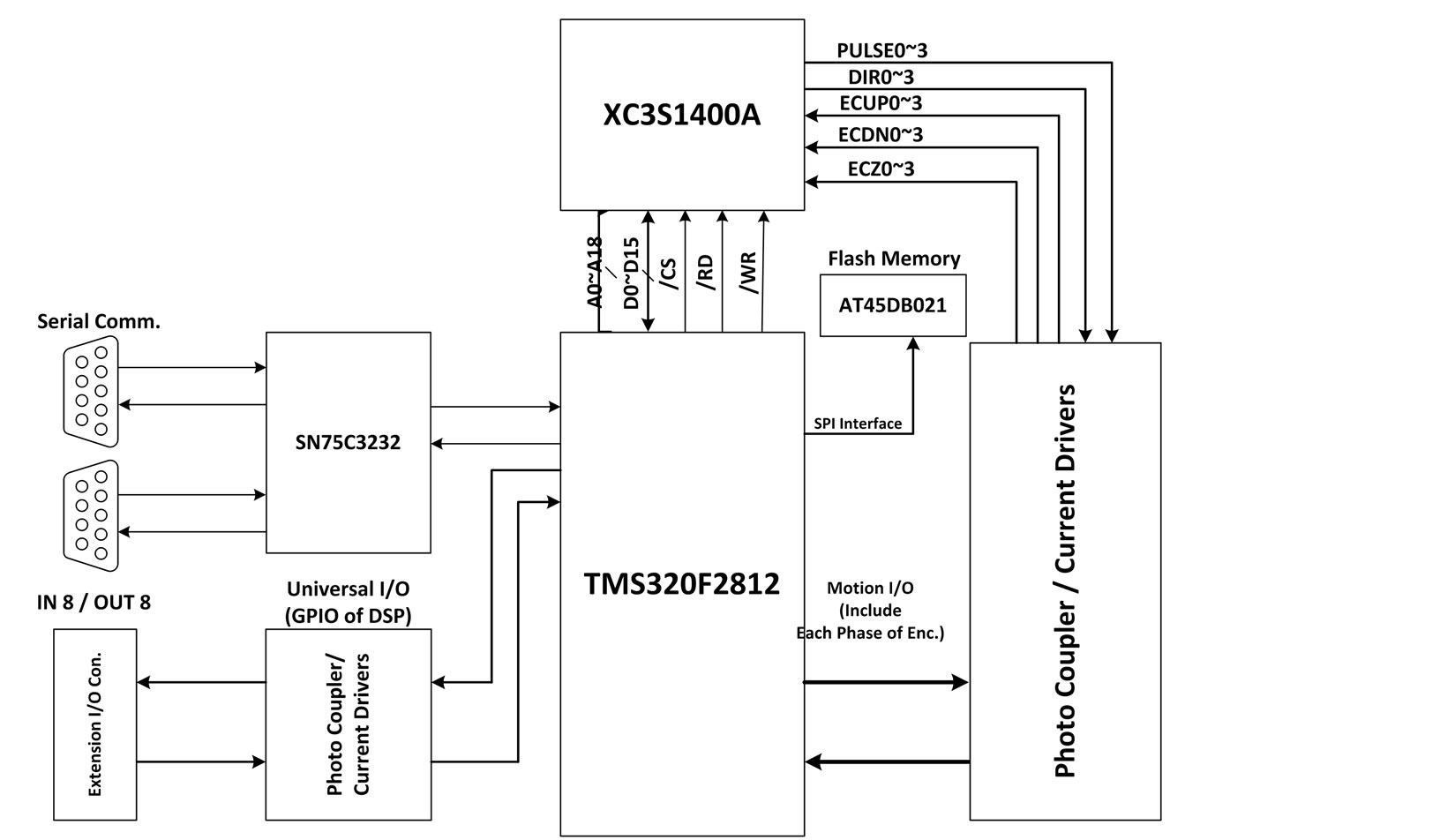
Figure 1. Hardware block-diagram of motion controller.
multi-channel encoder feedback signal and universal inputs/outputs at maximum rate of 4Mbps. Moreover, the FPGA is also used to decode the address bus and control bus of the whole system. Because the only SPI interface in the DSP is used to connect with the flash memory AT45DB021 for storing the control parameters.
The position and velocity data of each axis are calculated in the DSP, and sent to the FPGA. A pulse generation module designed in FPGA will calculate the pulse/ direction output from those data, and send to the line driver AM26LS31. Afterward, the differential signals output from the line driver are put to the servo driver pack to drive the motor.
The developed motion control board is showed in Figure 2.
The open structure of the proposed motion control system as showed in Figure 1 makes it easy and flexible for users to develop advanced motion algorithm.
2.2. System Software Design
Software design composes of computer level and microprocessor level. Computer level takes role of communicating with the motion control system to monitor, analyze and display the motion results. Computer software is developed under Microsoft Visual C++ environment, which is easy and flexible to design and integrate.
DSP firmware is carried out by C language in TI’s Code Composer V3.3 environment. The background loop of the program is used to receive the command data including position, velocity and acceleration/deceleration from the computer through RS232 communication. Then, the motion data will be analyzed and calculated as fol-
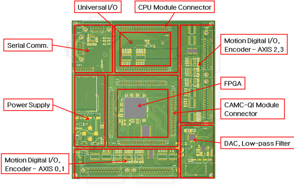
Figure 2. Developed motion control board.
lowing step: firstly, the data are checked whether they are valid or not; secondly, with valid data, interpolation calculation is performed to find the vector moving path, including path length and direction; thirdly, profile timing calculation is executed to calculate the moving time of each segment, and recalculate the motion command data, such as maximum velocity, command acceleration and deceleration; lastly, profile generation algorithm is used to produce the vector position and velocity of the path for each sampling time. In the timer interrupt routine, each vector position and velocity will be split into each single axis position and velocity.
3. Interpolation and Motion Profile Generation
Motion planning and interpolation play an important role in machine control. With the rapid development of microprocessor technology, motion control becomes easier and easier to employ. In this section, we will discuss about the simple and effective method to design a microprocessor-based motion planning module that can be utilized for open-loop application.
3.1. Interpolation Calculation
Generally, linear, circular and helical interpolations are among the basic techniques in trajectory planning which are applied widely in industrial manufacture.
Linear interpolant is a straight line between two given points  and
and . For a value
  in the interval
 , the value
  along the straight line is calculated from the following equation:
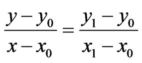 (1)
(1)
The design of linear interpolation function in microprocessor is straightforward. The displacement of linear trajectory can be calculated as following:
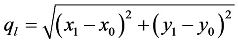 (2)
(2)
The computation of S-curve profile generation discussed in section B gives the position  and velocity
  of linear line in each sampling time. From these results, the position
  and velocity
  of single axis can be presented as following:
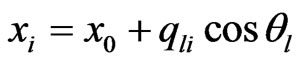 (3)
(3)
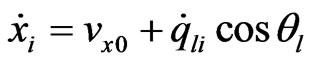 (4)
(4)
 (5)
(5)
 (6)
(6)
Circular interpolation or arc interpolation takes the center coordinates , start point
  and end point
 . The radius of circle is calculated as following:
 (7)
(7)
The displacement of the curve along two coordinates can be presented as:
 (8)
(8)
 (9)
(9)
where 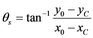
The displacement of the circle/arc is:
 (10)
(10)
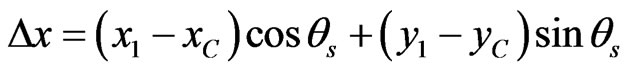
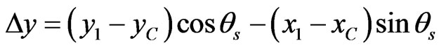
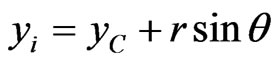
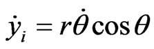
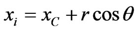
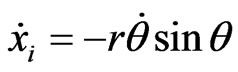
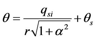
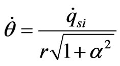
For a given set of position  and velocity
  of circular trajectory calculated from the profile generation process in section B, the position and velocity of single axis can be presented as following:
 (11)
(11)
 (12)
(12)
 (13)
(13)
 (14)
(14)
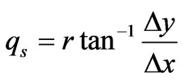
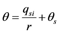
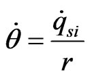
where  and
and  is displacement and angular velocity of circular trajectory, and can be obtained as following:
 (15)
(15)
 (16)
(16)
Helical interpolant is a three dimension trajectory composed of one circular and one linear move. For two given points ,
,  , and one center position
 , the displacement of helical trajectory can be presented as following:
 (17)
(17)
where  is the displacement of circular move calculated in (22).
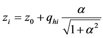
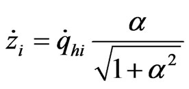
For a given set of position  and velocity
  of helical trajectory, the position and velocity of single axis can be obtained as following:
 (18)
(18)
 (19)
(19)
 (20)
(20)
 (21)
(21)
 (22)
(22)
 (23)
(23)
where  is the ratio of linear displacement and circular displacement.
The displacement  and angular velocity
  of circular trajectory, and can be presented as following:
 (24)
(24)
 (25)
(25)
3.2. Motion Profile Generation
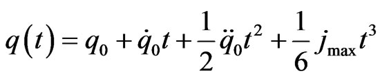
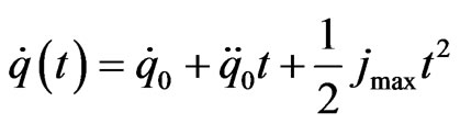
Motion profile planning is used to convert a desired motion to a stream of set points. The motion profile is usually expressed as a parametric function of time, which provides at each the corresponding desired position. S-curve trajectory or seven-segment trajectory is commonly used in motion control system to provide a smooth motion profile by adopting a continuous, linear piecewise acceleration profile. In this manner, the resulting velocity is composed by linear segment connected by parabolic blends. Since the jerk is characterized by a step profile, the stress load by this motion profile is reduced.
The seven main parts of S-curve profile can be presented as following:
1st, 3rd, 5th, and 7th segments:
 (26)
(26)
 (27)
(27)
 (28)
(28)
 (29)
(29)
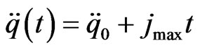
2nd, and 6th segments:
 (30)
(30)
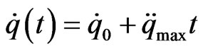 (31)
(31)
 (32)
(32)
 (33)
(33)
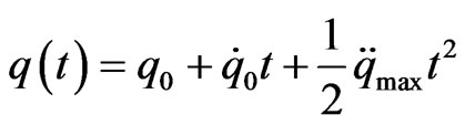
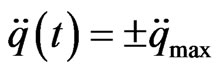
4th segments:
 (34)
(34)
 (35)
(35)
 (36)
(36)
 (37)
(37)
4. Design of Pulse Generator Module
Pulse generator module designed in FPGA can efficiently generate multiple axis motion profile for open-loop control. Figure 3 shows the architecture of the proposed pulse generator module. The CPU interface using Wishbone architecture is designed to communicate with the DSP part. At each sampling time, the calculated motion data including position data and velocity data from DSP are stored in data buffers and command pre-buffer for pulse generation process. The main controller calculates the position increment from the data received from buffers. The pulse and dir signal, represent the command pulse and direction of the motor, is generated by the pulse generator module. The busy signal indicates that motor is in motion. The comparator module compares the current command position with the predefine position in the trajectory in order to detect the specific command position on-the-fly.
5. Experimental Results
Based on the developed motion control system, we set up the experiment as shown in Figure 4. The motion board is connected to the Advantech IPC through RS232 communication. Four axes of the mechanical system are driven by four Panasonic servo motors. Each servo motor is driven by one analog amplifier, which is controlled by the motion board. The encoder of each motor has the resolution of 10,000 counts/revolution. The screw pitch of the lead screw is 10 mm. Therefore, one revolution of the motor is equivalent to 10 mm in linear move.
The experimental results of linear interpolation, circular interpolation and helical interpolation are shown from Figures 5-10 respectively. From the experimental results, it can be seen that the performance of developed motion control system meet the requirement of industrial robot control. The flexibility and the open design of the motion board make it easy to develop and configure advanced motion control algorithm.
6. Conclusions
In this paper, we introduced a low-cost multi-axis openloop type motion control. By utilizing the high performance and flexibility of the DSP, we develop a high performance motion control system which is applicable in
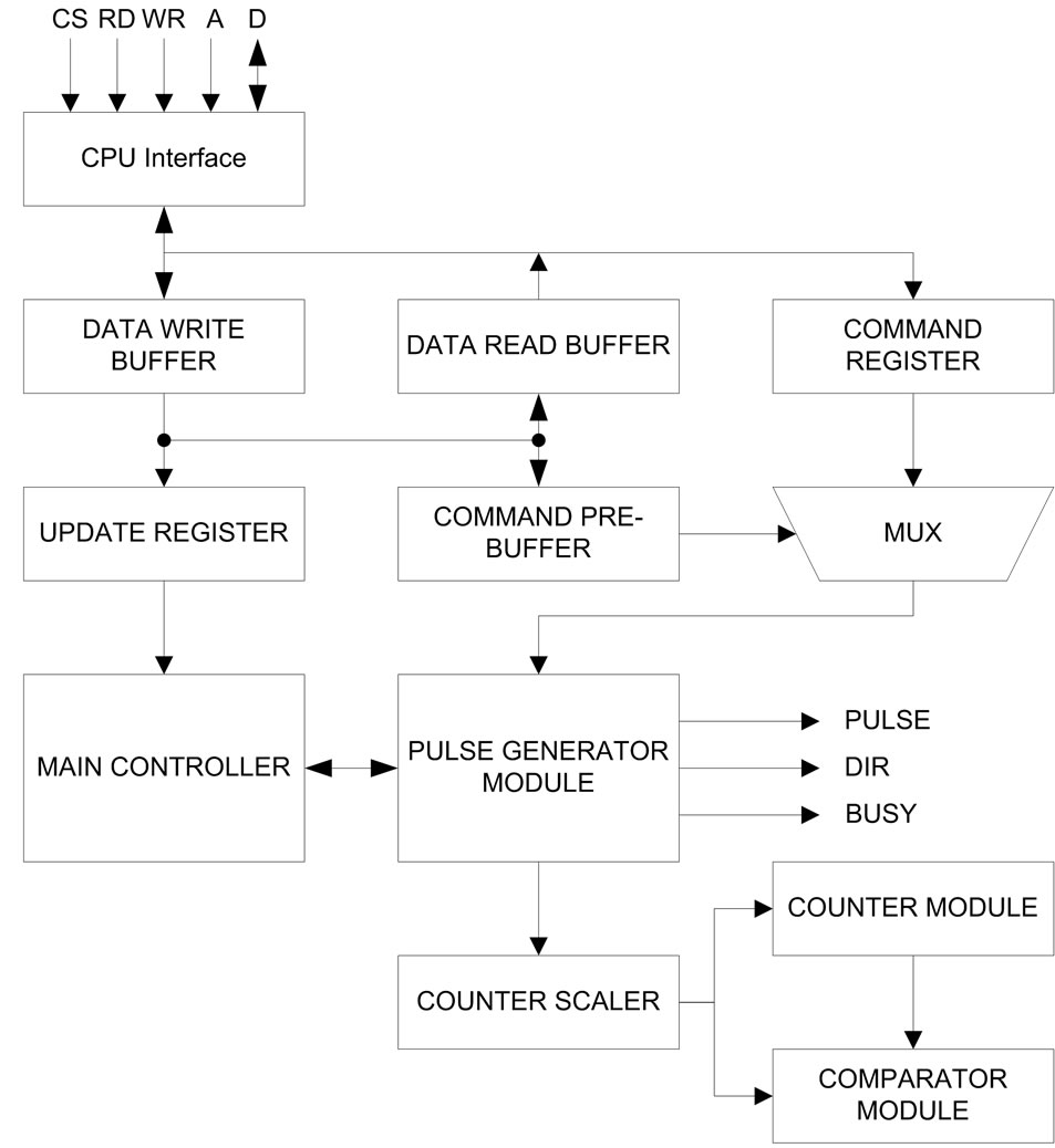
Figure 3. FPGA-based Pulse Generator Module.
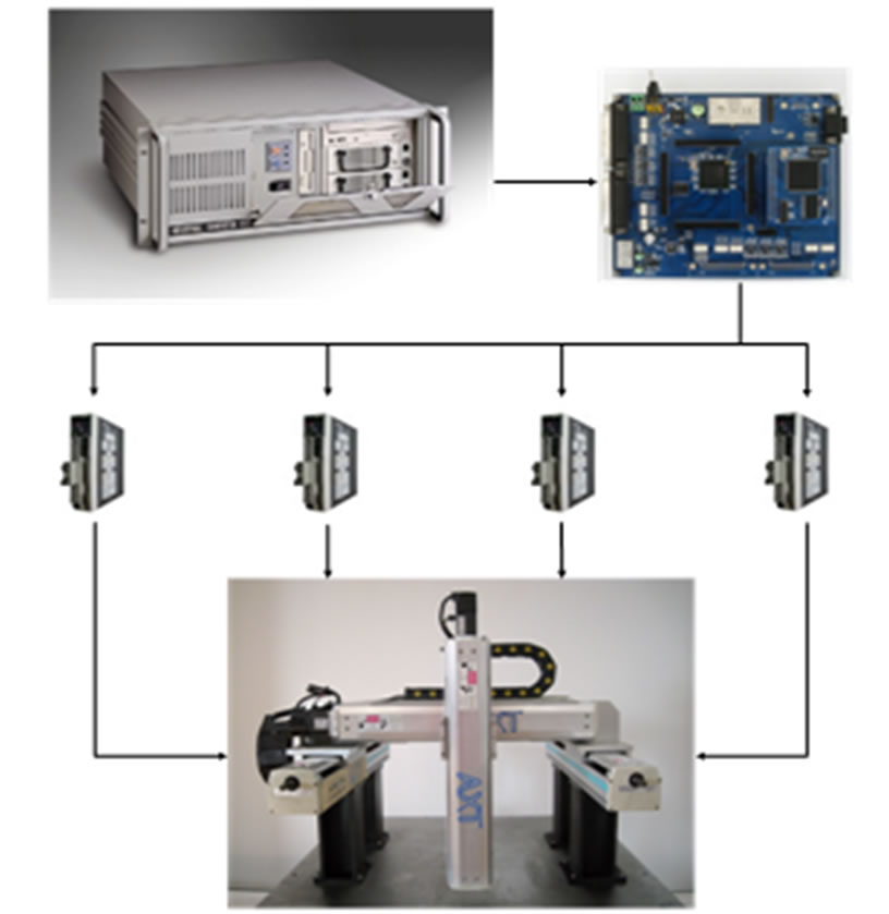
Figure 4. Experimental settings.
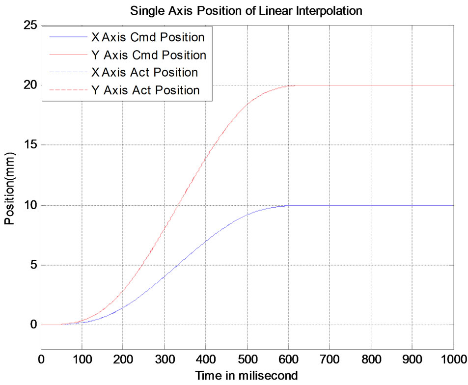
Figure 5. Single axis position of linear interpolation.
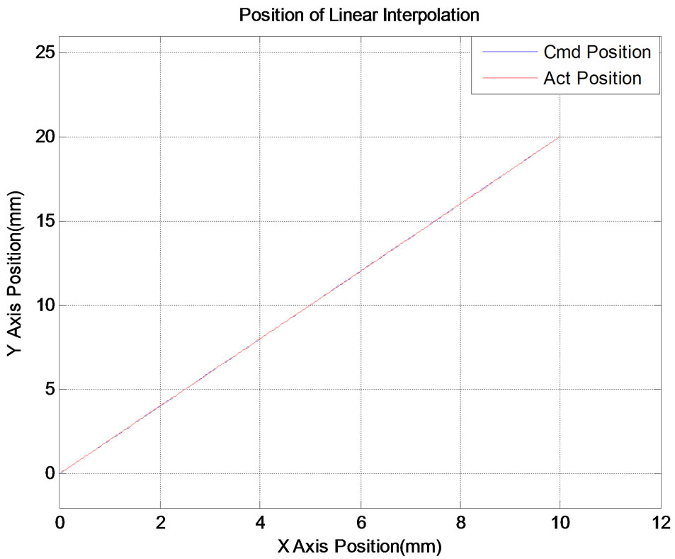
Figure 6. Position of linear interpolation.
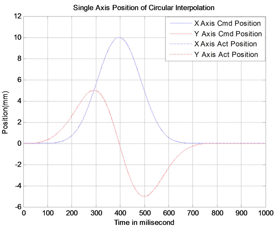
Figure 7. Single axis position of circular interpolation.

Figure 8. Position of circular interpolation.
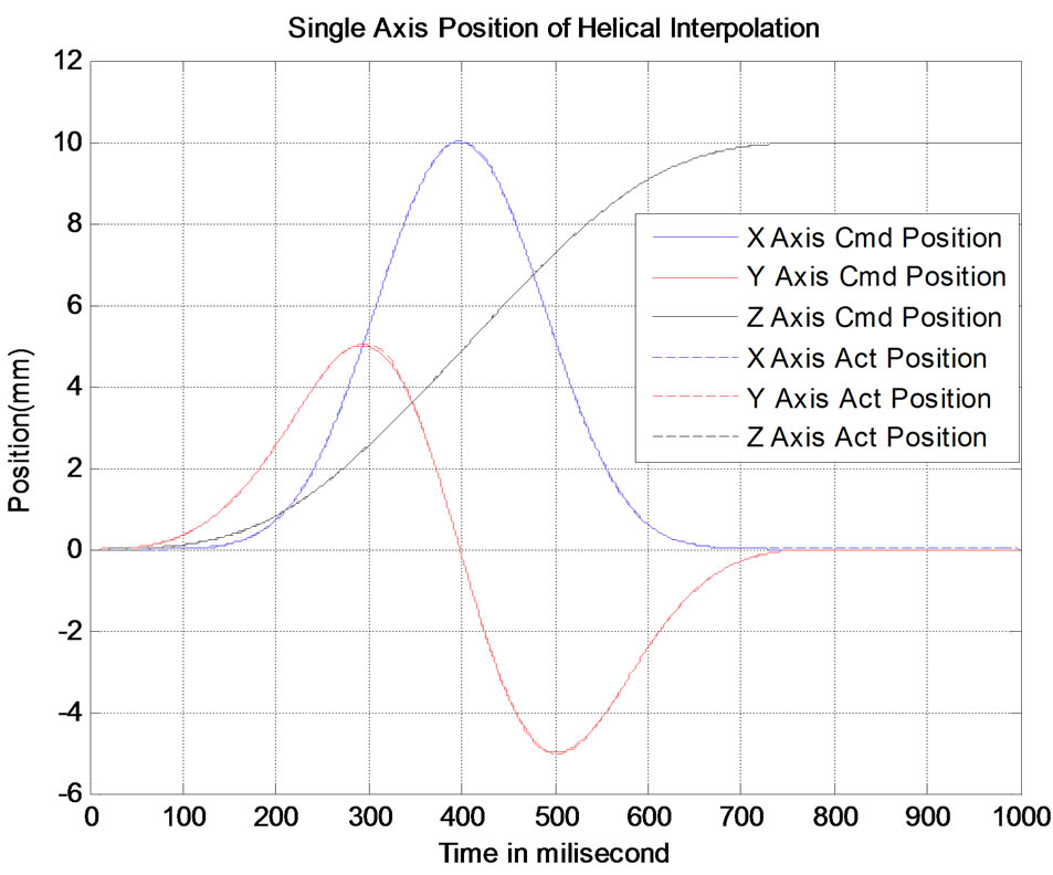
Figure 9. Single axis position of helical interpolation.

Figure 10. Position of helical interpolation.
high precision system such as CNC machine, planning machine, robot control. Moreover, the open-environment design helps users to adjust their advanced motion control algorithm easily.
For future works, some functions will be supplemented in the proposed motion controller such as motion blending function, inverse kinematic calculation, etc.
REFERENCES
- Y. X. Su, B. Y. Duan and Y. F. Zhang, “Robust Precision Motion Control for AC Servo System,” Proceedings of the 4th World Congress on Intelligent Control and Automation, Vol. 4, 2002, pp. 3319-3323.
- J. H. Kang, C. H. Yim and D. I. Kim, “Robust Position Control of AC Servo Motors,” Proceedings of the 1995 IEEE IECON, Vol. 1, 1995, pp. 621-626.
- H. W. Kim, J. W. Choi, S. K. Sul, “Accurate Position Control for AC Servo Motor Using Novel Speed Estimator,” Proceedings of the 1995 IEEE IECON, Vol. 1, 1995, pp. 627-632.
- M. Strefezza, H. Kobayashi, Y. F. Chen and Y. Dote, “Variable-Structure Robust Control by Fuzzy Logic and Stability Analysis for AC Drive System” 2nd IEEE Conference on Control Application, Vancouver, 13-16 September 1993, pp. 177-182. http://dx.doi.org/10.1109/CCA.1993.348285
- J. Chang, Y. Tan and J. T. Yu, “Backstepping Approach of Adaptive Control, Gain Selection and DSP Implementation for AC Servo System,” PESC 2007, June 2007, pp. 535-541.
- L. Wang, Y. S. Xiao, Q. D. Wu and G. X. Zhou, “Neural Network Based Parameters Identification and Adaptive Speed Control of AC Drive System,” Proceedings of the IEEE International Conference in Industrial Technology, Shanghai, 2-6 December 1996, pp. 118-121. http://dx.doi.org/10.1109/ICIT.1996.601553
- J. U. Cho, Q. L. Ngoc and J. W. Jeon, “An FPGA-Based Multiple-Axis Motion Control Chip,” IEEE Transactions on Industrial Electronics, Vol. 56, No. 3, 2009, pp. 856- 870. http://dx.doi.org/10.1109/TIE.2008.2004671
- M. W. Naouar, E. Monmasson, A. A. Naassani, I. S. Belkhodja and N. Patin, “FPGA-Based Current Controllers for AC Machine Drives-A Review,” IEEE Transactions on Industrial Electronics, Vol. 54, No. 4, 2007, pp. 1907-1925. http://dx.doi.org/10.1109/TIE.2007.898302
- L. Desborough, R. Miller, “Increasing Customer Value of Industrial Control Performance Monitoring-Honeywell Experience,” 6th International Conference Chemical Process Control, AIChE Symposium Series 326, AIChE, New York, 2002.
- B. You, D. Li and S. Liu, “Design of DSP-Based Open Control System for Industrial Robot,” Proceedings of the IEEE International Conference on Automation and Logistics, Jinan, 18-21 August 2007, pp. 1585-1590.
- R. Volpe, “Task Space Velocity Blending for Real-Time Trajectory Generation”, Proceedings IEEE International Conference on Robotics and Automation, Atlanta, 2-6 May 1993, pp. 680-687. http://dx.doi.org/10.1109/ROBOT.1993.291880
- Y. S. Kung, K. H. Tseng and T. Y. Tai, “FPGA-Based Servo Control IC for X-Y Table,” Proceedings of IEEE International Conference on Industrial Technology, Mumba, 15-17 December 2006, pp. 2913-2918.
- X. Shao, D. Shun and J. K. Mills, “A New Motion Control Hardware Architecture with FPGA-Based IC Design for Robotic Manipulators,” Proceedings of IEEE International Conference on Robotics and Automation, Orlando, 15-19 May 2006, pp. 3520-3525.
- Y. F. Chan, M. Moallem and W. Wang, “Design and Implementation of Modular FPGA-Based PID Controller,” IEEE Transactions on Industrial Electronics, Vol. 54, No. 4, 2007, pp.1898-1906.