Intelligent Control and Automation
Vol. 3 No. 3 (2012) , Article ID: 22049 , 8 pages DOI:10.4236/ica.2012.33028
Artificial Intelligence Application’s for 4WD Electric Vehicle Control System
Faculty of Sciences and Technology, Bechar University, Bechar, Algeria
Email: nasriab1978@yahoo.fr
Received February 26, 2012; revised June 18, 2012; accepted June 25, 2012
Keywords: 4WD; PI; Adaptive Fuzzy PI; Fuzzy Controller; Direct Torque Control.SOC
ABSTRACT
A novel speed control design of 4WD electric vehicle (EV) to improve the comportment and stability under different road constraints condition is presented in this paper. The control circuit using intelligent adaptive fuzzy PI controller is proposed. Parameters which guide the functioning of PI controller are dynamically adjusted with the assistance of fuzzy control. The 4WD is powered by four motors of 15 kilowatts each one, delivering a 384 N.m total torque. Its high torque (338 N.m) is instantly available to ensure responsive acceleration performance in built-up areas. The electric drive canister of tow directing wheels and tow rear propulsion wheels equipped with tow induction motors thanks to their light weight simplicity and their height performance. Acceleration and steering are ensure by electronic differential, the latter control separately deriving wheels to turn at any curve. Electric vehicle are submitted different constraint of road using direct torque control. Electric vehicle are simulated in Matlab Simulink. The simulation results have proved that the intelligent fuzzy PI control method decreases the transient oscillations and assure efficiency comportment in all topologies road constraints, straight, curved road, descent.
1. Introduction
The principal constraints in vehicle design for transportation are the development of a non-polluting high safety and comfortable vehicle. Taking into account these constraints, our interest has been focused on the 4WD electrical vehicle, with independent driving wheel-motor at the front and with classical motors on the rear drive shaft [1-4]. This configuration is a conceivable solution, the pollution of this vehicle is strongly decreased and electric traction gives the possibility to achieve accurate and quick control of the distribution torque. Torque control can be ensured by the inverter, so this vehicle does not require a mechanical differential gear or gearbox. One of the main issues in the design of this vehicle (without mechanical differential) is to assume the car stability. During normal driving condition, all drive wheel system requires a symmetrical distribution of torque in the both sides. In recent years, due to problems like the energy crisis and environmental pollution, the Electric Vehicle (EV) has been researched and developed more and more extensively [1,2]. Currently, most EVs are driven by two front wheels or two rear wheels. Considering some efficiency and space restrictions on the vehicle, people have paid more and more attention in recent years to fourwheel drive vehicles employing the IM in-wheel motor.
Research has shown that EV control methods such as, PI control are able to perform optimally over the full range of operation conditions and disturbances and it is very effective with constant vehicle torque, Moreover these non-linear vehicle torque are not fixed and change randomly. However EV with conventional PI control may not have satisfactory performance in such fast varying conditions, the system performance deteriorates. In addition to this, it is difficult to select suitable control parameters Kp and Ki in order to achieve satisfactory compensation results while maintaining the stability of EV traction, due to the highly complex, non-linear nature of controlled systems. These are two of the major drawbacks of the PI control. In order to overcome these difficulties, adaptive PI controller by fuzzy control has been applied both in stationary and under roads constraints, and is shown to improve the overall performance of 4WD electric vehicle.
The aim of this paper is to understand the impact of intelligent fuzzy speed controller using lithium-ion battery controlled by DC-DC converter, each wheels is controlled independently by via direct torque control based space vector modulation under several topologies. Modelling and simulation are approved out using the Matlab/Simulink tool to study the performance of 4WD proposed system.
2. Electric Vehicle Description
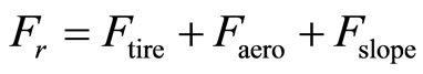
According to Figure 1 the opposition forces acting to the vehicle motion are: the rolling resistance force  due to the friction of the vehicle tires on the road; the aerodynamic drag force
 ![]() caused by the friction on the body moving through the air; and the climbing force
caused by the friction on the body moving through the air; and the climbing force  that depends on the road slope.
The total resistive force is equal to  and is the sum of the resistance forces, as in (1).
 (1)
(1)
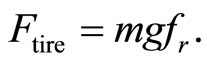
The rolling resistance force is defined by:
 (2)
(2)
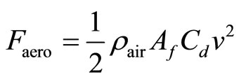
The aerodynamic resistance torque is defined as follows:
 (3)
(3)
The rolling resistance force is usually modeled as:
 (4)
(4)
where r is the tire radius, m is the vehicle total mass,  is the rolling resistance force constant, g the gravity acceleration,
  is Air density,
  is the aerodynamic drag coefficient,
  is the frontal surface area of the vehicle, v is the vehicle speed,
  is the road slope angle. Values for these parameters are shown in Table 1.
3. Direct Torque Control Strategy
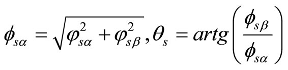
The basic DTC strategy is developed in 1986 by Takahashi. It is based on the determination of instantaneous space vectors in each sampling period regarding desired flux and torque references. The block diagram of the original DTC strategy is shown in Figure 2. The reference speed is compared to the measured one. The obtained error is applied to the speed regulator PI whose output provides the reference torque. The estimated stator flux and torque are compared to the corresponding references. The errors are applied to the stator flux and torque hysteresis regulators, respectively. The estimation value of flux and its phase angle is calculated in expression
 (5)
(5)
 (6)
(6)
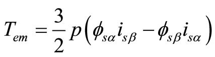
And the torque is controlled by three-level Hysteresis. Its estimation value is calculated in expression (7).
 (7)
(7)
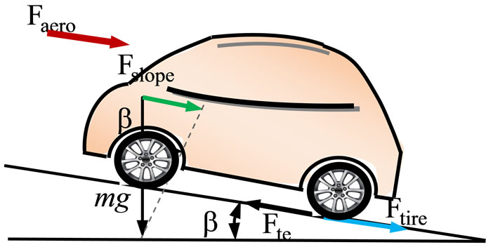
Figure 1. The forces acting on a vehicle moving along a slope.
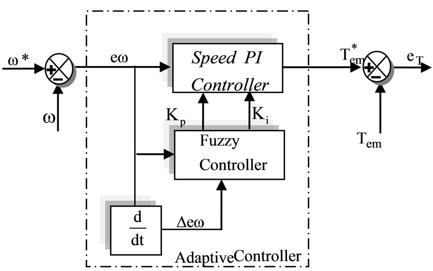
Figure 2. PI gains online tuning by fuzzy logic controller.
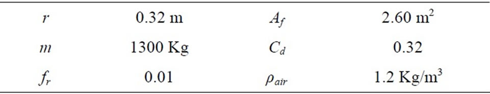
Table 1. Parameters of the electric vehicle model.
4. Intelligent Fuzzy PI Controller
Fuzzy controllers have been widely applied to industrialprocess. Especially, fuzzy controllers are effective techniques when either the mathematical model of the system is nonlinear or no the mathematical model exists. In this paper, the fuzzy control system adjusts the parameter of the PI control by the fuzzy rule. Dependent on the state of the system. The adaptive PI realized is no more a linear regulator according to this principle. In most of these studies, the Fuzzy controller used to drive the PI is defined by the authors from a series of experiments [5-8].
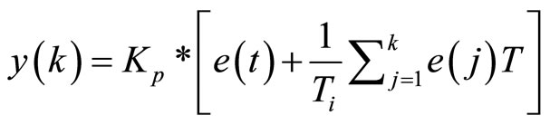
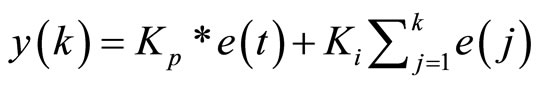
The expression of the PI is given in the Equation (2).
 (8)
(8)
where:
 : Output of the control;
![]() : Input of the control. The error of the reference current
: Input of the control. The error of the reference current  and the injected speed
 ;
; ![]() Parameter of the scale;
Parameter of the scale;  Parameter of the integrator.
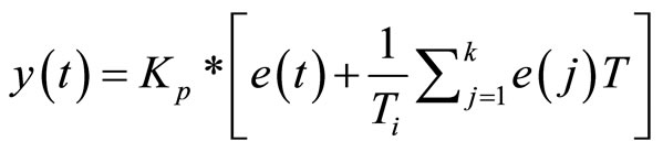
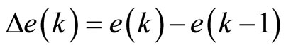
The discrete equation:
 (9)
(9)
where:
 : Output on the time of k th sampling;
 : Error on the time of k sampling;
  Cycle of the sampling
On-line Tuning:
The on-line tuning equation for kp and ki are shown below:
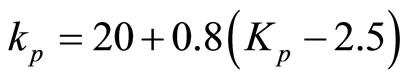 (10)
(10)
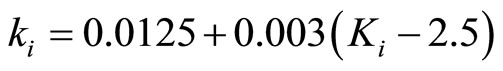 (11)
(11)
The frame of the fuzzy adaptive PI controller is illustrated in Figure 2.
The linguistic variables are defines as {NL, NM, NS, Z, PS, PM, PB} meaning negative large, negative medium, negative small, zero, positive small, positive medium, positive big.
The Membership function is illustrated in the Figures 3-6.
The view plot surface of fuzzy controller for kp and ki are shown in Figures 7 and 8 respectively.
Table 2 shows the fuzzy tuning rules.
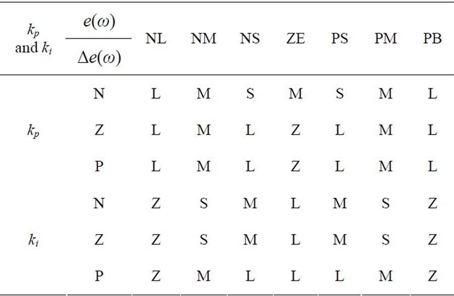
Table 2. Fuzzy tuning rules.
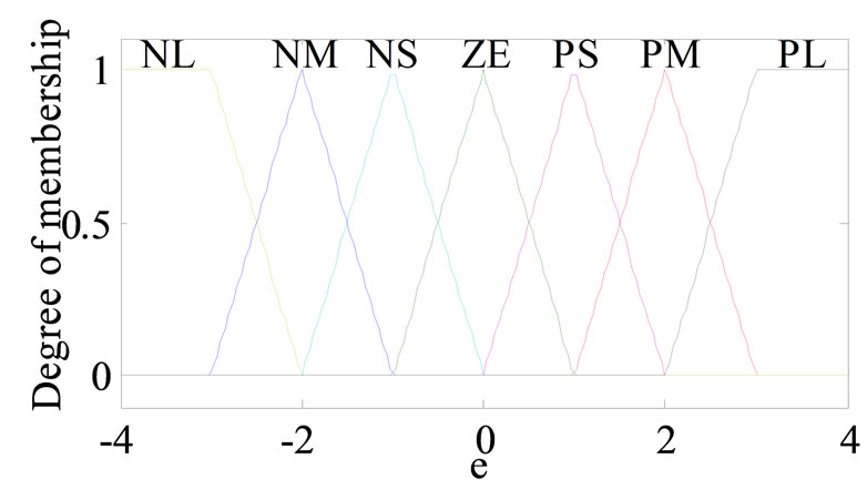
Figure 3. The membership function of input e(k).
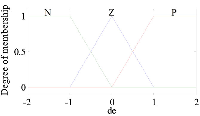
Figure 4. The membership function of input Δe(k).
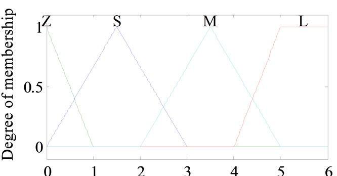
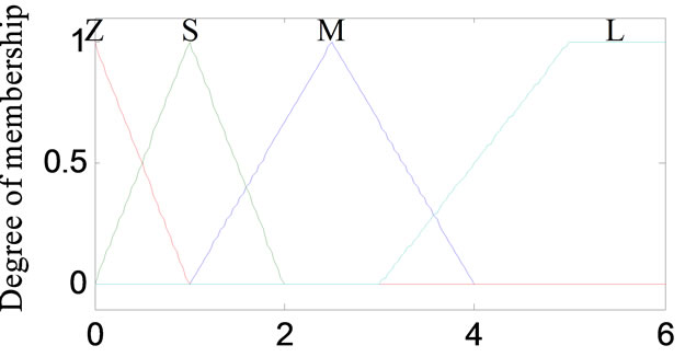
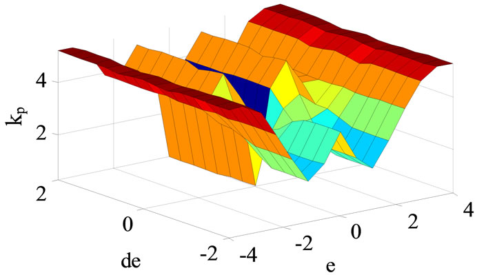
Figure 7. View plot surface of fuzzy controller for kp.
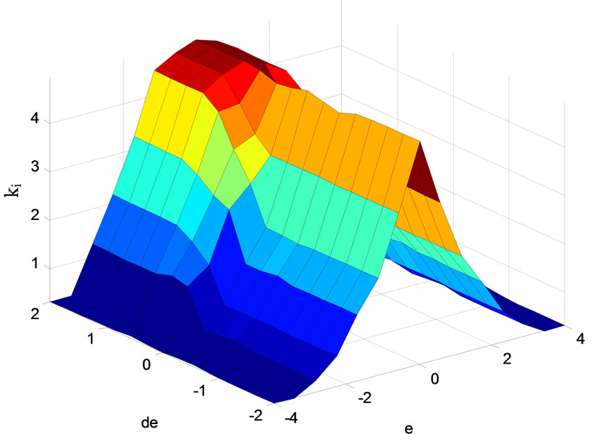
Figure 8. View plot surface of fuzzy controller for ki.
5. Simulation Results
In order to analyze the driving wheel system behavior, Simulations were carried using the model of Figure 9. The following results were simulated in MATLAB and its divided in two phases. The first one deal with the test of the EV performances controlled with DTC strategy under several topology variation in the other hand we show the impact of this controller on vehicle power electronics performances. Only the right motor simulations are shown. The assumption that the initialized lithiumion battery SOC is equal to 70% during trajectories.
5.1. Intelligent Fuzzy PI Controller for Direct Torque Control Scheme
The topology studied in this present work consists of three phases: the first one is the beginning phase’s with speed of 80 Km/h in straight road topology, the second phase present the curved road with the same speed, finally the 4WD moving up the descent road of 10% under 80 Km/h, the specified road topology is shown in Figure 10, when the speed road constraints are described in the Table 3.
Refereed to Figure 11 at time of 2 s the vehicle driver turns the steering wheel on a curved road at the right side with speed of 80 Km/h, the assumption is that the four motors are not disturbed. In this case the front and rear driving wheels follow different paths, and they turn in the same direction but with different speeds. The electronic differential acts on the four motor speeds by decreasing the speed of the driving wheel on the right side situated inside the curve, and on the other hand by increasing the wheel motor speed in the external side of the curve. The behaviors of these speeds are given in Figure 11. At t = 3 s the vehicle situated in the second curve but in the left side, the electronic differential compute the novel steering wheels speeds references in order to stabilize the vehicle inside the curve. The battery initial SOC of 70 % is respected. In this case the driving wheels follow the same path with no overshoot and without error which can be justified with the good electronic differential act coupled with DTC performances.
Figures 12-15 show the variation of kp and ki of the four intelligent speed controller.
Figure 16 describes the variation of current for the front motor right in different phases. In the first step and to reach 80 Km/h, the EV demands a current of 48.75 A for each motors which explained with electromagnetic torque of 138.20 N.m. In the curved road the current and electromagnetic torque demand are computed using the electronic differential process according to the driver decision by means that the speed reference of each wheels is given by the electronic differential computations witch convert the braking angle in the curve on linear speeds. Figure 17 shows the electromagnetic torque of the front motor right. The third phase explains the effect of the descent slopped road the electromagnetic torque decrease and the current demand undergo half of the current braking phases. The presence of descent causes a great decrease in the phase current of each motor by means that the sloped force became an motor force. They develops approximately 96.17 N.m each one. The linear speeds of the four induction motors stay the same and the descent sloped road does not influence the torque control of each
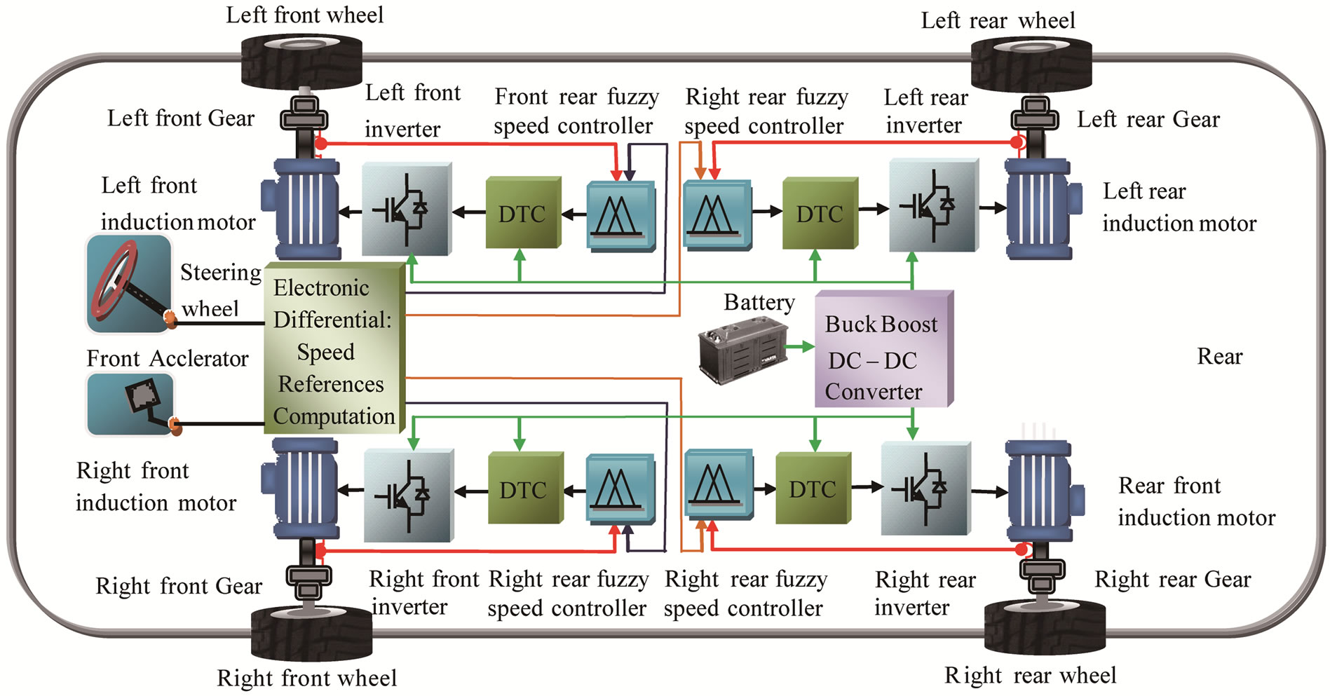
Figure 9. The driving wheels control system.
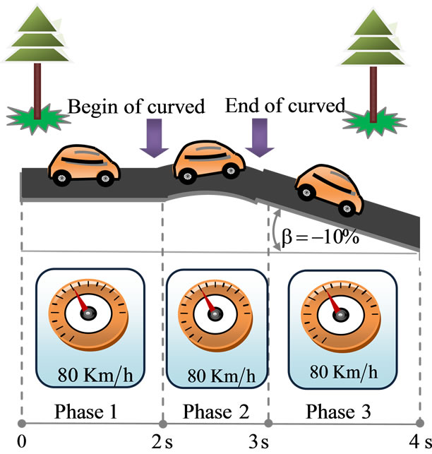
Figure 10. The chosen road topology of tests.
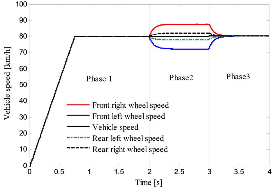
Figure 11. Variation of vehicle speeds in different phases.
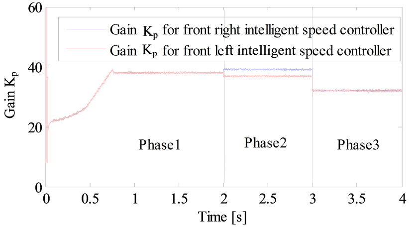
Figure 12. Variation gain kp of intelligent fuzzy PI for the front right and left speed controller.
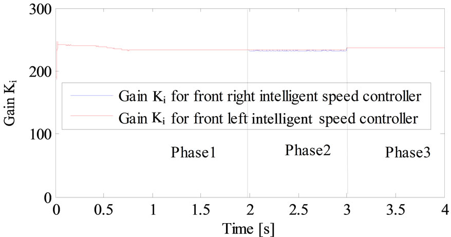
Figure 13. Variation gain ki of intelligent fuzzy PI for the front right and left speed controller.
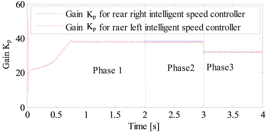
Figure 14. Variation gain kp of intelligent fuzzy PI for the rear right and left speed controller.
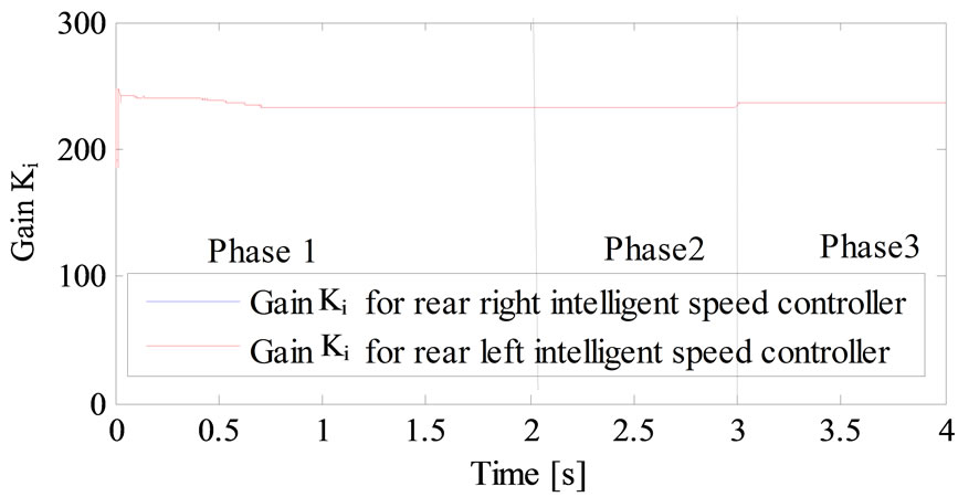
Figure 15. Variation gain ki of intelligent fuzzy PI for the rear left and left speed controller.
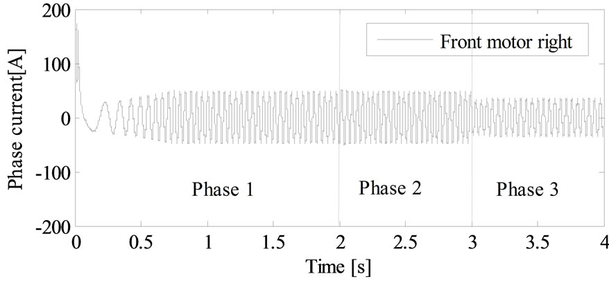
Figure 16. Variation of phase current of the front motor right in different phases.
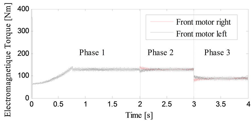
Figure 17. Variation of electromagnetic torque of the front motor right in different phases.
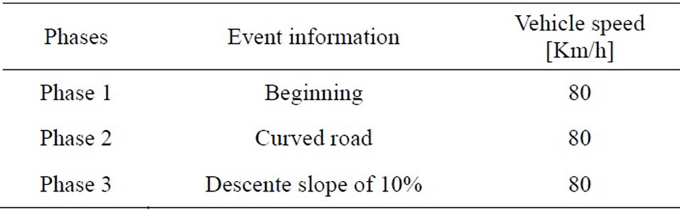
Table 3. The driving road topology description.
wheels. The results are listed in Table 4.
According to the formulas (1), (2), (3) and (4) and Table 4, the vehicle resistive torque was 127.60 N.m in the first case (beginning phase) when the power propulsion system resistive one is 127.60 N.m in the curved road. The driving wheels develop more and more efforts to satisfy the traction chain demand which justify a resistive torque equal to 127.60 N.m in the third descent slopped phase. The result prove that the traction chain under descent demand develop less effort comparing with the breaking phase case’s by means that the vehicle needs the half of its energy in the descent sloped phase’s compared with the sloped one’s as it specified in Table 5 and Figure 17.
5.2. Power Electronics
The Lithium-ion battery must be able to supply sufficient power to the EV in accelerating and decelerating phase, which means that the peak power of the batteries supply must be greater than or at least equal to the peak power of the both electric motors. The battery must store sufficient energy to maintain their SOC at a reasonable level during driving, the Figure 18, describe the changes in the battery storage power in different speed references.
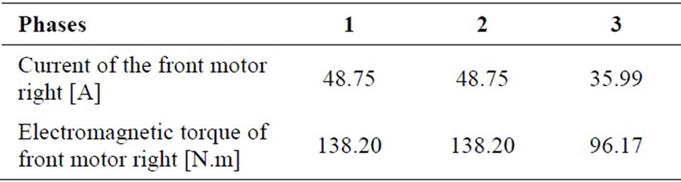
Table 4. Values of phase current driving force of the right motor in different phases.
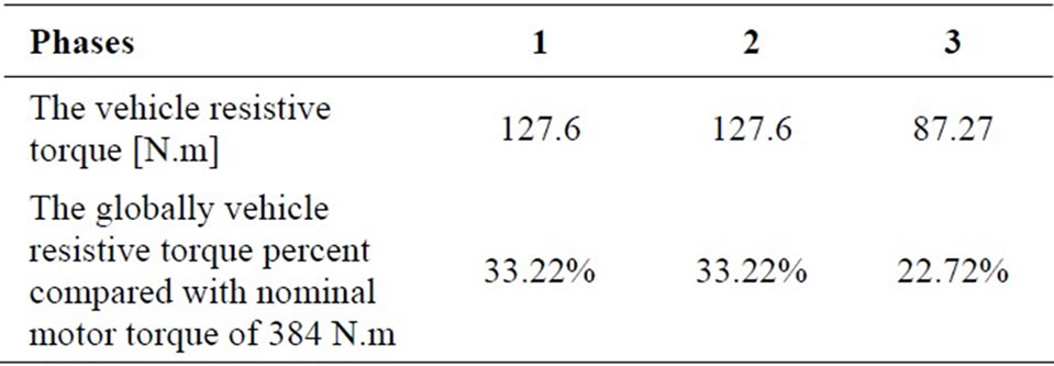
Table 5. Variation of vehicle torque in different phases.
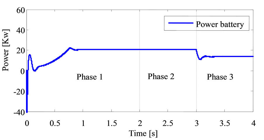
Figure 18. Variation of Lithium-ion battery power in different phases.
It is interesting to describe the power distribution in the electrical traction under several speed references as it described in Table 6. The battery provides about 20.73 Kw in the first phase in order to reach the electronic differential reference speed of 80 Km/h. In the second phase (phase 2: curved phase’s) the demanded power battery stay the same which present amount of 66.87% of the globally nominal power battery (31 Kw). In third phase the battery produced power equal to 13.73 Kw under descent slopped road state. The battery produced power depend only on the electronic differential consign by means the courved and descente sloped road driver state which can be explained by the battery SOC of Figure 19.
Figure 19 explains how SOC in the Lithium-ion battery changes during the driving cycle; it seems that the SOC decreases rapidly at acceleration, by means that the SOC range’s between 68.44% to 70% during all cycle’s phases from beginning at the end cycles.
At t = 4 s, the battery SOC becomes lower than 68.44% (it was initialized to 70% at the beginning of the simulation).
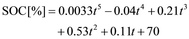
Table 7 reflects the variation of SOC in different simulations phases. The relationship between SOC and left time in three phases are defined by the flowing linear fitting formula:
 (12)
(12)
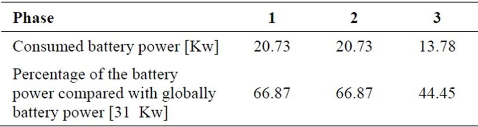
Table 6. Variation of battery power in different trajectory phases.
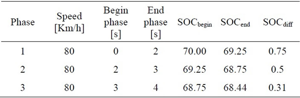
Table 7. Evaluation of SOC [%] in the different phases.
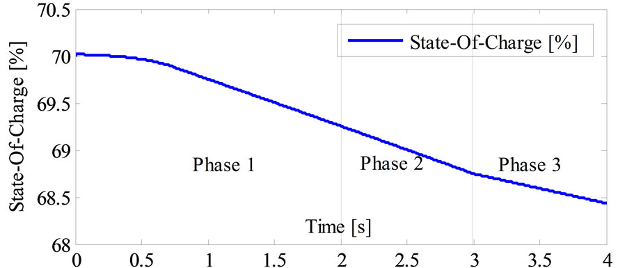
Figure 19. Battery efficiency versus state-of-charge.
Moreover the simulation results specified by Figure 20, we can define the relationship between the sate of charge and the traveled distance in each cases as it shown in Table 8 and the relationship between power consumed and state of charge during each phase as it shown in Table 9, the first one (beginning phase) is defined by the linear fitting formula:
 (13)
(13)
This power is controlled by the Buck Boost DC-DC converter current and distribute accurately for three phases. Figure 21 shows the buck boost DC-DC converter robustness under several speed cycles. The buck boost converter is not only a robust converter which ensures the power voltage transmission but also a good battery recharger in deceleration state that help to perfect the vehicle autonomous with no voltage ripple.
6. Conclusion
The research outlined in this paper has demonstrated the
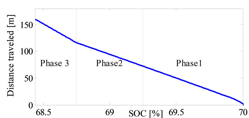
Figure 20. Evaluation traveled distance en function the SOC.
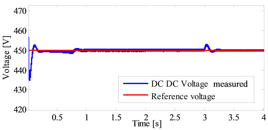
Figure 21. Buck boost DC-DC converter behavior under several speed variations.
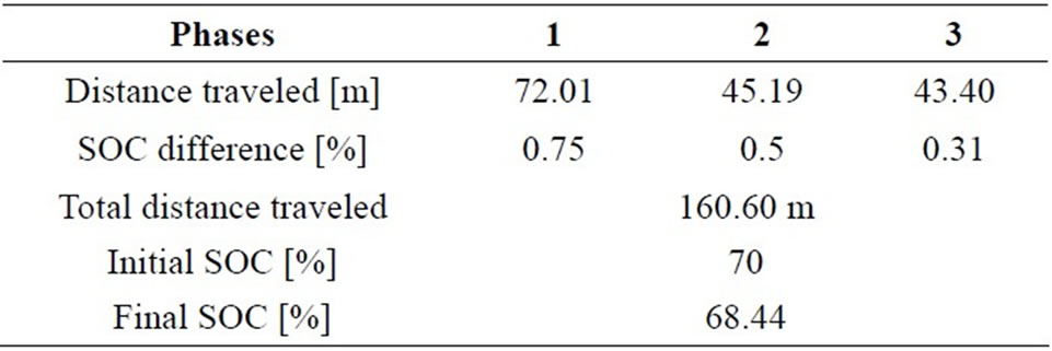
Table 8. Evaluation of distance traveled and SOC.
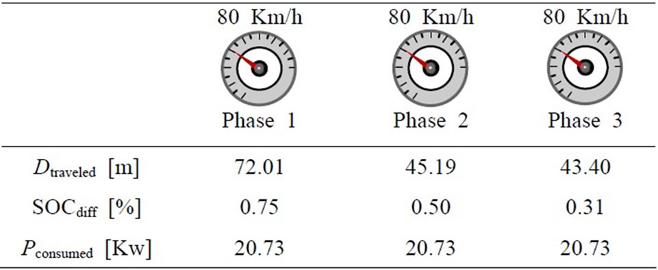
Table 9. The relationship between the traction chain power electronics characteristics and the distance traveled in differ-ent phases.
feasibility of improved vehicle stability for 4WD electric vehicle using DTC controls. DTC with intelligent fuzzy speed controller is able to adapt itself the suitable control parameters which are the proportional and integral gains  and ki to the variations of vehicle torque. This method was improved proposed traction system steering and stability during different trajectory this. The advantage DTC controller is robustness and performance, there capacity to maintain ideal trajectories for four wheels control independently and ensure good disturbances rejections with no overshoot and stability of vehicle perfected ensured with the speed variation and less error speed. The 4WD electric vehicle was proved best comportment and stability during different road path by maintaining the motorization error speed equal zeros and gives a good distribution for electromagnetic torque. The electric vehicle was proved efficiency comportment under different road topologies.
REFERENCES
- J. Wang, Q. Wang, L. Jin and C. Song, “Independent Wheel Torque Control of 4WD Electric Vehicle for Differential Drive Assisted Steering,” Mechatronics, Vol. 21, 2011, pp. 63-76. doi:10.1016/j.mechatronics.2010.08.005
- J. Wang, Q. Wang and L. Jin, “Modeling and Simulation Studies on Differential Drive Assisted Steering for EV with Four-Wheel-Independent-Drive,” Proceedings of the 4th IEEE Vehicle Power and Propulsion Conference (VPPC2008), Harbin, 3-5 September 2008, pp. 1-7.
- H. Yoichi, T. Yasushi and T. Yoshimasa, “Traction Control of Electric Vehicle: Basic Experimental Results Using the Test EV ‘UOT Electric March’,” IEEE Transaction on Industry Application, Vol. 34, No. 5, 1998, pp. 1131-1138.
- F. Wu and T. J. Yeh, “A Control Strategy for an Electrical Vehicle Using Two In-Wheel Motors and Steering Mechanism,” Proceedings of AVEC’08, Kobe, 6-9 October 2008, pp. 796-801.
- M. Q. Gao and S. H. He, “Self-Adapting Fuzzy-PID Control of Variable Universe in the Non-Linear System,” 2008 International Conference on Intelligent Computation Technology and Automation, Changsha, 20-22 October 2008, pp. 473-478.
- J.-Y. Chen, P.-S. Tsai and C.-C. Wong, “Adaptive Design of a Fuzzy Cerebellar Model Arithmetic Controller Neural Network,” IEEE Proceedings of Control Theory and Applications, Vol. 152, No. 2, 2005, pp. 133-137.
- C.-M. Lin and Y.-F. Peng, “Adaptive CMAC-Based Supervisory Control for Uncertain Nonlinear Systems,” IEEE Transactions on Systems, Man, and Cybernetics—Part B: Cybernetics, Vol. 34, No. 2, 2004, pp. 1248-1260.
- H. G. Han, C.-Y. Su and Y. Stepanenko, “Adaptive Control of a Class of Nonlinear Systems with Nonlinearly Parameterized Fuzzy Approximators,” IEEE Transactions on Fuzzy Systems, Vol. 9, No. 2, 2001, pp. 315-323. doi:10.1109/91.919252