Wireless Engineering and Technology
Vol.3 No.2(2012), Article ID:18932,4 pages DOI:10.4236/wet.2012.32013
An Electrically Scanned Lens Antenna for 2-D Scanning*
![]()
State Key Lab of Millimeter Waves, Southeast University, Nanjing, China.
Email: wangzx@seu.edu.cn
Received November 25th, 2011; revised December 17th, 2011; accepted January 30th, 2012
Keywords: Electrically Scanning; Binary Diffractive Lens; Voltage-Controlled Ferroelectric Lens
ABSTRACT
An electrically scanned lens antenna for two dimensional scanning is presented. The antenna system is composed of a (N × 1) feed array, a binary diffractive dielectric lens (BDL) and a voltage-controlled ferroelectric lens (VCFL). The feeds at different offset foci of the BDL generate receiving beams pointing to different angles to perform beam scanning in one dimension; the VCFL made of ferroelectric slabs which show linear permittivity gradient when loaded with corresponding DC voltages generate linear phase shift to steer the beam in the other dimension.
1. Introduction
The traditional phased array antenna (PAA) is composed of many radiating elements each with a phase shifter. Beams of different scanning angles are formed by shifting the phase of the signal of each radiating element. Compared with mechanism scanning antennas, PAA systems have many good characteristics such as high scanning speed, no mechanical inertia and the ability to generate agile beams under computer control, however, a PAA system usually consists of thousands of radiating elements (N × M, N rows and M columns) and each with a phase shifter, which make the system very complex and expensive. Phase shifters using ferroelectric materials have been proposed [1,2] and based on this concept a new concept of phased array depending on voltage-controlled ferroelectric lens (VCFL) has been given by J. B. L. Rao [3], etc. The new phased array system contains only (N + M) electrically controlled units for generating scanning beams, and the unit number is far less than (N × M), so the complexity and cost of system can be reduced markedly. In this paper, we present a novel lens antenna consist of a (N × 1) feed array, a binary diffractive dielectric lens (BDL) [4] and a VCFL. To generate electrically controlled scanning beams there need only an N-channel electric switch and M voltage-controllers.
2. Antenna Configuration and Simulation
The configuration of the proposed antenna system is shown in Figure 1, where the system consists of a (N × 1) feed array, a BDL and a VCFL. Cross section of a BDL along x-axis is shown in Figure 2, the BDL has the same focusing property as that of a common hyperbolic lens, however, the BDL has the advantages of low profile and weight, and what is most import is that the BDL can be integrated with the VCFL into a seamless compound lens profited from its planar structure. The (N × 1) feed array is set at the focal plane of the BDL, the feed at different offset positions will generate different scanning beams pointing to corresponding direction in the YOZ plane, for example, receiving beams generated by feed A and feed B point to the target at A’ and B’ respectively. All the beams generated by the (N × 1) feed array perform the scanning in the YOZ plane. The VCFL is made up of ferroelectric slabs sandwiched between conducting plates [3] as shown in Figure 3.
The dielectric constants  of the ferroelectric slabs can be changed by applying and varying the DC electric field which is controlled by the computer.
Figure 1. The proposed antenna system.
Figure 2. Cross section of the BDL.
Figure 3. Structure of a VCFL.
The feeds array are so set that the E-field direction of the eradiated waves is along x-axis. The electromagnetic waves radiated by the horn placed at the focal point of the BDL turn to quasi-plane waves after passing through the BDL, the phase delays are different after the quasiplane waves passing through different ferroelectric slabs due to different dielectric constants, as explained in [3], when the phase distribution is linear gradient along the output plane of the VCFL, the antenna generate a scanning beam in the E-plane (e.g. XOZ plane as shown in Figure 1) normal to the phase plane of the waves. By adjusting the voltages , the direction of the scanning beam can be shifted accordingly.
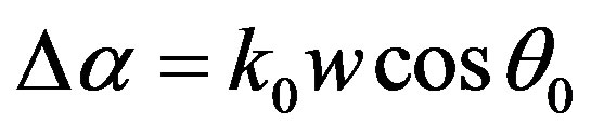
To determine the values of , let’s refer to Figure 4, the phase differences between the plane waves arriving at the neighboring two slabs is
 (1)
(1)
where
θ0 is elevation angle of the target in XOZ plane, w is the width of the ferroelectric slab.
The dielectric constants of the two neighboring slabs should satisfy the following equation
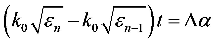 (2)
(2)
where t is the thickness of the ferroelectric slab.
Considering the phase differences period of 2π, when
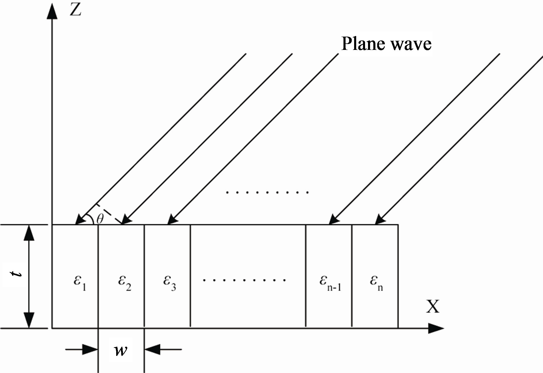
Figure 4. Determination of the dielectric constants of the ferroelectric slabs.
the phase differences between εn and ε1 is larger than 2π, the Equation (2) should be adjusted as:
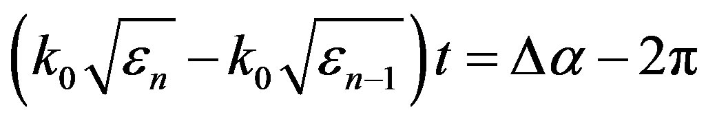 (3)
(3)
A compound lens antenna is designed at frequency of 10GHz and the radiation pattern is computed using finite difference time domain method(FDTD) [5,6] to show its characteristic. Due to restriction of the computer resource, the aperture of the antenna is set to be 700 mm × 700 mm. The focal length f of the BDL is 280 mm and the relative dielectric constant of the BDL 3.78. The thickness and the width of the ferroelectric slab are selected as: t = w = 40 mm, and to cover the aperture of the BDL seventeen ferroelectric slabs are need.
At first, the dielectric constants of all the ferroelectric slabs are set to be 3.78 and a standard rectangular waveguide feed is placed at three positions: P1 (x = 0, y = 0, z = –f), P2 (x = 23 mm, y = 0, z = –f) and P3 (x = 46 mm, y = 0, z = –f) respectively to calculate the radiation pattern of the antenna, which show the scanning characteristic of the compound lens in YOZ plane. The numerical results of the radiation pattern are obtained by FDTD and shown in Figure 5, and it is can be seen from the radiation pattern that there are three scanning beams in YOZ plane corresponding to the three feeds at different positions.
Then place the feed waveguide at the focal point and set the dielectric constants of the ferroelectric slabs corresponding to  2˚, 4˚ and 8˚ respectively to calculate the scanning properties of the antenna in the XOZ plane. The base dielectric constant of the ferroelectric is selected to be 3.78 and all the dielectric constants of the ferroelectric slabs for
  and
and  determined by Equations (2) and (3) are listed in Table 1. The radiation pattern results are also calculated by FDTD and shown in Figure 6, it can also form the figure that there exist three scanning beams in XOZ plane pointing to
  2˚, 4˚ and 8˚ respectively.
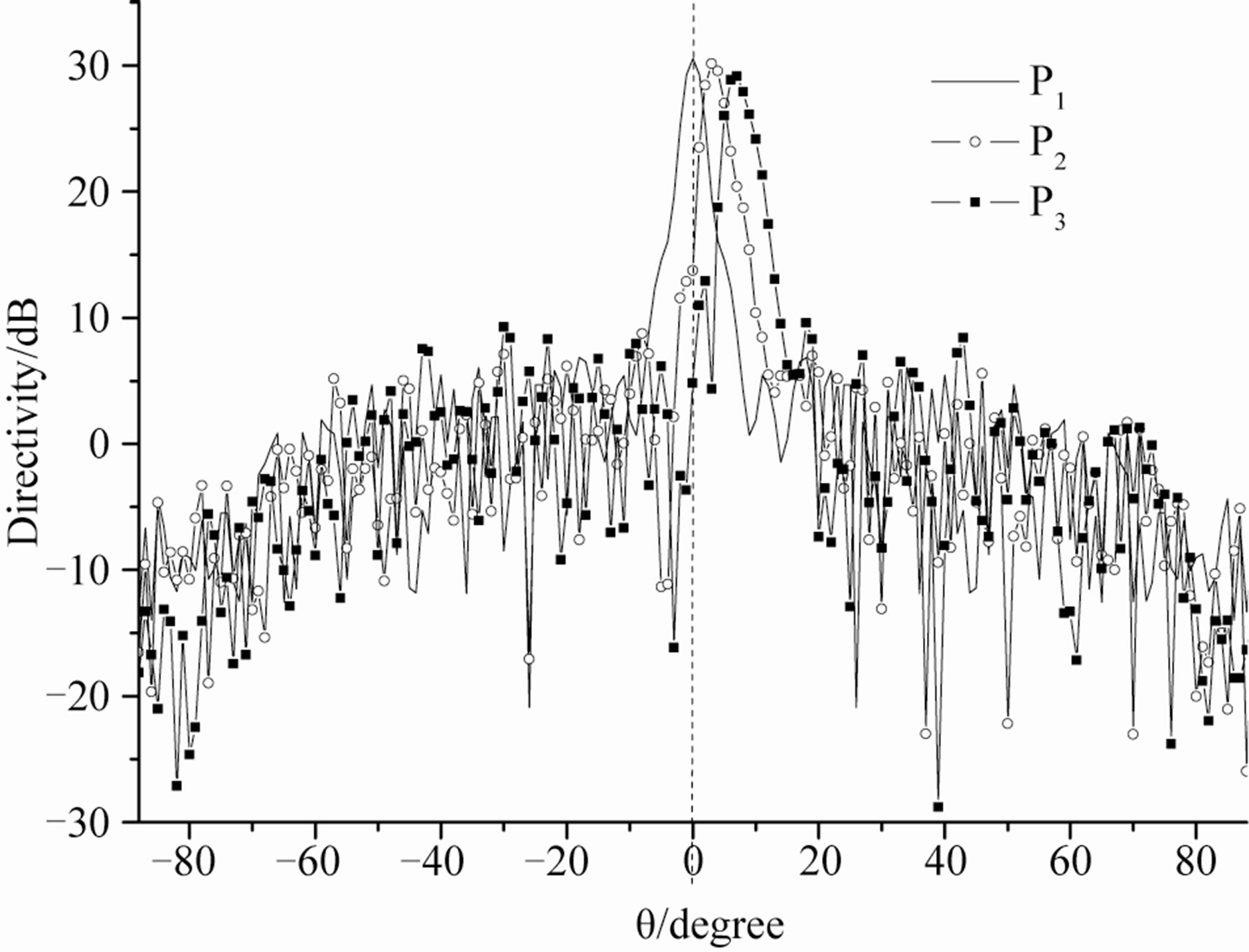
Figure 5. Scanning beams in YOZ plane.
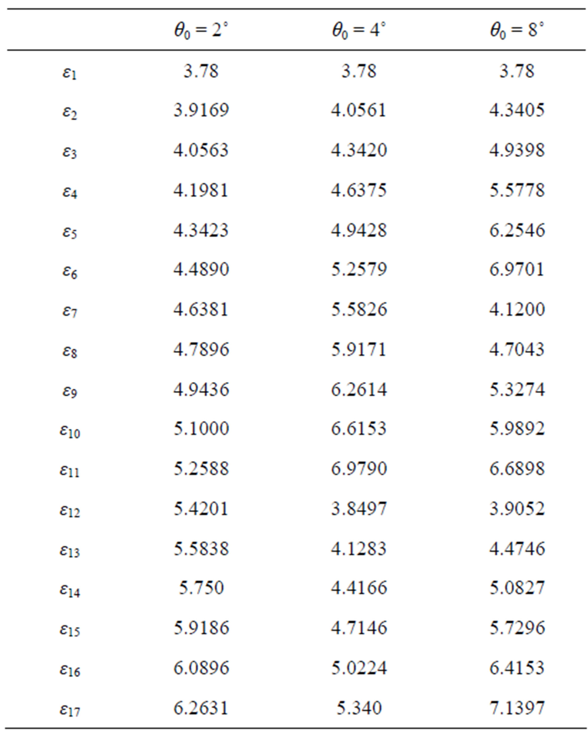
Table 1. Dielectric constants of the ferroelectric slabs.
3. Conclusion
In this paper, a novel compound lens antenna based on the binary diffractive lens BDL and voltage-controlled ferroelectric lens is presented. The scanning beams of the compound lens antenna can be electrically controlled using only an N-channel electric switch and M voltage-
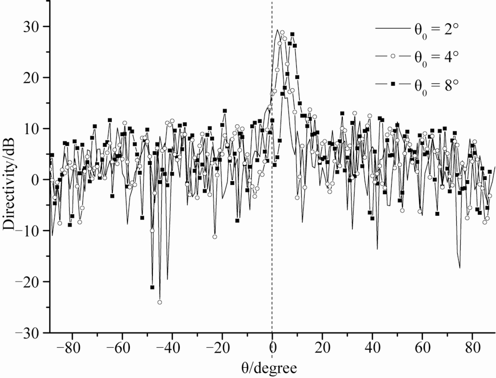
Figure 6. Scanning beams in XOZ plane.
controllers, which are far less than that of a traditional phased array antenna system. A compound lens are designed, and the scanning properties of the lens in the XOZ and YOZ planes are simulated and presented; due to restriction of the computer resources, only a small compound lens are able to be simulated, however, the numerical results show that the presented compound lens antenna is able to perform 2-D scanning.
REFERENCES
- V. K. Varadan, D. K. Ghodgaonkar, V. V. Varadan, J. F. Kelly and P. Gilkerdas, “Ceramic Phase Shifters for Electronically Steerable Antenna Systems,” Microwave Journal, Vol. 35, 1992, pp. 116-127.
- R. W. Babbitt, T. E. Koscica and W. C. Drach, “Planar Microwave Electro-Optic Phase Shifters,” Microwave Journal, Vol. 35, 1992, pp. 63-79.
- J. B. L. Rao, D. P. Patel and V. Krichevsky, “VoltageControlled Ferroelectric Lens Phased Arrays,” IEEE Transactions on Antennas and Propagation, Vol. 47, No. 3, 1999, pp. 458-468. doi:10.1109/8.768780
- Z. X. Wang and W. B. Dou, “Design and Analysis of Several Kinds of Dielectric Lens Antennas,” Journal of Electromagnetic Waves and Applications, Vol. 20, No. 12, 2006, pp. 1643-1653. doi:10.1163/156939306779292327
- A. Taflove, “Advances in Computational Electrodynamics: The Finite-Difference Time-Domain Method,” Artech House, Inc., Boston, 1998.
- Z. X. Wang and W. B. Dou, “Design and Analysis of Thin Diffractive/Refractive Lens Antennas,” Journal of Electromagnetic Waves and Applications, Vol. 20, No. 15, 2006, pp. 2239-2251. doi:10.1163/156939306779322558
NOTES
*Supported by NSFC (61071046).