Wireless Engineering and Technology
Vol.2 No.2(2011), Article ID:4545,7 pages DOI:10.4236/wet.2011.22011
Inhomogeneous Perforated Reflect-Array Antennas
![]()
Department of Electrical Engineering, Iran University of Science and Technology, Tehran, Iran.
Email: {M_Moeinifard, Khalaja}@iust.ac.ir
Received October 15th, 2010; revised February 26th, 2011; accepted February 28th, 2011.
Keywords: perforated substrate, Reflect-Array Antenna
ABSTRACT
A new reflect-array antenna structure is proposed. This structure utilizes a perforated substrate as a reflecting surface with the lattice of different holes. The effective electric permittivity of the dielectric substrate is altered by drilling holes with different diameter and spacing, which provide an in-homogeneous dielectric layer. This in-homogeneous dielectric layer can be controlled by these holes to collimate the reflected waves in the special direction. Absence of resonator elements in this structure will reduce the dielectric and conductor losses, which are the main losses in reflect-array antennas at resonance frequency. In addition, a simple method based on an equivalent circuit model is introduced for designing and analyzing this kind of antennas. Using this method, the suitable values of the diameter and spacing of the holes at each point on the reflecting surface are obtained. Some proposed antennas are designed at millimeter wave frequency and simulated by full-wave analyzer; CST Microwave Studio software to verify theoretical results.
1. Introduction
A reflect-array antenna is an array of resonator elements that are placed on a surface and illuminated by a primary feed antenna, which is placed at a particular distance from the array. The reflect-array surface transforms the field radiated by the feed into a phase-coherent beam in a prescribed direction. The focusing effect can be obtained by slightly modifying the shape or size of resonator elements, so that the phase of the reflection coefficient locally changes. Typically, only one relevant geometrical dimension is modified. Therefore, a basic step in the design of reflect-array antennas is the calculation of the phase diagram, which is the plot of the phase of the reflection coefficient versus the relevant geometrical dimension of the element. Due to the quasi-periodicity of the structure, the phase diagram can be calculated under the hypothesis of an infinite periodic array. For a good design of reflect-array antennas, the phase diagram of the selected element should cover a wide phase range, since the focusing effect could require any phase of the reflection coefficient. Microstrip patch antenna is one of the candidates, which used widely as resonator element in the reflect-array antennas. This element has given several configurations of reflect-array, in which, the required phase diagrams are obtained by varying the shape and size of etched resonant conducting elements [1-5]. However, at millimeter waves, the mutual coupling between microstrip elements printed on standard substrates becomes significant; in addition, the conductor and surface wave loss are severe. To overcome these limitations, other candidate, dielectric resonator antennas (DRA) have been introduced due to their low loss, relatively wide bandwidth, high radiation efficiency and low mutual coupling [6-8]. However, these antennas have other shortcomings such as complicated mechanical processes to form the desired shape of the DRA or critical bonding processes to locate the DRA element at exact location at millimeter wave. Here, we have taken a rather new approach to reduce all mentioned short comes. The idea is to construct an in-homogeneous dielectric layer as a reflecting surface. The dielectric layer with variable electric permittivity provides the required phase shift at each point on the reflect-array surface to produce a reflected beam in a specific direction. Using perforated substrate with variable holes distribution provides this in-homogeneous dielectric layer. The effective permittivity of the substrate is controlled by drilling holes with different diameter and spacing. If the period of the holes is small compared to a wavelength, the quasi-static techniques will result in a good estimate of the electric permittivity. So, at first the phase response of the infinite substrate versus the variation of the electric permittivity is plotted and modeled with an equivalent circuit. Then, by implementing this phase curve and the effective electric permittivity relation, the proper diameter and spacing of the holes at each element are calculated. Finally, the usefulness of the proposed structure and its performance are verified by two comprehensive examples. These examples are simulated by the CST Microwave Studio TM package, which is based on the finite integration technique [9].
2. Analysis of Perforated Substrate
The critical feature of perforated reflect-array implementation is how the individual elements are made to scatter the incident wave with the desired phases. Perforated substrate with variable holes distribution is used to control the reflection phase. In practice, to implement such in-homogeneous substrate, it must be subdivided into small homogeneous elements with uniform holes distribution. The geometry of a subdivided perforated substrate and the corresponding homogeneous elements are shown in Figure 1. The diameter (d) and spacing (g) of the holes determines the effective electric permittivity of each element. If the hole diameter and spacing remains less than a half-wavelength, it has been observed that the effective electric permittivity of the substrate will approximately be the volumetric average of the free-space holes and remaining dielectric material [10]. The substrate perforation considered is a two-dimensional array of holes in the substrate. Each hole simply consists of removal of the dielectric material down to the ground plane. Within each column, the holes center to center distance is  and column to column center separation is
 . Finally, the effective electric permittivity can be obtained as follows
 (1)
(1)
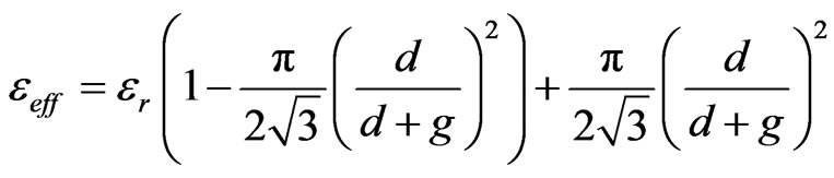
where  is the electric permittivity of substrate. This effective electric permittivity can be varied between 1 and
  by changing the holes distribution. By using the relation (1) each perforated element is replaced by an equivalent dielectric element with electric permittivity of
 . Instead of analyzing the perforated element, the equivalent dielectric element is analyzed by simple transmission line model, and in the next section, after designing and finding the proper values of these effective electric permittivities the suitable holes distributions will be obtained. By assuming the normal incident of electric field, there exist the following boundary conditions at the surface of each equivalent dielectric element [11]
 (2)
(2)
 (3)
(3)
 and
and  are inner electric and magnetic fields of dielectric element at
 , and
, and  is the incident field. In these equations,
  represents the characteristic impedance of the free space. Using these relations, equivalent circuits are obtained from the transmission line analogy as shown in Figure 2. In this figure, the mn-th element, is represented as a short circuit transmission line, in which the characteristic impedance and propagation constant are expressed as
 (4)
(4)
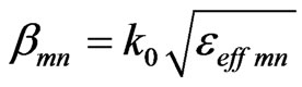 (5)
(5)
where  is the propagation constant in the free space. By considering the Figure 2 the reflection coefficient is obtained as
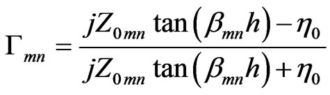 (6)
(6)
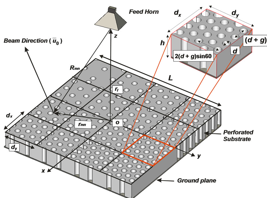
Figure 1. Total view of the elements arrangement and coordinate system for the inhomogeneous perforated reflectarray antenna.
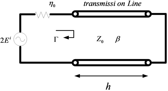
Figure 2. Equivalent transmission line model of each element.
This reflection coefficient represents the exact reflection of the fields on the surface of the mn-th equivalent dielectric element, in which both reflections from the top layer of dielectric and the conductor plane at the bottom are involved. The reflected field on each element is computed by multiplying the reflection coefficient ( ) to incident field. From relations (4)-(6) the phase of reflection coefficient is obtained as
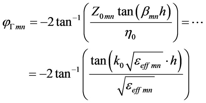 (7)
(7)
It is seen from (7) that the phase of reflection coefficient is dependent to the effective electric permittivity  of the element. It is notable, that the phase of reflection coefficient of each element has to cover 360˚ with variation of its effective electric permittivity
  in the practical range. This fact can be seen in the Figure 3, which shows a typical phase shift of an element with respect to its effective electric permittivity
  at operating frequency 30 GHz with thickness h = 3.125 mm. Also, Figure 3 shows that the theoretical calculations result agree well with the result obtained by CST simulation, in which a simple element with variable dielectric constant is simulated with periodic boundary conditions.
It must be noted that, the in-homogeneity of the reflect-array’s surface was not accounted in the analysis of elements. This assumption would not involve a significant error at the final results because of the smooth variation of the effective electric permittivities in comparison with wavelength.
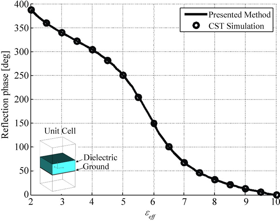
Figure 3. Phase of the reflected field for normal incidence versus the electric permittivity.
3. Design of Perforated Reflect-Array Element
In this section, the designing approach of the perforated reflect-array is introduced. A pencil beam in an arbitrary direction is formed when the phases of the reflection coefficients on the surface of the elements compensate the phase differences of elements in that direction. As shown in Figure 1, the scattered field from the perforated surface in desired main-beam pointing direction,  , will be in the form of
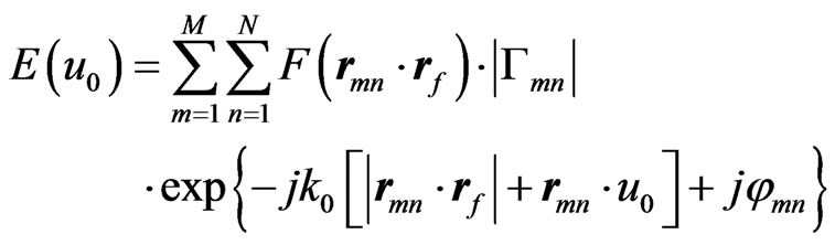 (8)
(8)
where F is the feed pattern function,  is the reflection coefficient at the mn-th element position. Terms
  and
and  are the position vectors of the mn-th element and the feed horn antenna, respectively. Phase
  is the required phase of the scattered field from the mn-th element. The condition for an array aperture distribution to be co-phase in the desired direction,
  , is given by
 (9)
(9)
where  is the distance from the feed source to the mn-th array element, i.e.,
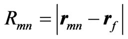 . According to the relation (7), the proper effective electric permittivity of the mn-th element (
 ) is obtained by equating the required phase shift
  with the phase of reflection coefficient
 . The key technique in the design of a perforated element is how to select the holes distribution to synthesize the element with special effective electric permittivity. By considering the relation (1), there is two degree of freedom to synthesize perforated elements: the holes diameter (d) and spacing (g) between adjacent holes (as shown in Figure 1). There is a restriction on selecting the holes diameter by drill machines. So, the perforated elements are synthesized by variable holes spacing with the constant holes diameter. After manipulating the relation (1), the required holes spacing of mn-th element is calculated as follows
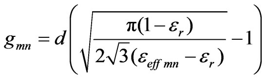 (10)
(10)
To design perforated reflect-array element, there is a factor worthy of mention. The element dimensions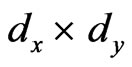 : at the relation (9) the required phase
  of mn-th element is determined at the center of the element. This causes a significant phase error, which will increase the output side lobe levels. In order to avoid this phase error, the elements size must be reduced. But there is a mechanical restriction by the holes diameter and spacing. Simulation of different element sizes shows that selecting
 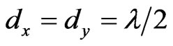 is the best choice in constructing perforated reflect-array at operating frequency 30 GHz.
4. Design Examples
In this section, the performance of perforated reflectarray antenna is verified through presenting some examples at frequency 30 GHz. In these examples both perforated substrates and equivalent inhomogeneous substrates are simulated and the results are compared with each other. As the total structures of antennas are very large, these examples were modeled and simulated only by CST Microwave Studio (MWS). In this paper, the perforated substrates in all cases are formed by holes drilled into the dielectric material Arlon AR1000 with the electric permittivity 10, dissipation factor 0.003 and thickness 3.125 mm. For the first example, we consider a 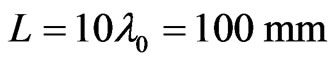 square perforated reflect-array with a broadside feed and a broadside main beam. The substrate is subdivided into 400 elements of equal size of
 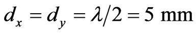 arranged in a lattice of 20 × 20 elements. A linearly polarized pyramidal horn is used for a feed antenna, with its phase center located a
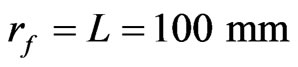 . The holes with diameters
 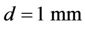 are chosen for this example. First, it is interesting to know how much the phase diagram changes with frequency. Actually, more frequency bandwidth occurs for reflect-array antenna when the phase curves have small variation toward the central frequency (±45˚) [12]. Figure 4 shows the variation of phase curves for different frequencies centered at 30 GHz. Based on this plot, bandwidth of the reflect-array element are estimated to be about 7%.
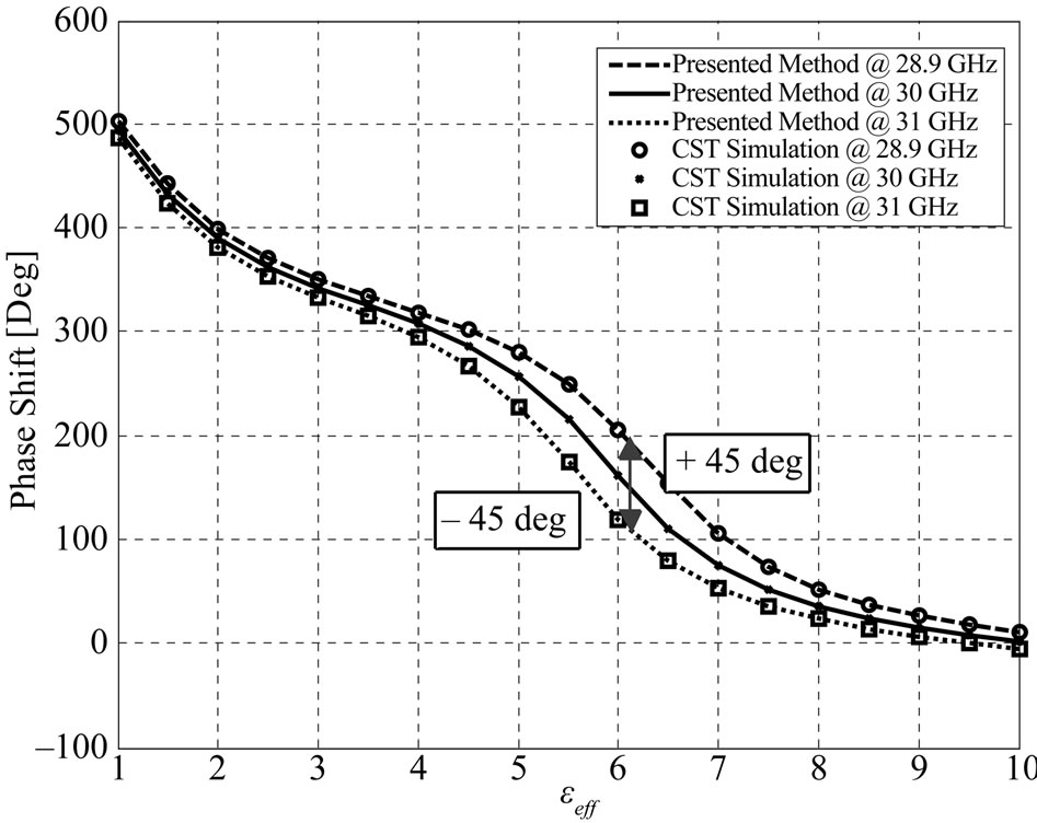
Figure 4. Curves of the reflection phases at different frequencies, to evaluate the element bandwidth.
Figure 5(a) shows the required phase shift ( ) of each element and the corresponding equivalent substrate with effective electric permittivity (
 ). Also, the perforated substrate is shown in Figure 5(b); it consists of 6208 holes which are drilled on the substrate. Each hole simply consists of removal of the dielectric material down to the ground. So, the dielectric mass covers only 51.3% of the perforated substrate, which equals to a solid substrate with same surface and 1.6 mm thickness. This reduction of dielectric mass causes the lower dielectric loss, which is more significant at millimeter wave frequencies [13].
 (a)
(a)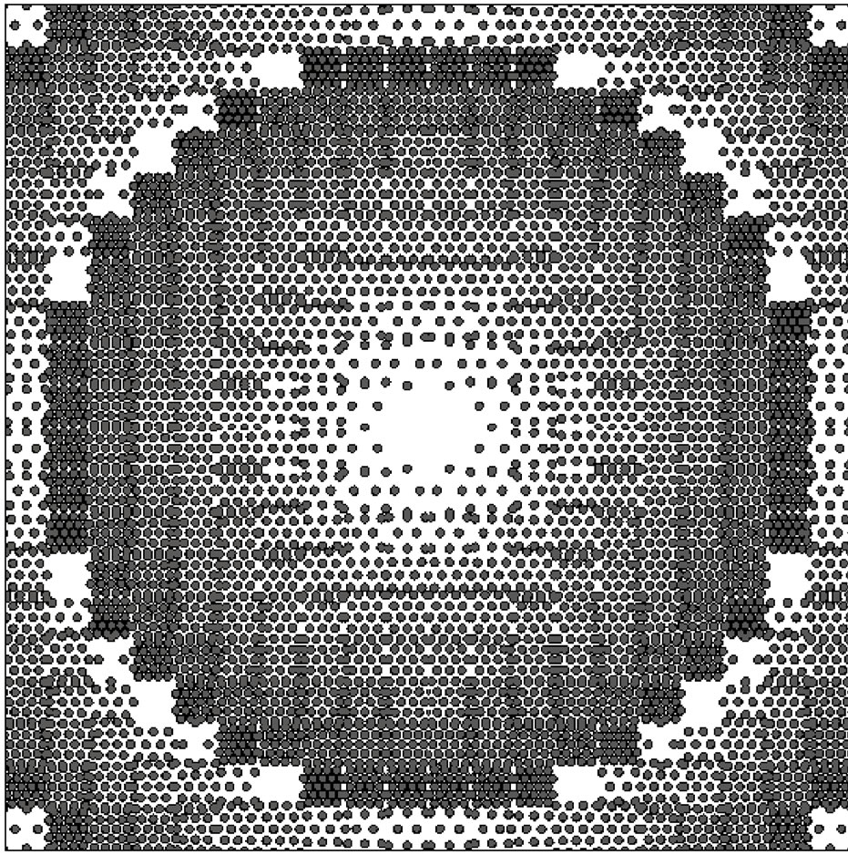 (b)
(b)
Figure 5. The design processes of broadside perforated reflect-array. (a) The required phase shifts of elements and corresponding  values; (b) The geometry of the designed perforated substrate.
Simulated structures beside the E-plane patterns of these antennas are shown in Figure 6. Note that the beams are broadside, and the maximum directivity of perforated and equivalent structures are 26.9 dB, 27.48 dB, respectively. The H-plane patterns are shown in Figure 7. The directivity of the reflect-array is defined as the ratio of the scattered intensity in the main beam direction from the reflect-array to the scattered intensity averaged over all directions. Figure 8 shows the simulated directivities against frequency. The 1-dB directivity bandwidths of the perforated and equivalent structures are 15.5%, 16.4%, respectively.
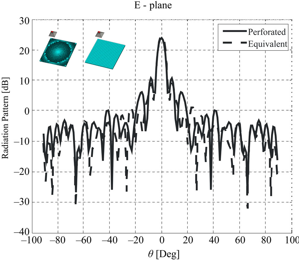
Figure 6. E-plane radiation patterns of broadside perforated and equivalent reflect-array.
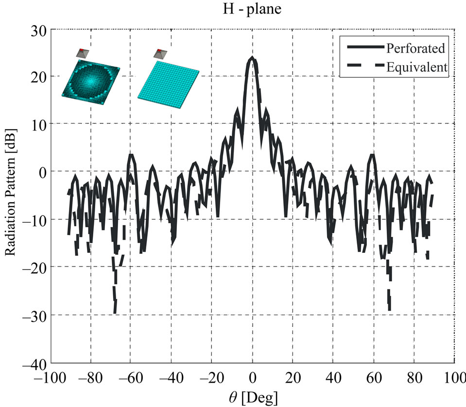
Figure 7. H-plane radiation patterns of broadside perforated and equivalent reflect-array.
To avoid the horn blockage, the reflected beam must be directed out of broadside. So, another example with the 25˚ off broadside beam direction was designed. This reflect-array consists of a square perforated substrate with dimension . The substrate is Arlon AR1000 with electric permittivity
 , loss tangent of 0.0037 and thickness 3.125 mm. It is subdivided into 400 elements of equal size of
 arranged in a lattice of 20 × 20 elements. A linearly polarized pyramidal horn is used for a feed antenna, with its phase center located at
 . The holes diameter is
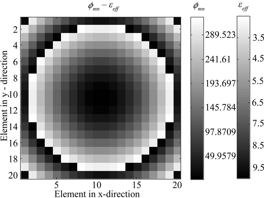
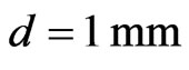 . The required phase shift, effective electric permittivity of elements and the corresponding perforated substrate are shown in Figure 9. It consists of 7376 holes, which shows that only 42.06% of the perforated substrate is covered by dielectric material. This reduction of the volumetric dielectric mass will reduce the total dielectric loses.
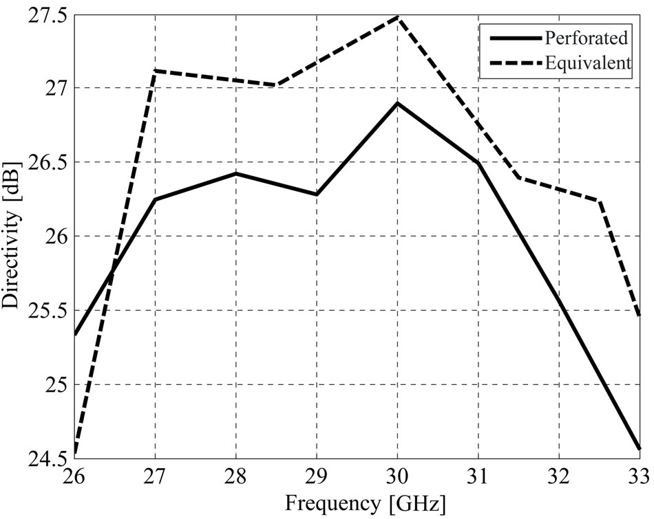
Figure 8. Directivity variations against frequency for broadside perforated and equivalent reflect-array.
 (a)
(a)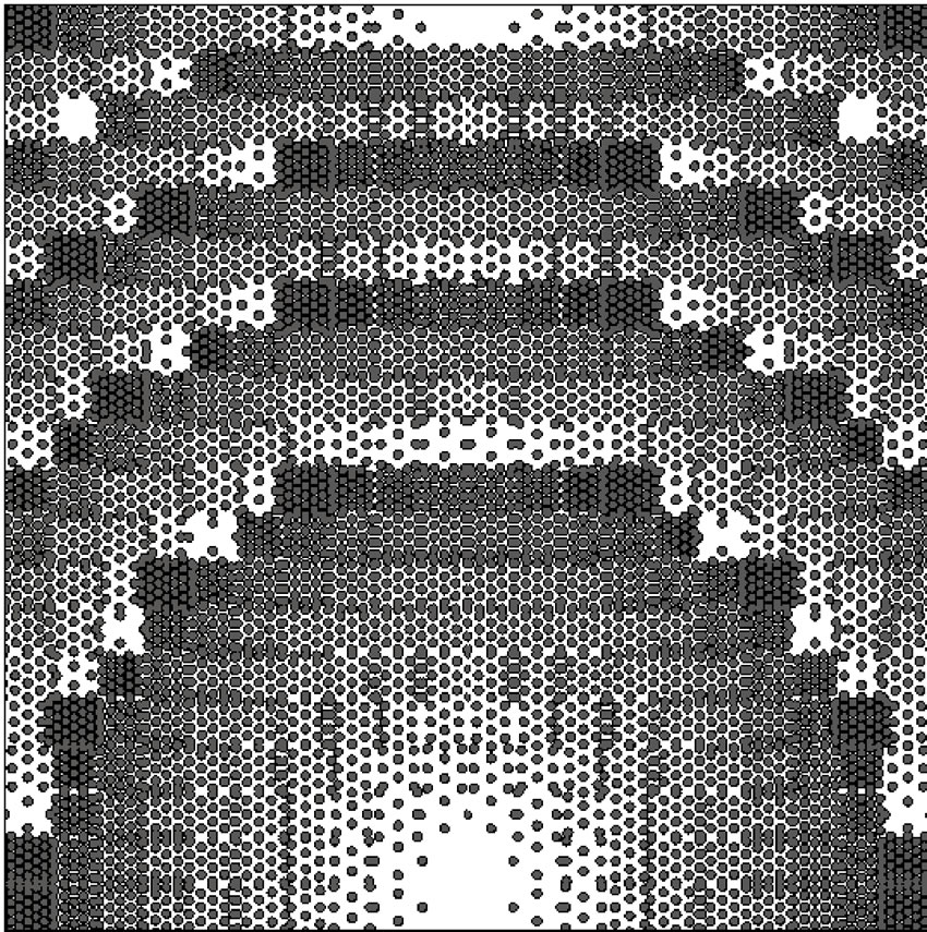 (b)
(b)
Figure 9. The design processes of 25˚ off broadside perforated reflect-array. (a) The required phase shifts of elements and corresponding  values; (b) The geometry of the designed perforated substrate.
Figure 10 shows the patterns on the E-plane. Note that the beams are 25˚ off broadside, and they achieve peak gain of 24.2 dB and 25.4 dB for perforated and equivalent substrates, respectively.
Figure 11 shows the directivity variations with frequency for both perforated and equivalent substrates. The corresponding 1-dB directivity bandwidths are 9.6%, 10.3%, respectively.
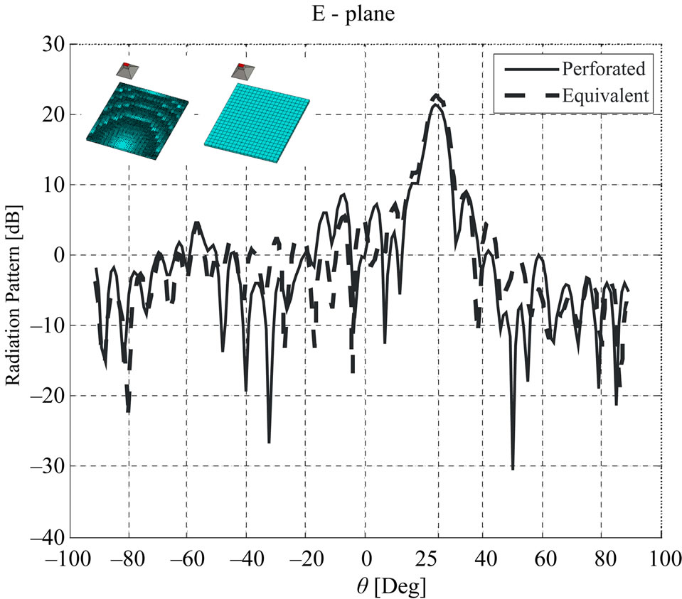
Figure 10. E-plane radiation patterns of 25˚ off broadside perforated and equivalent reflect-array.
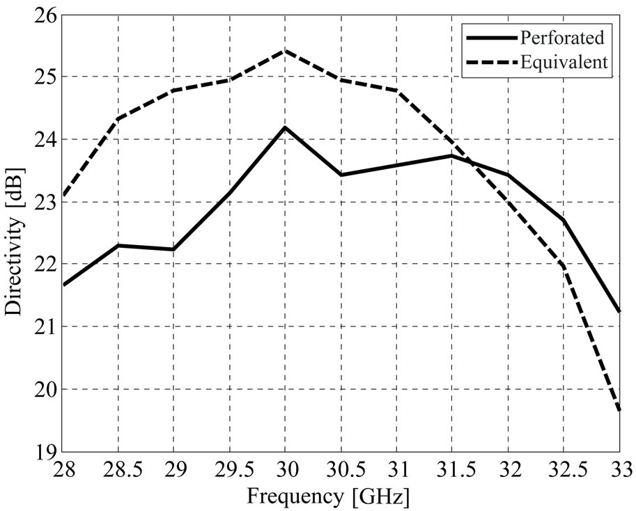
Figure 11. Directivity variations against frequency for 25˚ off broadside perforated and equivalent reflect-array.
5. Conclusions
A new reflect-array structure was presented, which consist of a perforated substrate with lattice of holes and a feed antenna. Perforated substrate with variable holes distribution was used to control the reflection phase. In the designing section, instead of analyzing the perforated element, the equivalent dielectric element was analyzed by a simple transmission line model, which has the distinct advantages of simplicity and rapidity in designing of such antennas. Then, after designing and finding the proper value of the effective electric permittivity for each element, the suitable holes distribution was obtained. Finally, the performance of proposed antenna was verified through presenting two examples at 30 GHz frequency.
REFERENCES
- N. Misran, R. Cahill and V. F. Fusco, “Reflection Phase Response of Microstrip Stacked Ring Elements,” Electronics Letters, vol. 38, no. 8, April 2002, pp. 356-357. doi:10.1049/el:20020257
- F.-C. E. Tasi and M. E. Bialkowski, “Design a 161-Element Ku-Band Microstrip Reflectarray of Variable Size Patches Using an Equivalent Unit Cell Waveguide Approach,” IEEE Transactions on Antennas and Propagation, October 2003, vol. 51, no. 10, pp. 2953-2962. doi:10.1109/TAP.2003.818001
- M. R. Chaharmir, J. Shaker and H. Legay, “Broadband Design of a Single Layer Large Reflectarray Using Multi Cross Loop Elements,” IEEE Transactions on Antennas and Propagation, vol. 57, no. 10, October 2009, pp. 3363-3366. doi:10.1109/TAP.2009.2029600
- J. A. Encinar, L. Datashvili, J. A. Zornoza, et al., “Dual Polarization Dual-Coverage Reflectarray for Space Applications,” IEEE Transactions on Antennas and Propagation, vol. 54, no. 10, 2006, pp. 2827-2837. doi:10.1109/TAP.2006.882172
- M. E. Bialkowski and K. H. Sayidmarie, “Investigations into Phase Characteristics of a Single-Layer Reflectarray Employing Patch or Ring Elements of Variable Size,” IEEE Transactions on Antennas and Propagation, vol. 56, no. 11, November 2008, pp. 3366-3372. doi:10.1109/TAP.2008.2005470
- M. H. Jamaluddin, R. Gillard, R. Sauleau, P. Dumon and L. Le Coq, “Reflectarray Element Based on Strip-Loaded Dielectric Resonator Antenna,” Electronics Letters, vol. 44, no. 11, May 2008, pp. 664-665. doi:10.1049/el:20080346
- M. G. Keller, J. Shaker, A. Petosa, A. Ittipiboon, M. Cuhaci and Y. M. M. Antar, “A Ka-Band Dielectric Resonator Antenna Reflectarray,” Proceedings of 30th European Microwave Conference, Paris, 3-5 October 2000, pp. 272-275. doi:10.1109/EUMA.2000.338713
- S. H. Zainud-Deen, Abd-Elhady, A. A. Mitkees and A. A. Kishk, “Design of Dielectric Resonator Reflectarray Using Full-Wave Analysis,” Proceedings of National Radio Science Conference, New Cairo, 17-19 March 2009, pp. 1-9.
- CST-Microwave Studio, “User’s Manual,” ®4, 2002.
- R. Chair, A. A. Kishk and K. F. Lee, ”Experimental Investigation for Wideband Perforated Dielectric Resonator Antenna,” Electronics Letters, vol. 42, no. 3, February 2006, pp. 137-139. doi:10.1049/el:20063987
- M. Khalaj-Amirhosseini, “Analysis of Lossy Inhomogeneous Planar Layers Using Taylor’s Series Expansion,” IEEE Transactions on Antennas and Propagation, vol. 54, no. 1, January 2006, pp. 130-135. doi:10.1109/TAP.2005.861577
- M. Bozzi, S. Germani and L. Perregrini, “Performance Comparison of Different Element Shapes Used in Printed Reflectarrays,” IEEE Antennas and Wireless Propagation Letters, vol. 2, No. 14, 2003, pp. 219-222. doi:10.1109/LAWP.2003.819687
- D. M. Pozar, S. D. Targonski and H. D. Syrigos, “Design of Millimeter Wave Microstrip Reflectarrays,” IEEE Transactions on Antennas and Propagation, vol. 45, no. 2, February 1997, pp. 287-296. doi:10.1109/8.560348