Smart Grid and Renewable Energy
Vol.4 No.2(2013), Article ID:32181,14 pages DOI:10.4236/sgre.2013.42021
Significance of Storage on Solar Photovoltaic System —A Residential Load Case Study in Australia
![]()
Central Queensland University, Power and Energy Centre, Institute for Resources Industries and Sustainability, Rockhampton, Queensland 4702, Australia.
Email: m.arif@cqu.edu.au
Copyright © 2013 Mohammad T. Arif et al. This is an open access article distributed under the Creative Commons Attribution License, which permits unrestricted use, distribution, and reproduction in any medium, provided the original work is properly cited.
Received November 28th, 2012; revised January 10th, 2013; accepted January 17th, 2013
Keywords: Storage; Photovoltaic; Residential Load; GHG; NPC; COE
ABSTRACT
Energy storage is an essential part in effective utilization of Renewable Energy (RE). Most RE sources cannot provide constant energy supply and introduce a potential unbalance in generation and demand, especially in off-peak periods when RE generates more energy and in peak period when load demand rises too high. Storage allows intermittent sources like solar Photovoltaic (PV) to address timely load demand and adds flexibility in load management. This paper analyses the significance of storage for residential load considering solar PV as RE generator. The significance of storage was evaluated in off-grid or stand alone and grid connected configurations. Moreover it outlined the significance of storage in terms of environment and economics by comparing the Renewable Fraction (RF), Greenhouse Gas (GHG) emission, Cost of Energy (COE) and Net Present Cost (NPC). Investigation showed that storage has positive influences on both (off-grid and grid connected) configurations by improving PV utilization. It was found that in grid connected configuration storage reduced 46.47% of GHG emission, reduced COE, NPC and improved RF compared to the system without storage.
1. Introduction
Storage system stores excess energy and releases stored energy when load demand goes high; it also minimizes the intermittent nature of solar energy. Storage offers substantial added values to the energy sector. Storage can improve electric grid system reliability, efficiency and flexibility by using it for frequency regulation [1]. Storage also stabilizes the cost of electricity and helps to reduce Greenhouse Gas (GHG) emission [2]. Fast response storage such as batteries, flywheels, and compressed air is as effective as conventional generation for the supply of regulation services [3]. However the use of storage depends on the load demand and generated electricity from RE sources. Natural factors limit solar PV to generate electricity according to the load demand. This study considered typical residential load in Australia to investigate the significance of storage. Residential solar PV system is very popular both in metropolitan area and regional areas in Australia and worldwide. Moreover Australian Government added carbon tax and provided rebates for residential solar PV projects to make RE popular to general people. However this home based solar PV systems are unable to meet the resident’s desire as presently installed systems are mostly without storage that are unable to provide electricity during night and cloudy days. Therefore for effective solar PV systems, storage should be integrated with it.
Load profile of a residential house varies according to the residents work time pattern. In the Capricornia region of Rockhampton in Australia, the working nature of the residents of Kawana suburb is such that most of the residents start work between 7:00 AM to 8:00 AM and return home between 5:00 PM to 6:00 PM during weekdays. Overall load demand on distribution network is very high in the evening and also in the morning however the residential solar PV generates electricity mostly during the working period which is of minimum use for the residents. Considering this scenario, this paper investigates how storage can improve this situation and help residential solar PV to support most of the time. Significance of storage is demonstrated in this paper by evaluating the benefit of storage in terms of environmental and economic perspective.
2. Background
Every kWh of electricity from conventional sources can be replaced by RE which eventually can reduce overall GHG emission. In Australia, Government’s Mandatory Renewable Energy Target (MRET) is to ensure 20% electricity or additional 45,000 GWh from RE sources by 2020 [4-6]. Moreover national GHG emission target is 60% below 2000 level by 2050 [5]. According to the National GHG inventory (Kyoto protocol accounting framework), energy sector is the major contributor to the GHG emission [7]. It is found that Energy sector alone contributes 62.71% of GHG emission in Queensland and overall 73.93% in Australia [5].
Many studies explained the effectiveness of RE in replacing fossil-fuel to produce electricity. Compared to most other countries, Australia’s solar resource is equal to world’s best. Annual average solar exposure is greater than 2200 kWh/m2/year [8]. Recent PV collectors can track the sun to allow collection of a greater amount of energy. However the main drawbacks of solar PV are diurnal solar cycle, irregular solar radiation, seasonal variation and geographic locations. Moving clouds can produce fast and short irradiance, which causes voltage and power fluctuations at the Point of Common Coupling (PCC) and can introduce feeder losses [9,10]. The fluctuation level of solar energy is such that it can drop energy in very short time as shown in Figure 1 [11].
PV systems are a small part of present electricity infrastructure and have little effect on the overall power quality or reliability of grid power. However, when PV penetration reaches sufficiently high level, the intermittent/transient nature of PV generation begins to have noticeable negative effects on the entire grid [12]. Grid energy storage is mostly important for matching supply and demand over 24 hours period of time. Storage systems and storage integrated PV applications are described in the next section.
2.1. Storage Systems
Storage improves the capacity of RE systems. The ability
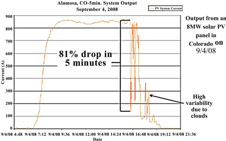
Figure 1. Variability nature of solar energy [11].
to store large amounts of energy would allow electrical utilities to have greater flexibility in their operation, because with this option the supply and demand do not have to be matched instantaneously [13]. From different form of energy storage systems, Pumped hydro, Compressed Air Energy Storage (CAES), Thermal Energy Storage (TES), Superconducting Magnetic Energy Storage (SMES), Flywheel, Hydrogen, Capacitors and Batteries are used in different renewable energy conservation process. Advantage and limitations of various storage systems are listed in Table 1 [14-19]. Although large scale storage is still expensive but significant research is underway for inexpensive & efficient large scale storage systems [20] suitable for large scale RE applications.
2.2. Storage Integrated PV Applications
PV arrays can be considered for different kinds of Application i.e. from small stand-alone to large scale gridconnected solar power plants, also from ground to roof installation or building integrated photovoltaic application. Stand-alone solar power system is suitable for applications in remote areas, which is located far away from utility grid. Grid-connected solar PV application interacts with utility grid by transforming DC to AC by an inverter. AC electricity is consumed by AC home appliances and excess energy stored in storage for home-use, also can be sold back to the utility.
A recent study on high penetration of PV on present grid mentioned that energy storage is the ultimate solution for allowing intermittent sources to address utility base load needs [12]. Storage integrated PV systems should be beneficial in operational, financial and environmental perspective. Therefore a model has been developed to assess economical & financial benefit of storage with solar PV and explained in the next section.
3. Model Evaluation
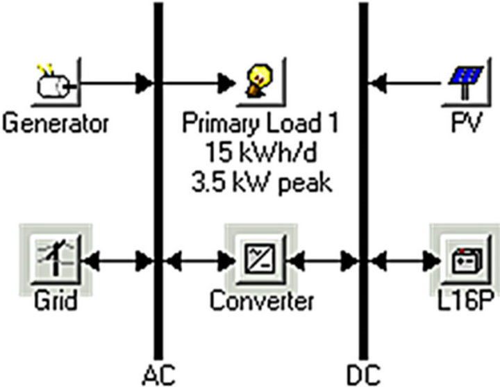
Simulation was performed to identify the optimized configuration of PV with storage, grid or diesel generator for the residential load. Model was developed using HOMER optimization tool as shown in Figure 2. The model was evaluated considering the project life time of 20 years.
 (a)
(a) (b)
(b)
Figure 2. Simulation model configuration: (a) Off-grid configuration; (b) Grid-connected configuration.
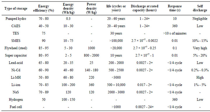
Table 1. Energy storage systems [14-19].
The performance matrices of the optimized model, required data, component costs and considerations are explained in following subsections.
3.1. Performance Matrices
The performance matrices considered are Net Present Cost (NPC), Cost of Energy (COE) as economical factor, Renewable Fraction (RF) and Greenhouse Gas (GHG) emission as environmental factor which compared in offgrid and grid connected configurations.
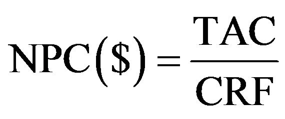
Net Present Cost (NPC): NPC is the present value of all costs over its lifetime minus the present value of all the revenue that it earns over its lifetime. Costs includes capital cost, replacement cost, operation and maintenance (O&M) costs, fuel cost, emission penalties and cost of buying power from the grid. Revenue includes salvage value and grid sales revenue. NPC is the main economic output of the model and ranked all optimized systems according to total NPC as represented [21,22] by Equation (1):
 (1)
(1)
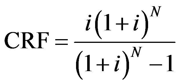
where TAC is the total annualized cost (which is the sum of the annualized costs of each system component). The capital recovery factor (CRF) is given by Equation (2):
 (2)
(2)
where N denotes number of years and i means annual real interest rate (%). Model considered nominal interest rate. The overall annual interest rate considered as 6%.
Cost of Energy (COE): It is the average cost per kWh of useful electrical energy produced by the system. It can be calculated by dividing the annualized cost of producing electricity by the total useful electric energy production and represented in [21] by Equation (3):
 (3)
(3)
where Cann,tot is total annualized cost of the system ($/yr), Eprim,AC is AC primary load served (kWh/yr), Eprim,DC is DC primary load served (kWh/yr), Edef is deferrable load served (kWh/yr) and Egrid,sales is total grid sales (kWh/yr).
Emission: Emission is widely accepted and understood environmental index. Greenhouse gases (CO2, CH4, N2O, HFCs, PFCs, SF6) are considered one of the main causes for global warming. In addition SO2 is another pollutant gas released by coal fired energy system. Emission is measured as yearly emission of the emitted gases in kg/year and emissions per capita in kg/kWh. It is considered as input in the model when calculating the other O&M cost. The other O&M cost is the sum of system fixed O&M cost, penalty for capacity shortage and penalty for emissions of pollutants. It was represented in [21] as shown in Equation (4):

 (4)
(4)
where Com,fixed is system fixed O&M cost ($/yr), Ccs is the penalty for capacity shortage ($/yr) and Cemission is the penalty for emission ($/yr).
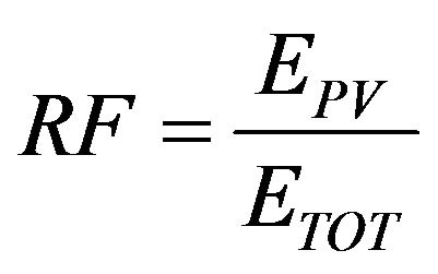
Renewable Fraction (RF): RF is the total annual renewable energy production divided by the total energy production. A greater value of this fraction means the greater renewable energy generated. RF can be calculated by Equation (5) [23]:
 (5)
(5)
where EPV and ETOT are the energy generated by photovoltaic and total energy generated respectively.
3.2. Model Data
Residential load data of Rockhampton (a regional subtropical town based in Queensland, Australia) was used in this analysis. This regional site has good solar radiation history and most the residents working nature is monotonous and many houses have roof top PV facility. Solar radiation data was collected from Bureau of Meteorology [24] for the site location. All required system components are discussed in the following sub-sections.
3.2.1. Data Collection
A three bed room house daily load in Capricornia region of Rockhampton was estimated as 15.0 kWh/day. This was done by multiplying the power rating of all the home appliances by the number of expected operating hours on an average day to obtain daily load in watt-hour (Wh).
Table 2 shows the list of electrical appliances used in a 3 bed room house and calculated daily average electricity consumption.
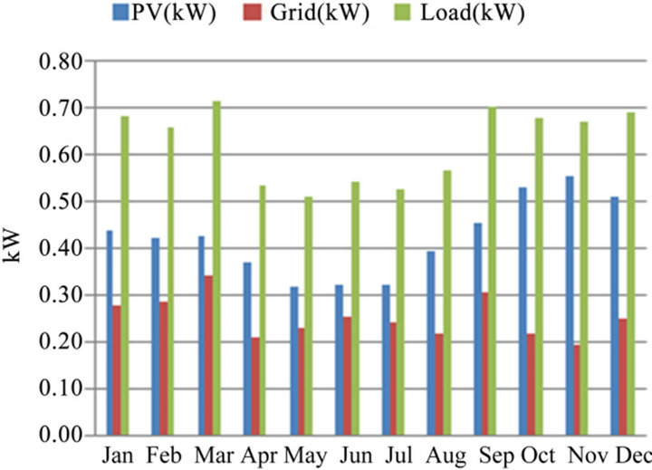
This 3 bed room residential load was considered for the analysis; therefore yearly electricity consumption becomes 5475 kWh/yr. For grid connected household appliances daily average load can also be obtained from monthly utility bills. According to Ergon Energy (utility operator in Queensland, Australia) electricity billing information, the daily average residential electricity consumption is 15.7 kWh/day [25]. Providing estimated hourly load data in the model, the daily load profile with seasonal variation is as shown in Figure 3. Daily electricity consumption pattern shows that 08:00 - 09:00 hrs and 18:00 - 22:00 hrs have the peak demand however from 18:00 - 19:00 hrs has the super peak load demand.
The load profile in Figure 3 shows the daily consumption pattern and the maximum consumption period is 6:00 PM to 10:00 PM and in the morning 8:00 AM to 9:00 AM.
3.2.2. Solar Radiation and Power from PV Array
Solar radiation varies with time and season. In Australia yearly average sunlight hours varies from 5 to 10 hours/ day and maximum area is over 8 hours/day [24] and in Rockhampton solar radiation varies from 8 to 9 hrs/day. Therefore to capture maximum RE and to provide electricity at night or cloudy day, a storage system should be incorporated.

Figure 3. Daily electric load demand in each month.
Hourly solar radiation data was collected from Bureau of Meteorology [24] for the year 2009 and 2010 of station No. 039083 for the location of Rockhampton Aero Weather Station (−23.3753˚N, 150.4775˚E) which is at 10.4 m above the mean sea level. Daily average solar radiation in Capricornia region of Rockhampton city is as shown in Figure 4. It is found that annual average solar
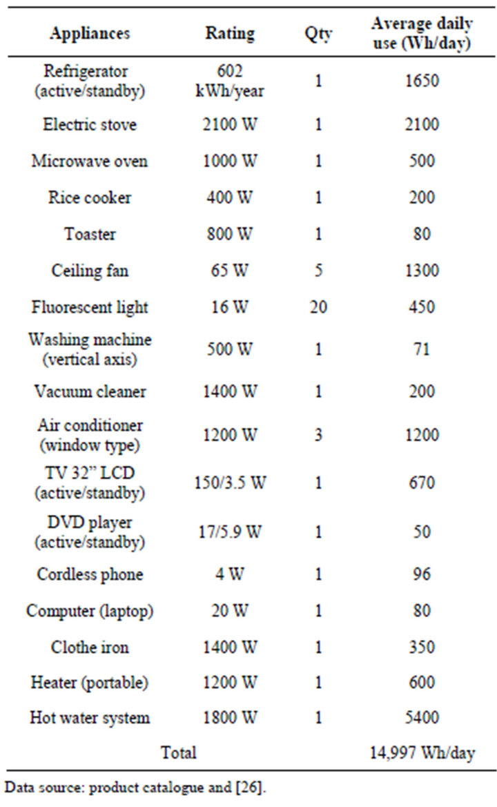
Table 2. Electrical appliances of a three bedroom house & daily average load.
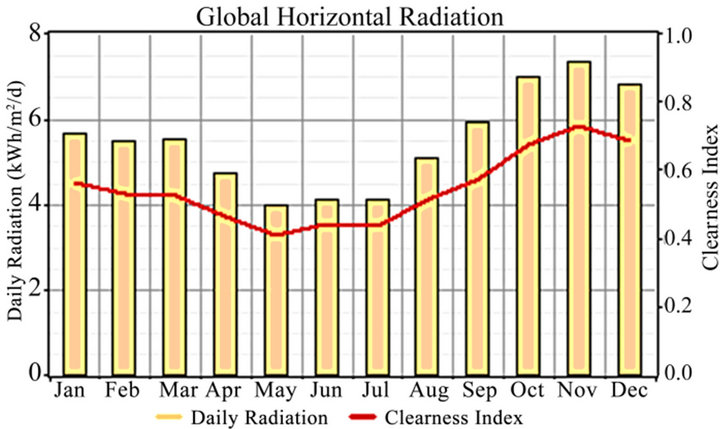
Figure 4. Daily average solar radiation in Rockhampton.
radiation is 5.48 kWh/m2/day and the lowest monthly average solar radiation 4 kWh/m2/day in May.
PV array can be modeled as a device that produces DC electricity in direct proportion to the global solar radiation. Therefore, the power output of the PV array can be calculated using Equation (6) [27,28].
 (6)
(6)
where YPV—rated capacity of PV array which means power output under standard test conditions [kW]. fPV— PV de-rating factor [%]. GT—solar radiation incident on PV array in current time step [kW/m2]. GT,STC—incident radiation under standard test conditions [1 kW/m2]. αP— temperature coefficient of power [%/˚C]. TC—PV cell temperature in current time step [˚C]. TC,STC—PV cell temperature under standard test conditions [25˚C]. Performance of PV array depends on de-rating factors like temperature, dirt and mismatched modules.
3.2.3. Storage
Battery is one of the fast response storage systems. For this analysis Trojan L16P Battery (6 V, 360 Ah) at 24 V DC system voltage was used. The efficiency of this battery is 85%, minimum state of charge 30%. Model considered PV array includes the battery charge controller with efficiency 95% and PV de-rating factor of 90% therefore overall charging efficiency considered (95 × 90)% = 85.5%.
Battery dispatch: Two battery dispatch strategy explained [29], named “load following” and “cycle charging”. In load following strategy, a generator produces only enough power to serve the load, battery charging and supporting deferrable load depends on renewable power sources. In cycle charging strategy, whenever a generator operates it runs at its maximum rated capacity, charging the battery bank with any excess electricity until the battery reaches the specified state of charge. Load following strategy was considered for this analysis for the better utilization of solar energy.
3.3. System Components and Costs
Table 3 lists the required system components with related costs in Australian currency. PV array, battery charger, inverter, deep cycle battery, generator and grid electricity cost are included for the analysis. It was found that 1.52 kW PV array with inverter price is $3599 [30], also it was found that 1.56 kW PV array with inverter price is $4991 [31]. However model considered PV array includes the battery charger therefore inverter costs considered separately. SMA Sunny Boy Grid Tie Inverter (7000 Watt, SB7000US) price is $2823 [32], however Sunny Boy 1700 W inverter price is $699 [33] and in
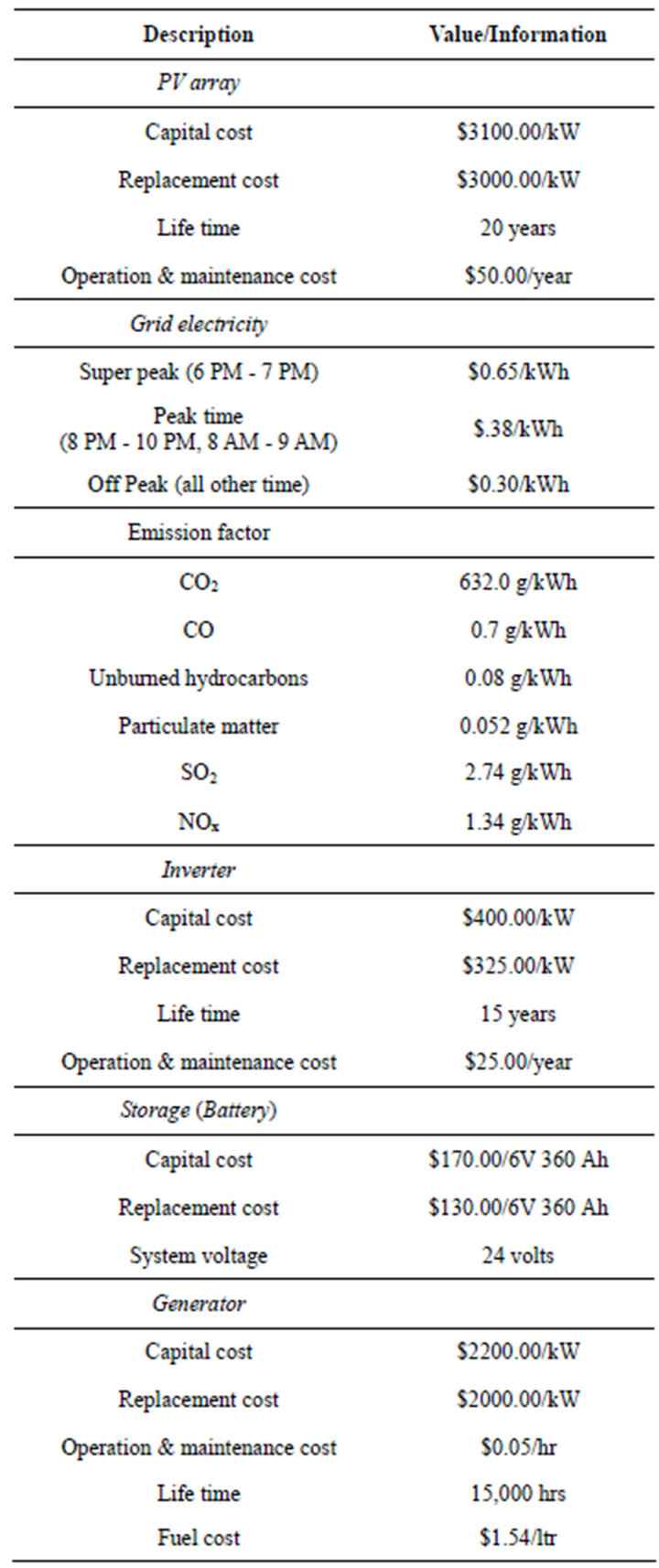
Table 3. Technical data and study assumptions.
verter efficiency was considered 94%.
Grid electricity cost in Rockhampton was found from Ergon Energy’s electricity bill and for Tariff-11 it was $0.285/kWh (including GST & service). However carbon tax at the rate of $23 for every ton of emission increases the electricity bill as well as the cost of conventional energy sources, therefore off-peak electricity cost is considered as $0.30/kWh for this analysis. Trojan T-105 6 V, 225 AH (20 HR) flooded Lead-acid battery price is $124.79 [34]. Fuel cost for generator is considered at the available price in Rockhampton. Table 3 shows the unit cost of each component.
The significance of storage was analyzed from the optimization result and evaluated environmental and economical advantages of storage in off-grid and grid-connected configurations in six different cases.
Ÿ Configuration-1: Off-grid Configuration [as shown in Figure 2(a)]
Ÿ Case-1: Diesel Generator only;
Ÿ Case-2: PV with Diesel Generator;
Ÿ Case-3: PV with Storage and Diesel Generator.
Ÿ Configuration-2: Grid-connected Configuration [as shown in Figure 2(b)]
Ÿ Case-1: Grid only;
Ÿ Case-2: PV with Grid and Diesel Generator;
Ÿ Case-3: PV with Storage, Grid and Diesel Generator.
4. Results and Discussion
Model was analyzed in six different cases and the output of the optimized model is explained below:
Configuration—1
Case 1. Diesel Generator in off-grid configuration:
In this configuration, total load of 5475 kWh/yr were supported only by 10 kW diesel generator which consumed enough fuel (8371 L/yr) and emitted significant amount of pollutant gas to the air. Generator requires frequent maintenance and fuel cost is also high, therefore NPC was high. COE also found very high, which is $5.238/kWh. This case configuration is the costliest and environmentally most vulnerable.
Case 2. PV with Diesel Generator in off-grid configuration:
In this configuration, solar PV used to support residential load and used diesel generator as backup power. To meet 5475 kWh/yr load demand, 12 kW PV system was used with 5 kW inverter and 10 kW diesel generator. It was found that, although PV generates electricity more than the total load demand but could not meet the load demand during night.
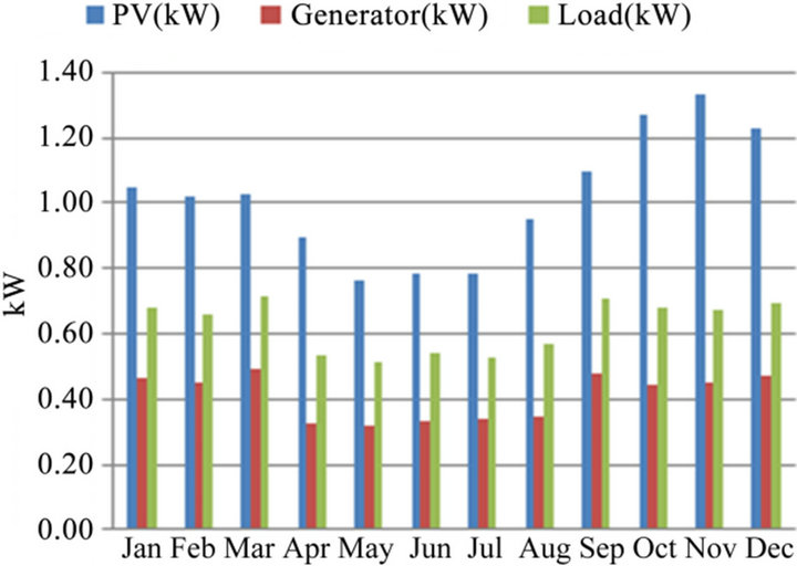
Total 12,489 kWh/yr of electricity was generated by PV and diesel generator, where 3581 kWh/yr or 29% was from diesel generator and 8908 kWh/yr or 71% was from PV array but most of the energy from PV array was wasted. Diesel generator directly supports 65.40% of load and PV array supports only 1894 kWh/yr or 34.60% of load through inverter. Therefore a significant amount of electricity from PV array was wasted and the excess electricity was 6893.10 kWh/yr or 55.19% of total electricity production but compared to the total PV array production the wasted electricity was 77.38%. Storage could reduce this great amount of electricity loss also could reduce the use of diesel generator.
Figure 5(a) shows the electricity generated from PV array and the diesel generator. Compared to the load demand, PV generates more electricity but PV was unable to meet timely load demand as shown in Figures 5(b)- (d). Figure 5(b) shows the daily electricity generated by PV array and shows that PV was unable to generate electricity in the morning and night. During morning and night, load demand was supported solely by diesel gen-
 (a)
(a) (b)
(b) (c)
(c) (d)
(d)
Figure 5. Configuration-1 Case-2 output: (a) PV and diesel generator output compared to load demand; (b) Electricity generated from PV array; (c) Electricity generated from diesel generator; (d) Inverter output.
erator as shown in Figure 5(c). Inverter converts only a fraction of PV generated DC electricity to AC according to the load demand as shown in Figure 5(d), therefore great amount of electricity simply wasted.
Case 3. PV with Storage and Diesel Generator in off-grid configuration:
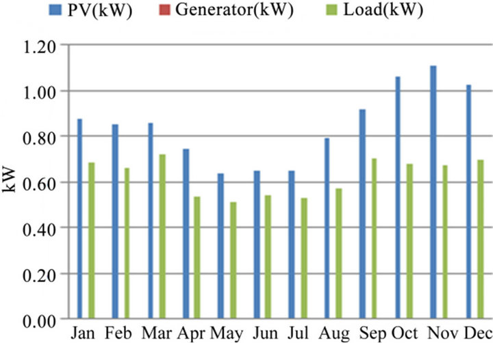
In this case, model adds battery as storage. This optimized model used 10 kW PV, 32 number of Trojan L16P battery (@ 6 V, 360 Ah) at 24 V DC system voltage, 1 kW diesel generator and 5 kW inverter to support the load of 5475 kWh/yr. This model configuration nearly shaded out the use of diesel generator and only 3 kWh/yr load was supported by diesel generator. It was found that, PV generates electricity more than the load demand and battery stored enough energy to support the load during morning and night.
Total 7427 kWh/yr of electricity was generated from PV array and diesel generator where diesel generator generates only 3.37 kWh/yr. PV array generates 7423 kWh/yr or 99.95% of total production. PV array with storage supports 5472 kWh/yr or 99.95% of load demand and diesel generator supports only 0.05% of load demand. AC load supported directly by PV array through inverter during day time and by stored energy in battery during morning & night time. Inverter converts 5821 kWh/yr of DC to 5472 kWh/yr of AC. Battery stored 4040 kWh/yr of energy and supplied 3477 kWh/yr to support the load. Battery stored 54.42% of PV generated energy and supported 63.50% of load while PV directly supports 36.44% of load. However still 1039 kWh/yr of excess energy generated by the PV array, i.e., 13.99% of total generated energy simply wasted which could be sold to the grid.
In this application scenario, utilization of inverter was better than earlier case scenario, because inverter not only converts the PV output but also converts stored energy from battery as shown in Figure 6(d) compared to Figure 5(d). Figure 6(a) shows the electricity generated from PV array, diesel generator compared to load demand. Diesel generator only used in March for a short time where load to PV output ratio is highest. Figure 6(b) shows the daily electricity generated by PV array and it is clear that PV array is unable to support load in the morning and night when battery supports the load as shown in Figure 6(c). It was found that battery SOC was from 30% to 100% in this case. However a moderate amount of energy was wasted in this case.
This system supports nearly 100% load demand by PV and battery therefore there is less emission which makes it environment friendly off-grid configuration.
Configuration—2
Case 1. Grid only configuration:
This is the present connection configuration for household electricity. Grid supplies the total load demand of 5475 kWh/yr. Grid electricity tariff varies with season, time and application [35,36]. In this grid connected configuration model, for residential load grid electricity cost was considered in 3 different price levels shown in Table 3. However it is mentioned earlier that currently available grid electricity cost for residential use is $0.285/kWh. Simulation result showed that average COE becomes $0.393/kWh. Grid electricity mainly comes from conventional sources therefore a good amount of pollutant gas emitted to the air.
Case 2. Grid connected PV with Diesel Generator:
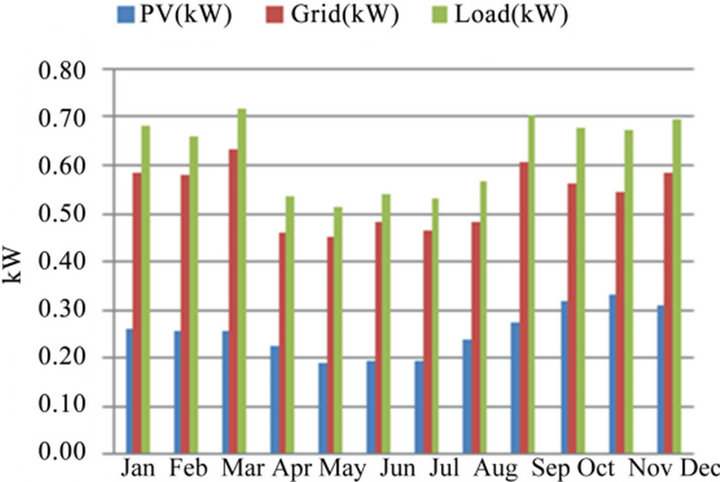
In this case diesel generator was shaded out as grid electricity was much cheaper. PV still contributed a reasonable portion of load demand. This optimized model used 3 kW PV with 5 kW inverter and grid supply. Total 6924 kWh/yr of electricity was generated where PV array generates 2227 kWh/yr or 32.16% of total production. Grid supplied 4697 kWh/yr i.e., 67.84% of total production or 85.79% of total load demand. PV array supported 778 kWh/yr or 14.21% of load demand, also 529 kWh/yr of PV array generated electricity was sold back to the grid. However 837 kWh/yr or 37.58% of PV generated electricity was wasted in timely demand mismatch which could be stored and supplied to the load.
Figure 7(a) shows total electricity production from PV and grid support compared to the load demand. It was found that PV generates electricity during day time and peak demand was met by grid supply therefore a significant amount of PV generated electricity was wasted as shown in Figure 7(b). In this application scenario, inverter was minimally utilized only during day time as shown in Figure 7(c).
Case 3. Grid connected PV with Storage and Diesel Generator:
In this case diesel generator was shaded out as overall generated electricity was much cheaper. PV array contributed a good portion of load demand with storage support. This case is very interesting compared to the earlier case that by only adding sufficient amount of storage it improved the contribution of PV array also made room for additional PV array to support the same total load. This optimized model used 5 kW PV with 12 number of L16P battery (@ 6 V, 360 Ah) at 24 V DC system voltage, 5 kW inverter and grid supply.
Total 5943 kWh/yr of electricity was produced where grid supplied 2232 kWh/yr or 37.55% of total production or 40.76% of total load demand. PV array produced 3712 kWh/yr which was 62.46% of total production. Battery stored 1860 kWh/yr or 50.11% of PV generated electricity and supported 1599 kWh/yr or 29.20% of total load demand. However PV array directly supported 1644 kWh/yr or 30.03% of load demand through inverter.
Figure 8(a) shows the electricity production from PV array and support from grid compared to load demand. PV cannot support load during morning and night as
 (a)
(a) (b)
(b) (c)
(c) (d)
(d)
Figure 6. Configuration-1 Case-3 output: (a) PV & Diesel generator output compared to load demand; (b) PV array output; (c) Battery state of charge (SOC); (d) Inverter output.
shown in Figure 8(b). Figure 8(c) shows the battery SOC and it shows that battery mostly utilized during peak demand time in the evening which is evident in Figure 8(d) as inverter was used to convert stored energy.
Therefore storage helped in supporting load in peak demand time when grid electricity is costly. Figures 8(c) and (d) showed that both these components (Battery and Inverter) were not completely utilized therefore more PV array could utilize these components to sell extra electricity to the grid and can reduce the overall cost of the system.
Summary:
From the discussed result above it was found that storage improved RE share in load support and reduced loss of energy as shown in Table 4. However the storage influences on the performance indexes, these are explained in Findings section.
Findings
The optimization was done in two configuration categories and 3 cases in each configuration and 4 different factors were compared in each case. These factors are GHG
 (a)
(a) (b)
(b) (c)
(c)
Figure 7. Configuration-2 Case-2 output: (a) PV & grid output compared to load demand; (b) PV array output; (c) Inverter output.
& Pollutant gas emission, RF, COE and NPC. The findings of these factors are explained below:
GHG & pollutant gas emission:
Optimized model results in different cases showed that in both configurations storage in case 3 helped in reducing GHG & other pollutant gas emission as shown in Figure 9.
Renewable Fraction (RF):
Results showed that in both configurations storage improved RE production. Figure 10 shows that Storage helps in increasing RF.
Cost of energy:
Results showed that generator only configuration was most costly therefore COE was very high. However Storage sharply reduced the COE in off-grid configuration. Although overall grid only electricity in case-1 was little cheaper but storage still helped in reducing the COE by improving the PV penetration as shown in Figure 11 where in case-2 COE was $0.579/kWh and in case-3 COE became $0.556/kWh.
Net Present Cost (NPC):
Results showed that in off-grid configuration, PV with diesel generator in case-2, a good amount of electricity was supplied from PV array which reduced NPC. Storage further accelerated the share of RE and reduced NPC as shown in case-3 in Figure 12.
In grid-connected configuration although NPC increased in case-2 while PV shared the load but in case-3 storage improved PV participation and reduced NPC as shown in Figure 12.
Payback period:
Payback is the number of years in which the cumulative cash flow switches from negative to positive. For this analysis it was found by comparing PV, storage, grid system with PV and grid base system. Payback period requires the collection of annualized cost of the system which are calculated by summing the capital cost, O&M cost, operating cost, fuel cost and replacement cost for each year. Annualized costs are then subtracted from each other for each consecutive year which provides savings
 (a)
(a) (b)
(b) (c)
(c) (d)
(d)
Figure 8. Configuration-2 Case-3 output: (a) PV & grid output compared to load demand; (b) PV array output; (c) Battery state of charge (SOC); (d) Inverter output.

Table 4. Model result and significance of storage.
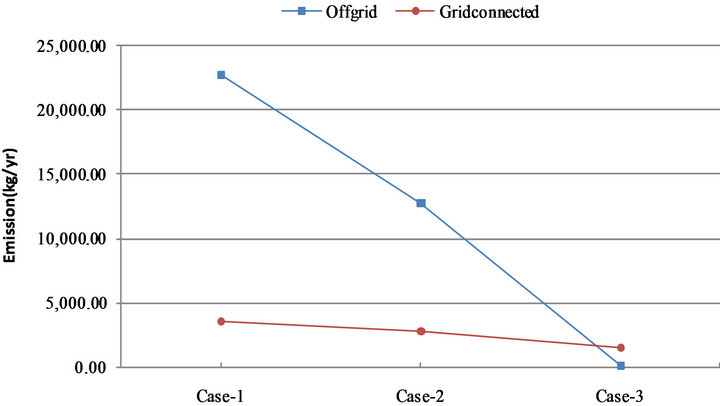
Figure 9. GHG emission in different case configurations.
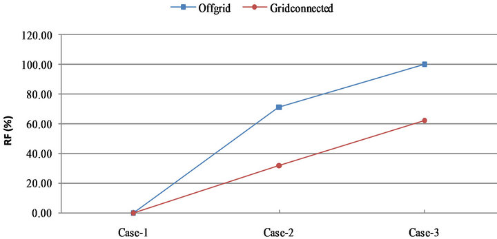
Figure 10. RF in different case configurations.
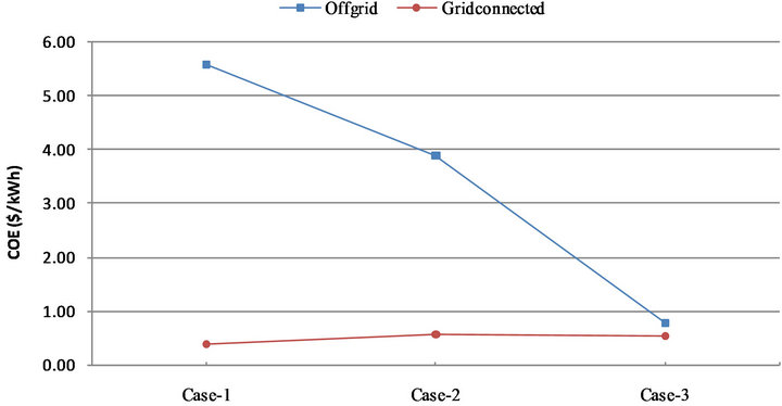
Figure 11. COE in different configurations.

Figure 12. NPC in different configurations.
or loss for each year. Result showed that the cost of storage returned in 4.9 years considering the project life of 20 years as shown in Figure 13. In Australia solar bonus scheme awards the price of electricity fed into the grid from PV systems at a rate of $0.44/kWh [37,38] this ensures that the payback period is much shorter in Australia.
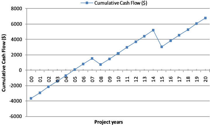
Figure 13. Storage pay back period.
5. Conclusions
Storage integrated PV system was analyzed for a residential load in Rockhampton, Queensland, Australia in off-grid and grid connected configurations. Analysis was conducted to observe the storage influences over the GHG emission, RF, COE and NPC indexes. It was found that storage greatly influenced the improvement of RE utilization.
It was clear from the analysis that storage helped significantly in reducing GHG & other pollutant gas emission, and reduced COE, improved RF also reduced the NPC. Comparing PV integrated system with and without storage, it was found that in the grid connected configuration, storage reduced 46.47% of GHG and pollutant gas emission and in stand-alone system it reduced 99.97%. In grid connected configuration, storage integrated PV system improved RF 93.78% and in standalone system 40.17% compared to without storage condition. Storage reduced COE by 3.97% in grid connected configuration and 79.45% in standalone configuration. Similarly storage reduced NPC by 13.76% in grid connected configuration and 79.46% in standalone configuration. Moreover storage integrated PV in grid connected configurations has reasonable payback period and the cost of storage returns in very short time. Therefore storage has a positive influence in environmental and economic indexes either in off-grid or grid-connected configurations.
Australia has comparatively good solar radiation rate which shows such impressive results in all four indexes. This result also identifies the scope of maximizing the utilization of RE by using storage to meet residential load demand.
REFERENCES
- R. Fioravanti, “The Importance of Energy Storage for System Regulation,” 2012. http://www.elp.com/index/display/article-display/2450936349/articles/utility-automation-engineering-td/volume-14/issue-10/features/the-importance_of.html
- KEMA, “Large-Scale Electricity Storage,” 2012. http://www.kema.com/services/consulting/etd/es/large-scale-storage.aspx
- KEMA, “Benefits of Fast-Response Storage Devices for System Regulation in ISO Markets,” 2012. http://www.kema.com/Images/FastResponseStorage11-25-08SCREEN.pdf
- DoRET, “Energy in Australia 2010,” Department of Resources, Energy and Tourism, Australia, 2010.
- Queensland-Government, “The Queensland Renewable Energy Plan, a Clear Energy Future for Queensland,” 2009. http://www.cleanenergy.qld.gov.au/queensland_renewable_energy_plan.cfm
- REN21, “Renewables 2010,” Global Status Report, 2010. http://www.ren21.net/Portals/97/documents/GSR/REN21_GSR_2010_full_revised%20Sept2010.pdf
- DCC, “National Greenhouse Gas Inventory—Accounting for the KYOTO Target May 2009,” Department of Climate Change, Australian Government, 2009. http://www.climatechange.gov.au/climate-change/~/media/publications/greenhouse-report/national-greenhouse-gas-inventory-pdf.ashx
- Energy Research Institute, “Australian Sustainable Energy, Zero Carbon Australia Stationary Energy Plan,” 2010. http://www.energy.unimelb.edu.au/
- R. Albarracin and H. Amaris, “Power Quality in Distribution Power Networks with Photovoltaic Energy Sources,” IEEE Proceedings of the International Conference on Environment and Electrical Engineering, Karpacz, 10-13 May 2009.
- R. K. Varma, M. Salama, R. Seethapathy and C. Champion, “Large-Scale Photovoltaic Solar Power Integration in Transmission and Distribution Networks,” IEEE Power & Energy Society General Meeting, Calgary, 26-30 July 2009, pp. 1-4. doi:10.1109/PES.2009.5275321
- S. Rahman, “The Smart Grid, Its Opportunities and Challenges,” Asia-Pacific Power & Energy Engineering Conference, Chengdu, 29 March 2010.
- C. J. Hanley, D. T. Ton, G. H. Peek and J. D. Boyes, “Solar Energy Grid Integration Systems—Energy Storage (SEGIS-ES),” Sandia Report, SAND2008-4247, 2008.
- L. L. Grigsbay, “The Electric Power Engineering Handbook,” CRC Press, New York, 2001.
- S. Vazquez, S. M. Lukic, E. Galvan, L. G. Franquelo and J. M. Carrasco, “Energy Storage Systems for Transport and Grid Applications,” IEEE Transactions on Industrial Electronics, Vol. 57, No. 12, 2010, pp. 3881-3895. doi:10.1109/TIE.2010.2076414
- M. T. Arif, A. M. T. Oo and A. B. M. Shawkat Ali, “Estimation of Energy Storage and Its Feasibility Analysis, Energy Storage—Technologies and Applications,” A. Zobaa, Ed., 2013. http://www.intechopen.com/books/energy-storage-technologies-and-applications/estimation-of-energy-storage-and-its-feasibility-analysis
- F. Rahman, S. Rehman and M. A. Abdul-Majeed, “Overview of Energy Storage Systems for Storing Electricity from Renewable Energy Sources in Saudi Arabia,” Renewable and Sustainable Energy Reviews, Vol. 16, No. 1, 2012, pp. 274-283. doi:10.1016/j.rser.2011.07.153
- M. Beaudin, H. Zareipour, A. Schellenberglabe and W. Rosehart, “Energy Storage for Mitigating the Variability of Renewable Electric Sources: An Updated Review,” Energy for Sustainable Development, Vol. 14, No. 4, 2010, pp. 302-314. doi:10.1016/j.esd.2010.09.007
- F. Diaz-Gonzalez, A. Sumper and O. Gomis-Bellmunt, “A Review of Energy Storage Technologies for Wind Power Applications,” Renewable and Sustainable Energy Reviews, Vol. 16, No. 1, 2012, pp. 2154-2171. doi:10.1016/j.rser.2012.01.029
- I. Hadjipaschalis, A. Poullikkas and V. Efthimiou, “Overview of Current and Future Energy Storage Technologies for Electric Power Applications,” Renewable and Sustainable Energy Reviews, Vol. 13, No. 6-7, 2009, pp. 1513- 1522. doi:10.1016/j.rser.2008.09.028
- C. Wessells, “Nanoparticle Electrode for Batteries Could Make Large-Scale Power Storage on the Energy Grid Feasible,” Stanford University News, 2011. at:http://news.stanford.edu/news/2011/november/longlife-power-storage-112311.html
- HOMER, “Analysis of Micro Powersystem Options.” https://analysis.nrel.gov/homer/
- G. J. Dalton, D. A. Lockington and T. E. Baldock, “Feasibility Analysis of Stand-Alone Renewable Energy Supply Options for a Large Hotel,” Renewable Energy, Vol. 33, No. 7, 2008, pp. 1475-1490. doi:10.1016/j.renene.2007.09.014
- A. N. Celik, “Techno-Economic Analysis of Autonomous PV-Wind Hybrid Energy Systems Using Different Sizing Methods,” Energy Conversion and Management, Vol. 44, No. 12, 2003, pp. 1951-1968. doi:10.1016/S0196-8904(02)00223-6
- BoM, Bureau of Meteorology, Australian Government. http://reg.bom.gov.au/
- ErgonEnergy, “Understanding Your Electricity Bill, Information about Average Consumption,” 2012. http://www.ergon.com.au/your-business/accounts--and--billing/understanding-your-bill
- G. M. Masters, “Renewable and Efficient Electric Power Systems,” John Wiley & Sons, Inc., Hoboken, 2004. doi:10.1002/0471668826
- T. Lambert, “How HOMER Calculates the PV Array Power Output,” Homer Help File, 2007. http://homerenergy.com/
- P. N. John, A. M. A. Haidar and M. Shawal, “Optimal Configuration Assessment of Renewable Energy in Malaysia,” Renewable Energy, Vol. 36, No. 2, 2011, pp. 881-888. doi:10.1016/j.renene.2010.07.024
- D. C. Barley and B. C. Winn, “Optimal Dispatch Strategy in Remote Hybrid Power Systems,” Solar Energy, Vol. 58, No. 1, 1996, pp. 65-79.
- PV-Price, “Sun Solar System,” 2012. www.sunsolarsystem.com.au
- PV-Price, “Goodhew Electrical and Solar,” 2012. http://www.goodhewsolar.com.au/customPages/goodhew-electrical-%26-solar-offers-homeowners-the-most-affordable-quality-solar-systems-on-the-market.?subSiteId=1
- Inverter-Cost, “SMA Sunny Boy Grid tie Inverter 7000 W SB7000US Price,” 2012. http://www.google.com/products/catalog?hl=en&q=sunny+boy+grid+tie+inverter+price&gs_sm=3&gs_upl=2378l7840l1l8534l11l10l0l1l1l0l223l2055l0.3.7l11l0&bav=on.2,or.r_gc.r_pw.,cf.osb&biw=1680&bih=831&um=1&ie=UTF-8&tbm=shop&cid=10871923140935237408&sa=X&ei=z0g6T-T0LayziQfnkZGQCg&ved=0CGkQ8wIwAQ
- Inverter-Cost, “SMA Sunny Boy 1700 Price,” 2012. http://www.solarmatrix.com.au/special-offers/sunny-boy-1700?ver=gg&gclid=CMO0gIOzna4CFYVMpgod7T1OHg
- ALTE-Store, “Battery Price, Trojan T-105 6 V, 225 AH (20HR) Flooded Lead Acid Battery.” http://www.altestore.com/store/Deep-Cycle-Batteries/Batteries-Flooded-Lead-Acid/Trojan-T-105-6V-225AH-20HR-Flooded-Lead-Acid-Battery/p1771/
- ErgonEnergy, “Electricity Tariffs and Prices.” http://www.ergon.com.au/your-business/accounts--and--billing/electricity-prices
- RedEnergy, “Pricing Definition for Electricity Customers,” NSW, 2011. http://www.redenergy.com.au/docs/NSW-Pricing-DEFINITIONS-0311.pdf
- Future_Sustainability, “Rebates for Solar Power.” http://futuresustainability.rtrk.com.au/?scid=80507&kw=4858156&pub_cr_id=17164703877
- Economic Development & Innovation Department of Employment, Queensland, “Solar Bonus Scheme,” Queensland Government, Office of Clean Energy. http://www.cleanenergy.qld.gov.au/demand-side/solar-bonus-scheme.htm?utm_source=WWW2BUSINESS&utm_medium=301&utm_campaign=redirection

